Design and Implementation of a Neuro-Fuzzy System for ...
Design and Implementation of a Neuro-Fuzzy System for ...
Design and Implementation of a Neuro-Fuzzy System for ...

Create successful ePaper yourself
Turn your PDF publications into a flip-book with our unique Google optimized e-Paper software.
(ANFIS), where the previous rule base <strong>and</strong> the experience<br />
<strong>of</strong> the expert drivers have been used as start point.<br />
These experts are drivers that know the feature <strong>of</strong> the<br />
vehicle <strong>and</strong> the tested tracks, which has some slopes <strong>and</strong><br />
curves that have an effect on vehicle dynamic. To keep<br />
the reference speed in these conditions is difficult <strong>for</strong><br />
human drivers.<br />
This paper is organized as follows. In Section II, we<br />
describe the system, explaining the longitudinal actuators.<br />
An overview <strong>of</strong> the previous longitudinal control is<br />
presented in Section III. The real time experiments carried<br />
out with the neuro-fuzzy controller <strong>and</strong> a comparative<br />
between both controllers are described in section IV.<br />
Finally some remarks <strong>and</strong> conclusions are presented in<br />
Section V.<br />
vehicle.<br />
The control is based in a RTK -DGPS which provides<br />
centimetric accuracy. In order to follow a track, the path is<br />
followed manually <strong>and</strong> the sequence <strong>of</strong> points is read from<br />
the GPS. A map is then generated by a sequence <strong>of</strong> points<br />
with a speed value attached, <strong>and</strong> manually added to each<br />
line. Later, when following the track in automatic mode,<br />
the GPS readings allow to determine two variables: the<br />
segment <strong>of</strong> the track where the car is, <strong>and</strong> the lateral<br />
distance to the desired point.<br />
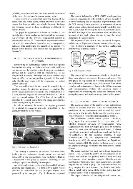
The segment <strong>of</strong> the map is used to control the speed,<br />
<strong>and</strong> the lateral displacement is used to control the steering.<br />
Fig. 2 shows a diagram <strong>of</strong> the control architecture<br />
implemented in the test vehicle.<br />
II. AUTONOMOUS VEHICLE. EXPERIMENTAL<br />
PLATFORM<br />
Researching in autonomous vehicles field has special<br />
interest because they can help to reduce traffic accidents<br />
<strong>and</strong> to improve the com<strong>for</strong>t in the driving. A com<strong>for</strong>table<br />
driving can be achieved with an efficient use <strong>of</strong> the<br />
longitudinal actuators. Although the lateral actions may<br />
have an effect on the longitudinal dynamic, in this work<br />
only throttle <strong>and</strong> brake will be considered as output<br />
control variables.<br />
The test vehicle used in this work is propelled by a<br />
gasoline motor. Its steering assistance is electric. The<br />
throttle pedal generates two signals: one <strong>of</strong> them from 0 to<br />
5 volts, <strong>and</strong> the range <strong>of</strong> the other one is half <strong>of</strong> it. That is<br />
used as control action. The CAN bus <strong>of</strong> the vehicle<br />
provides the control signal <strong>for</strong>m the speed <strong>and</strong> steering<br />
wheel angle given by the sensors.<br />
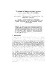
In order to automate the throttle, two signals generated<br />
by a digital to analogue converter embedded in the<br />
computer feed the motor control.<br />
Fig. 1. Test vehicle <strong>and</strong> the actuators<br />
The steering is controlled as follows. The wires lines<br />
leading to the assistance electric motor are cut <strong>and</strong><br />
replaced by a line taken directly from the battery. That is,<br />
a modulated width pulse is codified according to the<br />
analogue signal controlled by the computer.<br />
An additional braking system has been added without<br />
disabling the original one. It is <strong>for</strong>med by a pump whose<br />
pressure is controlled by an analogue signal, also<br />
generated by the computer. Fig. 1 shows the actuated<br />
Fig. 2. Vehicle control scheme.<br />
The control <strong>of</strong> the autonomous vehicle is divided into<br />
three main phases: perception, decision, <strong>and</strong> action. The<br />
first phase is responsible <strong>of</strong> receiving in<strong>for</strong>mation from<br />
the environment (position, speed, in<strong>for</strong>mation from others<br />
vehicles <strong>and</strong> infrastructure), through the different sensors<br />
<strong>and</strong> communication system. The decision phase is<br />
responsible <strong>for</strong> evaluating the conditions obtained in the<br />
perception phase, <strong>and</strong> sends the target to the action phase.<br />
III. FUZZY LOGIC LONGITUDINAL CONTROL<br />
The decision phase <strong>of</strong> the control <strong>of</strong> our autonomous<br />
vehicle is divided into two tasks: to determinate the<br />
conditions <strong>of</strong> the environment <strong>and</strong> to send the control<br />
references to the throttle, brake <strong>and</strong> the steering wheel.<br />
This work is only focused on the longitudinal control.<br />
The autonomous vehicle control system is based on<br />
fuzzy logic. An experimental fuzzy coprocessor called<br />
ORBEX (Spanish acronym <strong>of</strong> Experimental <strong>Fuzzy</strong><br />
Coprocessor) has been developed [14]. It is an inference<br />
motor that uses natural-language-based inputs. It allows<br />
variables to be defined <strong>and</strong> combined in rules <strong>of</strong> the <strong>for</strong>m:<br />
“IF…THEN...”. In the inference method, it uses<br />
Mamdani-type [16], <strong>and</strong> singleton-type membership<br />
functions to codify the output variables, as Tagaki <strong>and</strong><br />
Sugeno suggested [6]. The goal <strong>of</strong> the fuzzy logic is to use<br />
the expert knowledge to emulate the behaviour <strong>of</strong> human<br />
drivers.<br />
The starting point <strong>of</strong> this work can be found in previous<br />
works [15][17], where the control <strong>of</strong> both actuators on an<br />
electric van <strong>and</strong> on the gasoline vehicle used here was<br />
implemented with promising results. Details on the<br />
membership functions, rule base description, singleton<br />
outputs can be found in [17]. This controller defines two<br />
fuzzy outputs <strong>for</strong> each actuator, the throttle <strong>and</strong> brake.<br />
Also, a switch in the output <strong>of</strong> the control makes that both<br />
actuators cannot work at the same time.<br />
The input variables <strong>of</strong> the longitudinal control are: