Design and Implementation of a Neuro-Fuzzy System for ...
Design and Implementation of a Neuro-Fuzzy System for ...
Design and Implementation of a Neuro-Fuzzy System for ...

Create successful ePaper yourself
Turn your PDF publications into a flip-book with our unique Google optimized e-Paper software.
The values <strong>of</strong> the singleton outputs are listed in Table<br />
II:<br />
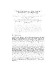
Fig. 5. Experiments by expert drivers.<br />
The parameters chosen <strong>for</strong> training the ANFIS system<br />
<strong>and</strong> its structure are as follows (Table I):<br />
TABLE I: ANFIS SYSTEM CONFIGURATION<br />
Algorithm<br />
<strong>System</strong><br />
Membership<br />
functions type<br />
Number <strong>of</strong><br />
membership<br />
functions<br />
Inference system<br />
ANFIS<br />
Twoinputs/singleoutput<br />
Trapezoidal<br />
3<br />
Takagi-Sugeno<br />
(constant)<br />
Number <strong>of</strong> rules 9<br />
Iterations 500<br />
Learning rate 0.001<br />
Training algorithm<br />
Training data set<br />
Validation data set<br />
Back<br />
propagation<br />
510 samples<br />
(1 experiment)<br />
987 samples<br />
(2 experiments)<br />
TABLE II: OUTPUT VALUES OF THE NEURO-FUZZY RULES<br />
a01 0.005979<br />
a02 0.08839<br />
a03 0.1901<br />
a04 0.01084<br />
a05 0.2245<br />
a06 -0.101<br />
a07 -0.02014<br />
a08 0.09938<br />
a09 -0.2186<br />
V. REAL TIME EXPERIMENTS AND RESULTS<br />
The real time experiments show the behaviour <strong>of</strong> the<br />
proposed neuro-fuzzy controller working in the<br />
autonomous vehicle. They were carried out in the same<br />
condition <strong>of</strong> the experiments <strong>of</strong> Section III (with a fuzzy<br />
controller) <strong>and</strong> IV (expert drivers). That is, vehicle speeds<br />
between 10 km/h <strong>and</strong> 20 km/h <strong>and</strong> the same track.<br />
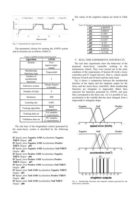
Fig. 6 shows a comparison between the membership<br />
function <strong>of</strong> the inputs <strong>and</strong> the singleton output <strong>for</strong> the<br />
fuzzy <strong>and</strong> the neuro-fuzzy controllers. Both membership<br />
functions are triangular or trapezoidal. Black lines<br />
represent the functions generated by ANFIS, <strong>and</strong> gray<br />
lines correspond to the fuzzy one. As it is possible to see,<br />
acceleration is the variable that has most changed, from a<br />
trapezoidal to triangular shape.<br />
The rule base <strong>of</strong> the longitudinal control generated by<br />
the neuro-fuzzy system is described by the following<br />
rules:<br />
IF Speed_error Negative AND Acceleration Negative<br />
THEN Output a05<br />
IF Speed_error Negative AND Acceleration Positive<br />
THEN Output a02<br />
IF Speed_error Negative AND Acceleration Null THEN<br />
Output a03<br />
IF Speed_error Positive AND Acceleration Negative<br />
THEN Output a06<br />
IF Speed_error Positive AND Acceleration Positive<br />
THEN Output a07<br />
IF Speed_error Positive AND Acceleration Null THEN<br />
Output a09<br />
IF Speed_error Null AND Acceleration Negative THEN<br />
Output a01<br />
IF Speed_error Null AND Acceleration Positive THEN<br />
Output a04<br />
IF Speed_error Null AND Acceleration Null THEN<br />
Output a08<br />
Fig. 6. Membership functions <strong>and</strong> singleton outputs generated by the<br />
neuro-fuzzy controller.