Full paper Minimizing Energy Consumption in Hexapod Robots
Full paper Minimizing Energy Consumption in Hexapod Robots
Full paper Minimizing Energy Consumption in Hexapod Robots

Create successful ePaper yourself
Turn your PDF publications into a flip-book with our unique Google optimized e-Paper software.
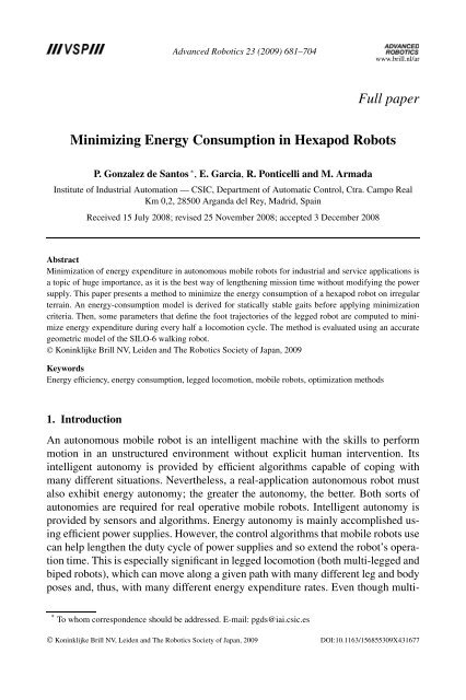
Advanced Robotics 23 (2009) 681–704www.brill.nl/ar<strong>Full</strong> <strong>paper</strong><strong>M<strong>in</strong>imiz<strong>in</strong>g</strong> <strong>Energy</strong> <strong>Consumption</strong> <strong>in</strong> <strong>Hexapod</strong> <strong>Robots</strong>P. Gonzalez de Santos ∗ , E. Garcia, R. Ponticelli and M. ArmadaInstitute of Industrial Automation — CSIC, Department of Automatic Control, Ctra. Campo RealKm 0,2, 28500 Arganda del Rey, Madrid, Spa<strong>in</strong>Received 15 July 2008; revised 25 November 2008; accepted 3 December 2008AbstractM<strong>in</strong>imization of energy expenditure <strong>in</strong> autonomous mobile robots for <strong>in</strong>dustrial and service applications isa topic of huge importance, as it is the best way of lengthen<strong>in</strong>g mission time without modify<strong>in</strong>g the powersupply. This <strong>paper</strong> presents a method to m<strong>in</strong>imize the energy consumption of a hexapod robot on irregularterra<strong>in</strong>. An energy-consumption model is derived for statically stable gaits before apply<strong>in</strong>g m<strong>in</strong>imizationcriteria. Then, some parameters that def<strong>in</strong>e the foot trajectories of the legged robot are computed to m<strong>in</strong>imizeenergy expenditure dur<strong>in</strong>g every half a locomotion cycle. The method is evaluated us<strong>in</strong>g an accurategeometric model of the SILO-6 walk<strong>in</strong>g robot.© Kon<strong>in</strong>klijke Brill NV, Leiden and The Robotics Society of Japan, 2009Keywords<strong>Energy</strong> efficiency, energy consumption, legged locomotion, mobile robots, optimization methods1. IntroductionAn autonomous mobile robot is an <strong>in</strong>telligent mach<strong>in</strong>e with the skills to performmotion <strong>in</strong> an unstructured environment without explicit human <strong>in</strong>tervention. Its<strong>in</strong>telligent autonomy is provided by efficient algorithms capable of cop<strong>in</strong>g withmany different situations. Nevertheless, a real-application autonomous robot mustalso exhibit energy autonomy; the greater the autonomy, the better. Both sorts ofautonomies are required for real operative mobile robots. Intelligent autonomy isprovided by sensors and algorithms. <strong>Energy</strong> autonomy is ma<strong>in</strong>ly accomplished us<strong>in</strong>gefficient power supplies. However, the control algorithms that mobile robots usecan help lengthen the duty cycle of power supplies and so extend the robot’s operationtime. This is especially significant <strong>in</strong> legged locomotion (both multi-legged andbiped robots), which can move along a given path with many different leg and bodyposes and, thus, with many different energy expenditure rates. Even though multi-* To whom correspondence should be addressed. E-mail: pgds@iai.csic.es© Kon<strong>in</strong>klijke Brill NV, Leiden and The Robotics Society of Japan, 2009 DOI:10.1163/156855309X431677
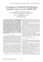
P. Gonzalez de Santos et al. / Advanced Robotics 23 (2009) 681–704 683Figure 1. SILO-6 walk<strong>in</strong>g robot.Thus, we can see the importance elevation maps have held for autonomous mobilerobots on irregular terra<strong>in</strong> for about the last decade. Elevation maps have beenused ma<strong>in</strong>ly for navigation purposes <strong>in</strong> general, and, <strong>in</strong> some legged-robot applications,elevation maps have also provided a start<strong>in</strong>g po<strong>in</strong>t for f<strong>in</strong>d<strong>in</strong>g adequatefootholds to improve traction and reduce foot slippage. However, terra<strong>in</strong> <strong>in</strong>formationcan also help reduce the support torques of legged robots and, thus, reduce theenergy required.This <strong>paper</strong> focuses on the m<strong>in</strong>imization of energy expenditure <strong>in</strong> hexapod robotswalk<strong>in</strong>g on irregular terra<strong>in</strong> based on aprioriknowledge of the terra<strong>in</strong> <strong>in</strong> front ofthe robot. This work is motivated by a real need to <strong>in</strong>crease the energy autonomyof the SILO-6 walk<strong>in</strong>g robot. The SILO-6 is a six-legged robot developed as a mobileplatform for the DYLEMA project [15, 16], whose ma<strong>in</strong> aim is to develop alocomotion system to <strong>in</strong>tegrate relevant technologies <strong>in</strong> the fields of legged robotsand sensors to address needs <strong>in</strong> humanitarian dem<strong>in</strong><strong>in</strong>g activities. The hexapod isendowed with a 5-d.o.f. manipulator <strong>in</strong> front, which handles a sensor head to scanthe terra<strong>in</strong> <strong>in</strong> the front of the hexapod cover<strong>in</strong>g its whole sprawl (see Fig. 1). Thisscann<strong>in</strong>g manipulator is fast enough to scan the terra<strong>in</strong> without jeopardiz<strong>in</strong>g thehexapod speed. The sensor head consists of a m<strong>in</strong>e-detect<strong>in</strong>g set and a network of<strong>in</strong>frared (IR) sensors. The detect<strong>in</strong>g set is a commercial device capable of detect<strong>in</strong>gvery small metallic components. The IR sensors are used to ma<strong>in</strong>ta<strong>in</strong> the sensorhead at a given height above the terra<strong>in</strong> and roughly parallel to any terra<strong>in</strong> irregularities.Thus, this sensor head can be used to generate an elevation map of whatlies <strong>in</strong> front of the robot, which can <strong>in</strong> turn be used to m<strong>in</strong>imize the energy requiredto move the robot. Figure 2 shows an example of reconstruction of an irregular terra<strong>in</strong>composed of different geometric objects us<strong>in</strong>g the described sensor head and a
P. Gonzalez de Santos et al. / Advanced Robotics 23 (2009) 681–704 689These foot forces depend on the foot positions that determ<strong>in</strong>e matrices R i ,i ∈[p,q,r], andR R , and <strong>in</strong> this case they are def<strong>in</strong>ed by the alternat<strong>in</strong>g-tripod gait(see Refs [21, 23] for foothold computation). Note that the wrench W pqr <strong>in</strong> (21)conta<strong>in</strong>s the <strong>in</strong>ertial forces and moments, and the external forces as well. Inertialforces and moments are caused by the motion of the masses of the leg l<strong>in</strong>ks. Theseterms are obta<strong>in</strong>ed by comput<strong>in</strong>g first the accelerations of the COG of all of thel<strong>in</strong>ks, COG L , along a semi-cycle. These accelerations are determ<strong>in</strong>ed by the accelerationsof the feet that will be def<strong>in</strong>ed below. The only external force act<strong>in</strong>g <strong>in</strong> therobot is the weight, W , tak<strong>in</strong>g <strong>in</strong>to consideration the condition C-2.The solution of (21) along with (10) provides the jo<strong>in</strong>t torques. The speed <strong>in</strong>every jo<strong>in</strong>t is given by:ω ∗ i = J−1 iv i , (22)where ω ∗ i and v i are given by:ω ∗ i = (ω∗ i1ωi2 ∗ ωi3 ∗ )T = ( ˙θi1∗ ˙θi2∗ ˙θi3 ∗ )T (23)v i = ( ẋ i ẏ i ż i ) T .θ ij is the position of jo<strong>in</strong>t j of leg i and (x i y i z i ) T is the position of foot i.Aga<strong>in</strong>, ωij ∗ represents the speed <strong>in</strong> jo<strong>in</strong>t j of leg i, while ω ij represents the speed <strong>in</strong>motor j of leg i.The speed and torques <strong>in</strong> jo<strong>in</strong>t j and motor j of leg i are related through thejo<strong>in</strong>t-gear ratio, N j , and the jo<strong>in</strong>t gear’s mechanical efficiency, η j , by:ωij ∗ = ω ijN j(24)τij ∗ = η j N j τ ij .Therefore, (8) can be re-written as:∫ T 6∑ 3∑( ( ω∗ij(t)τij ∗E =(t) ))R j+0η j k 2 i=1 j=1M jηj 2N j2 (τij ∗ )2 (t) dt. (25)Thus, the algorithm to compute the energy consumed <strong>in</strong> a hexapod consists of:Step 1. Set the body velocity, body height, leg stroke R x and foot trajectories.Step 2. Compute foot positions (x i (k)y i (k)z i (k)) T for <strong>in</strong>stant k us<strong>in</strong>g thealternat<strong>in</strong>g-tripod gait [21, 23].Step 3. Compute the trajectory, speed and acceleration of every COG L .Step 4. With both the COG L accelerations and l<strong>in</strong>k masses compute the <strong>in</strong>ertialforces and moments.Step 5. Compute foot forces f i by solv<strong>in</strong>g the force-distribution problem with (21).Step 6. Compute torques τij ∗ us<strong>in</strong>g (10).
690 P. Gonzalez de Santos et al. / Advanced Robotics 23 (2009) 681–704Step 7. Compute jo<strong>in</strong>t speed ωi ∗ with (22).Step 8. Compute the total energy dur<strong>in</strong>g half a locomotion cycle with (25), whereT = T cycle /2.4.2. K<strong>in</strong>ematic Model of the <strong>Hexapod</strong>Section 1 mentioned that the ma<strong>in</strong> aim of this work is to configure an energyefficientwalk<strong>in</strong>g robot for humanitarian dem<strong>in</strong><strong>in</strong>g activities. This robot model isconsidered here<strong>in</strong> for simulation purposes. The mechanical and geometric parametersof SILO-6 [15, 16] are def<strong>in</strong>ed <strong>in</strong> Fig. 4 and summarized <strong>in</strong> Table 1. With thoseparameters, a wire model of the robot can be obta<strong>in</strong>ed as illustrated <strong>in</strong> Fig. 5. Theasterisk represents the location of the COG L of each l<strong>in</strong>k. The COG of the body,COG B , is assumed to be at the geometric center of the body. With this model, wecompute the position of the overall COG of the robot, COG R , as well as the forcesand moments act<strong>in</strong>g on it, which depend on the motion of the feet.The foot positions have been designed to m<strong>in</strong>imize the accelerations and, thus,to reduce the dynamic effects. The foot trajectory for each foot <strong>in</strong> an external referenceframe will consists of a straight trajectory for the foot <strong>in</strong> its support phase anda transfer trajectory composed of three subtrajectories: a circular trajectory to risethe foot, a straight trajectory to move the foot forward and a circular trajectory toTable 1.Ma<strong>in</strong> SILO-6 featuresBodydimensions (m)length L B 0.88front/rear width D 0.38middle width 0.63height 0.26stroke pitch P x 0.365mass (kg) 28.2speed (m/s) 0.05Legl<strong>in</strong>klength(m)a 1 0.084a 2 0.250a 3 0.250stroke (R x ) (m) 0.25mass (kg) 4.3foot speed (m/s)transfer phase 0.140support phase 0.05Robottotal mass (kg) 54See Fig. 4 for parameter def<strong>in</strong>itions.
P. Gonzalez de Santos et al. / Advanced Robotics 23 (2009) 681–704 691Figure 5. Wire model of the hexapod. Foot positions are <strong>in</strong>dicated <strong>in</strong> dark circles. The COG of everyl<strong>in</strong>k is <strong>in</strong>dicated with an asterisk.place the foot on the ground (Fig. 6b). With these trajectories, we guarantee that footaccelerations at foot takeoff and land<strong>in</strong>g are m<strong>in</strong>imized. Figure 6 plots the foot trajectory<strong>in</strong> both the body reference frame (Fig. 6a) and the external reference frame(Fig. 6b). Note that the foot trajectory <strong>in</strong> the body reference frame is transformedto jo<strong>in</strong>t trajectories by us<strong>in</strong>g the leg k<strong>in</strong>ematic model described <strong>in</strong> the Appendix.Apply<strong>in</strong>g these jo<strong>in</strong>t trajectories <strong>in</strong>to the hexapod’s controller (see a superpositionof robot poses <strong>in</strong> Fig. 7), the <strong>in</strong>ertial forces and moments act<strong>in</strong>g <strong>in</strong> the COG R arecomputed.It is worth clarify<strong>in</strong>g that of the energy expended <strong>in</strong> the walk<strong>in</strong>g mechanism(stand, traction, leg sw<strong>in</strong>g and head loss), the contribution of the leg sw<strong>in</strong>g is <strong>in</strong>significant.Every leg <strong>in</strong> its stand phase must support about one-third of the robot’sweight, while a leg <strong>in</strong> the sw<strong>in</strong>g phase does not support any load. That means thelegs <strong>in</strong> the sw<strong>in</strong>g phase do not expend energy <strong>in</strong> comparison to the legs <strong>in</strong> the standphase. Moreover, all the legs <strong>in</strong> the sw<strong>in</strong>g phase expend quite the same energy;therefore, the difference between two foothold solutions is basically the differencebetween their support phases. From the theoretical standpo<strong>in</strong>t, there is, of course,a slight difference <strong>in</strong> the energy consumed for plac<strong>in</strong>g a foot <strong>in</strong> different po<strong>in</strong>ts atthe end of the sw<strong>in</strong>g phase, but they are quite close to each other and a sw<strong>in</strong>g phaseis an unload motion, so this energy can be neglected. Additionally, the algorithmrelies on an optimization method and the model must be kept significant enough,but yet small to be computationally efficient. This is the reason that <strong>in</strong> our modelwe discard the energy consumed <strong>in</strong> the sw<strong>in</strong>g legs.
692 P. Gonzalez de Santos et al. / Advanced Robotics 23 (2009) 681–704(a)(b)Figure 6. Foot trajectories seen by an observer at (a) the body reference frame (trajectory <strong>in</strong> supportfrom A to B) and (b) the external reference frame (C and D are the support po<strong>in</strong>ts).Figure 7. Superposition of robot poses show<strong>in</strong>g the foot and COG L trajectories.
4.3. Simulation ResultsP. Gonzalez de Santos et al. / Advanced Robotics 23 (2009) 681–704 693Let us compute the energy expended by the SILO-6 model when the robot walksalong a straight, horizontal l<strong>in</strong>e with its body leveled and perform<strong>in</strong>g the foot trajectoryplotted <strong>in</strong> Fig. 6 (see also Fig. 7). The body speed is assumed to be 0.1 m/s,which means the feet <strong>in</strong> support move at 0.1 m/s; however, the feet <strong>in</strong> the transferphase reach up to 0.55 m/s; the leg stroke of the gait, R x ,is0.25mandthedistance from every foot trajectory to the z-axis of its leg reference frame, L i ,is0.25 m for feet <strong>in</strong> the support phase (tripod i ∈[1, 4, 5] <strong>in</strong> the half locomotion cycleunder study). With these premises and the mechanical, geometric and electrical parametersprovided <strong>in</strong> Tables 1 and 2, we obta<strong>in</strong> the motor torques and motor speeddur<strong>in</strong>g half a locomotion cycle plotted <strong>in</strong> Fig. 8. These magnitudes are the base toobta<strong>in</strong> the power. For the sake of brevity, only the torques and speed for leg 1 areillustrated. Note that for an ideal mass-less leg robot the torque <strong>in</strong> motor 1 shouldTable 2.SILO-6 jo<strong>in</strong>t parametersLeg jo<strong>in</strong>t Motor GearTorque constant Resistance Rate EfficiencyK M (Nm/A) R () N η (%)1 0.0333 0.62 246 632 0.0333 0.62 881.5 423 0.0333 0.62 881.5 42Figure 8. Torques and speed <strong>in</strong> motors of leg 1 dur<strong>in</strong>g half a locomotion cycle.
694 P. Gonzalez de Santos et al. / Advanced Robotics 23 (2009) 681–704Figure 9. Mechanical power <strong>in</strong> motors.be null, because motor 1 does not contribute to robot support or motion at constantspeed; however, Fig. 8 shows that <strong>in</strong> that jo<strong>in</strong>t the torque is not completely null becauseof the effect of the COG L of the l<strong>in</strong>ks. Note that <strong>in</strong> this case the robot is onflat, horizontal terra<strong>in</strong>.Figure 9 plots the mechanical power consumption, along half a locomotion cycle,while legs 1, 4 and 5 are <strong>in</strong> support. Figure 10 plots the heat loss for the samelegs and same conditions. These power contributions have been plotted <strong>in</strong>dividuallyfor the sake of comparison. We can observe that heat loss is greater than mechanicalpower and the area under the heat loss (energy) is also greater than the areaunder the mechanical power. This fact highlights the importance of heat loss overmechanical power — a term that has been neglected <strong>in</strong> many studies. For <strong>in</strong>stance,the pioneer<strong>in</strong>g work of Lapsh<strong>in</strong> [2] considers only the energy consumption on themach<strong>in</strong>e weight, the energy consumption on the traction generation and the energyfor the leg sw<strong>in</strong>g phases. A more recent work [24] m<strong>in</strong>imizes the sum of the squareacceleration through the entire trajectory. However, by add<strong>in</strong>g the two power contributionsand <strong>in</strong>tegrat<strong>in</strong>g this function over half a locomotion cycle, we f<strong>in</strong>d thatthe mechanical energy required to support and move our hexapod is E M = 17.22 J,
P. Gonzalez de Santos et al. / Advanced Robotics 23 (2009) 681–704 695Figure 10. Heat loss <strong>in</strong> motors.while the energy due to heat loss is E H = 37.01 J. That makes a total energy ofE T = 54.23 J for a tripod (half a locomotion cycle), which means that the heat lossis about 68.24% of the total energy.5. M<strong>in</strong>imization of <strong>Energy</strong> <strong>Consumption</strong><strong>Energy</strong> consumption depends on motor torque and motor speed, and these parametersdepend on foot positions, as mentioned above. Therefore, vary<strong>in</strong>g the foottrajectories is one way of chang<strong>in</strong>g the energy required to support and propel arobot.In our approach, the leg stroke, R x , and leg phases (i.e., the leg-lift<strong>in</strong>g <strong>in</strong>stants<strong>in</strong> a locomotion cycle) rema<strong>in</strong> constant. The period of the locomotion cycle willdepend on the body speed. Foot trajectories <strong>in</strong> support are straight segments of afixed length (R x ); thus, the only parameter for def<strong>in</strong><strong>in</strong>g different foot trajectoriesis the distance from the foot trajectory to the z-axis of the leg reference frame, L i ,and the foot trajectory height, H i (see Fig. 4). Note that the robot is regarded asmov<strong>in</strong>g <strong>in</strong> a horizontal straight l<strong>in</strong>e with respect to a fixed external reference frame.
P. Gonzalez de Santos et al. / Advanced Robotics 23 (2009) 681–704 697constra<strong>in</strong>ed, nonl<strong>in</strong>ear m<strong>in</strong>imization method also known as the flexible polyhedronmethod [25]. This method requires a start<strong>in</strong>g po<strong>in</strong>t (L p0 ,L q0 ,L r0 ) and f<strong>in</strong>ds a localm<strong>in</strong>imum (L ∗ p ,L∗ q ,L∗ r ) of the function E:m<strong>in</strong>imize Lp ,L q ,L r{E(L p ,L q ,L r )}→(L ∗ p ,L∗ q ,L∗ r ). (28)Equation (25) is a unimodal function for the range of <strong>in</strong>put values L i ∈[−0.1 m, −0.35 m] as numerically shown below (Fig. 11); therefore, the m<strong>in</strong>imumfound by (28) can be considered a global m<strong>in</strong>imum. Note that the <strong>in</strong>itial values ofL i are chosen to be <strong>in</strong>side the leg workspace so that the probability of f<strong>in</strong>d<strong>in</strong>g asolution out of the leg workspace is negligible. However, if the <strong>in</strong>verse-k<strong>in</strong>ematicfunction of the leg f<strong>in</strong>ds a po<strong>in</strong>t out of the workspace, it is not considered and therobot will perform the next step under non-optimal conditions.5.2. Comput<strong>in</strong>g ResultsTo illustrate the algorithm results, let us consider that SILO-6 is walk<strong>in</strong>g on flatterra<strong>in</strong> at a height of H =−0.15 m, and apply (28) to compute the values of L p ,L q and L r that m<strong>in</strong>imize the energy. For the SILO-6 parameters summarized <strong>in</strong>Tables 1 and 2, and start<strong>in</strong>g at the <strong>in</strong>itial solution L p0 = L q0 = L r0 = 0.25 m,the optimal solution is L p = 0.255 m, L q = 0.254 m and L r = 0.255 m, and them<strong>in</strong>imum energy is 49.63 J.Let us now assume that the robot is walk<strong>in</strong>g on an irregular terra<strong>in</strong> that consistsof a horizontal base plane with several protrusions, P , such that the first tripod hasfootholds on the protrusions at H i =−0.15 m and the second tripod has footholdson the base plane at H i =−0.30 m (Fig. 12). If the robot walks dur<strong>in</strong>g the first semicyclewith foot trajectories at L p = 0.255 m, L q = 0.254 m and L r = 0.255 m, therobot consumes the m<strong>in</strong>imum energy as shown above. However, if the robot keepsthe same foot-trajectory parameters for the second tripod, the energy expenditureis 52.04 J, whereas reapplication of the m<strong>in</strong>imization algorithm at this po<strong>in</strong>t wouldreduce the energy to 50.42 J for L p = 0.210 m, L q = 0.224 m and L r = 0.210 m.Note that the sav<strong>in</strong>gs of 1.62 J is for a body motion of about R x = 0.25 m at a bodyFigure 12. Sketch of the hexapod over irregular terra<strong>in</strong>.
698 P. Gonzalez de Santos et al. / Advanced Robotics 23 (2009) 681–704Table 3.<strong>Energy</strong> expenditure for different foot positionsH i (m)−0.10 −0.15 −0.20 −0.25 −0.30 −0.35L ∗ 1 (m) 0.248 0.255 0.250 0.235 0.210 0.074L ∗ 4 (m) 0.244 0.254 0.252 0.242 0.224 0.197L ∗ 5 (m) 0.248 0.255 0.250 0.235 0.210 0.074<strong>Energy</strong> (J)H i ′ −0.10 39.66 39.88 39.76 39.94 42.83 74.60−0.15 49.82 49.63 49.66 50.35 53.46 70.60−0.20 54.27 54.23 54.21 54.54 56.50 64.95−0.25 54.36 54.65 54.49 54.23 54.88 58.13−0.30 51.40 52.04 51.75 50.91 50.42 50.42−0.35 46.19 47.12 46.73 45.42 44.04 41.60speed of 0.1 m/s. These values are shown <strong>in</strong> Table 3, which <strong>in</strong>cludes the energyexpenditure under different body height, H i , and leg spread, L i .InTable3,L ∗ iisthe foot position that m<strong>in</strong>imizes the energy (<strong>in</strong> bold) for a given H i . H ′i representsthe height of the body at the computation of the energy. The rows <strong>in</strong> the energypart of Table 3 conta<strong>in</strong> the energy expenditure for a given body height, Hi ′,whenthe foot positions are those <strong>in</strong>dicated <strong>in</strong> the same column. Thus, the m<strong>in</strong>imum <strong>in</strong>every row appears at the cell H i = Hi ′ (<strong>in</strong>dicated <strong>in</strong> bold). Note that for both supporttripods the body is on the same horizontal plane; therefore, there is not any energyexpended for mov<strong>in</strong>g up or down the robot’s body.Figure 13 illustrates the energy surface as a function of H i and Hi ′ . The po<strong>in</strong>ts ofm<strong>in</strong>imum energy for a given Hi ′ are <strong>in</strong>dicated with an asterisk. The surface showshow the m<strong>in</strong>imum energy expenditure is obta<strong>in</strong>ed for low or high body heights,which correspond with the <strong>in</strong>sect or mammal robot configuration. However, for agiven body height, Hi ′ , the m<strong>in</strong>imum energy is obta<strong>in</strong>ed at a specific foot positions,L i .Similar examples can be run consider<strong>in</strong>g other type of irregular terra<strong>in</strong>. For <strong>in</strong>stance,the first tripod could be at the base plane with H i =−0.15 m and the secondtripod could be <strong>in</strong>side holes such as H i =−0.30 m. The results <strong>in</strong> both examples arethe same. A general irregular terra<strong>in</strong> with the footholds at different heights can alsobe used, but we prefer to present a simple irregular terra<strong>in</strong> for the sake of clarity.6. Practical Implementation IssuesThe earlier sections have presented the theory for m<strong>in</strong>imiz<strong>in</strong>g the energy consumption<strong>in</strong> a hexapod robot when it performs a tripod gait along a straight l<strong>in</strong>e.
P. Gonzalez de Santos et al. / Advanced Robotics 23 (2009) 681–704 699Figure 13. <strong>Energy</strong> expenditure for different body heights.A numerical example of the procedure has illustrated that it is possible to saveabout 3.21% of the energy for a hypothetical, special case where every foot <strong>in</strong> atripod is at the same height. In such a case, a lookup table with the solution to theproblem could be an adequate practical solution to avoid comput<strong>in</strong>g the optimizationprocedure <strong>in</strong> real-time.In a practical case, when the robot is walk<strong>in</strong>g on irregular terra<strong>in</strong> every footwill normally be placed at a different height <strong>in</strong> a range from −0.10 m up to about−0.35 m. The lookup table solution seems to be unpractical, even if we use a reasonablediscretization of the foot heights, and the implementation <strong>in</strong> real-time ofthe m<strong>in</strong>imization algorithm is the only sensible solution, which br<strong>in</strong>gs about furthertechnical comput<strong>in</strong>g problems.Let us assume that we know, as <strong>in</strong> our real application <strong>in</strong>troduced <strong>in</strong> Section 1,an elevation map of the terra<strong>in</strong> where the robot is stepp<strong>in</strong>g on. That means we knowthe z-foothold component as a function of the x and y foothold components. Thus,we can compute the m<strong>in</strong>imization algorithm at the beg<strong>in</strong>n<strong>in</strong>g of the transfer phase,which lasts for about t T = 2.5 s, tak<strong>in</strong>g <strong>in</strong>to consideration the average speed ofthe transfer phase v T = 0.1 m/s and the leg stroke R x = 0.25 m. This time t T is<strong>in</strong>sufficient for runn<strong>in</strong>g the m<strong>in</strong>imization algorithm <strong>in</strong> the PC-bus based computer(<strong>in</strong>dustrial ISA PC Pentium II 667 MHz) on board SILO-6. Additional comput<strong>in</strong>gresources must be provided on the prototype to implement the method presented<strong>in</strong> this <strong>paper</strong>. This is part of the technical work envisaged for the next step of the
700 P. Gonzalez de Santos et al. / Advanced Robotics 23 (2009) 681–704project. Nevertheless, the most important result is to quantify the range of energyconsumption we can save by apply<strong>in</strong>g m<strong>in</strong>imization methods.7. Conclusions<strong>Energy</strong> optimization is an important topic for autonomous robots, because it is theway of <strong>in</strong>creas<strong>in</strong>g duty time for missions without modify<strong>in</strong>g the power supply onboard the robot.This <strong>paper</strong> studies the energy required for six-legged robots us<strong>in</strong>g alternat<strong>in</strong>gtripodgaits, the fastest gait for hexapods, and derives a method to m<strong>in</strong>imize theenergy for one tripod. M<strong>in</strong>imization of consecutive tripods m<strong>in</strong>imizes the energythroughout an entire trajectory. The method works on any k<strong>in</strong>d of irregular terra<strong>in</strong>,although some simple models for irregular terra<strong>in</strong> have been used <strong>in</strong> the examplespresented above.The method requires some advance knowledge of the terra<strong>in</strong>; therefore, it isapplicable to robots capable of obta<strong>in</strong><strong>in</strong>g an elevation map of the terra<strong>in</strong>. <strong>Energy</strong>expenditure was computed by us<strong>in</strong>g the SILO-6 walk<strong>in</strong>g robot as a model. This robotis designed for humanitarian dem<strong>in</strong><strong>in</strong>g missions and uses a system to obta<strong>in</strong> anelevation map of the terra<strong>in</strong> <strong>in</strong> front of the robot.This <strong>paper</strong> provides some figures for the energy saved <strong>in</strong> such a robot and researchis ongo<strong>in</strong>g on the computation of the method for real-time applications.<strong>Energy</strong> consumed by electronics (computers, drivers, analog I/O, etc.) constitutes alarge source of energy loss. Dim<strong>in</strong>ish<strong>in</strong>g this energy loss is a technical concern thatmust always be taken <strong>in</strong>to account.AcknowledgementsThis work was supported by the Spanish M<strong>in</strong>istry of Education and Science throughCICYT grant DPI2004-05824.References1. Q. Huang, T. Hase and K. Ono, Optimal trajectory plann<strong>in</strong>g method us<strong>in</strong>g <strong>in</strong>equality state constra<strong>in</strong>tfor biped walk<strong>in</strong>g robot with upper body mass, Special Issue on New Trends of Motion andVibration Control, J. Syst. Des. Dyn. (JSME Dyn. Meas. Control Div.) 1, 168–179 (2007).2. V. V. Lapsh<strong>in</strong>, <strong>Energy</strong> consumption of a walk<strong>in</strong>g mach<strong>in</strong>e. Model estimations and optimization,<strong>in</strong>: Proc. 7th Conf. on Advanced Robotics, San Feliu de Guixols, pp. 420–425 (1995).3. D. E. Or<strong>in</strong> and S. Y. Oh, Control of force distribution <strong>in</strong> robotic mechanisms conta<strong>in</strong><strong>in</strong>g closek<strong>in</strong>ematic cha<strong>in</strong>s, J. Dyn. Syst. Meas. Control 103, 134–141 (1981).4. M. A. Nahon and J. Angeles, M<strong>in</strong>imization of power losses <strong>in</strong> cooperat<strong>in</strong>g manipulators, J. Dyn.Syst. Meas. Control 114, 213–219 (1992).5. D. W. Marhefka, Gait plann<strong>in</strong>g for power m<strong>in</strong>imization <strong>in</strong> walk<strong>in</strong>g mach<strong>in</strong>es, Master’s Thesis,Ohio State University (1996).6. D. W. Marhefka and D. E. Or<strong>in</strong>, Gait plann<strong>in</strong>g for energy efficiency <strong>in</strong> walk<strong>in</strong>g mach<strong>in</strong>es, <strong>in</strong>: Proc.IEEE Int. Conf. on Robotics and Automation, Alburquerque, NM, pp. 474–480 (1997).
P. Gonzalez de Santos et al. / Advanced Robotics 23 (2009) 681–704 7017. M. F. Silva, J. A. Tenreiro Machado and A. M. Endes Lopes, <strong>Energy</strong> analysis of multi-leggedlocomotion systems, <strong>in</strong>: Proc. 4th Conf. on Climb<strong>in</strong>g and Walk<strong>in</strong>g <strong>Robots</strong>, Karlsruhe, pp. 143–150(2001).8. T. Zel<strong>in</strong>ska, Efficiency analysis <strong>in</strong> the design of walk<strong>in</strong>g mach<strong>in</strong>es, J. Theor. Appl. Mech. 38,693–708 (2000).9. V. V. Zhoga, Computation of walk<strong>in</strong>g robots movement energy expenditure, <strong>in</strong>: Proc. IEEE Int.Conf. on Robotics and Automation, Leuven, pp. 163–168 (1998).10. J. E. Bares and D. S. Wettergreen, Dante II: technical description, results and lesson learned, Int.J. Robotics Res. 18, 621–649 (1999).11. J. Bares and W. Whittaker, Configuration of autonomous walkers for extreme terra<strong>in</strong>, Int. J. RoboticsRes. 12, 535–559 (1993).12. Nomad: Lunar Rover Navigation, http://www.cs.cmu.edu/∼lri/nav97.html (1997).13. C. Ye and J. Borenste<strong>in</strong>, A new terra<strong>in</strong> mapp<strong>in</strong>g method for mobile robot obstacle negotiation, <strong>in</strong>:Proc. UGV Technology Conf. at the 2003 SPIE AeroSense Symp., San Jose, CA, pp. 2561–2562(2003).14. P. Pfaff and W. Burgard, An efficient extension of elevation maps for outdoor terra<strong>in</strong> mapp<strong>in</strong>g, <strong>in</strong>:Proc. 5th Int. Conf. on Field and Service Robotics, Port Douglas, QLD, pp. 165–176 (2005).15. P. Gonzalez de Santos, J. A. Cobano, E. Garcia, J. Estremera and M. A. Armada, A six-leggedrobot-based system for humanitarian dem<strong>in</strong><strong>in</strong>g missions, Mechatronics 17, 417–430 (2007).16. SILO-6 website, http://www.iai.csic.es/users/silo617. S. M. Song and K. J. Waldron, Mach<strong>in</strong>es that Walk: the Adaptive Suspension Vehicle. MIT Press,Cambridge, MA (1989).18. M. Kaneko, S. Tachi, K. Tanie and M. Abe, Basic study on similarity <strong>in</strong> walk<strong>in</strong>g mach<strong>in</strong>es from apo<strong>in</strong>t of energetic efficiency, IEEE J. Robotics Automat. 3, 19–30 (1987).19. J. Nishii, K. Ogawa and R. Suzuki, The optimal gait pattern <strong>in</strong> hexapods based on energetic efficiency,<strong>in</strong>: Proc. 3rd Int. Symp. on Artificial Life and Robotics, Beppu, Vol. 1, pp. 106–109 (1998).20. S. Ma, Time optimal control of manipulators with limit heat characteristics of actuator, Adv. Robotics16, 309–324 (2002).21. P. Gonzalez de Santos, E. Garcia and J. Estremera, Improv<strong>in</strong>g walk<strong>in</strong>g-robot performances byoptimiz<strong>in</strong>g leg distribution, Autonomous <strong>Robots</strong> 23, 247–258 (2007).22. W. Y. Jiang, A. M. Liu and D. Howard, Foot-force distribution <strong>in</strong> legged robots, <strong>in</strong>: Proc. 4th Int.Conf. on Climb<strong>in</strong>g and Walk<strong>in</strong>g <strong>Robots</strong>, Karlsruhe, pp. 331–338 (2001).23. P. Gonzalez de Santos, J. Estremera and E. Garcia, Optimiz<strong>in</strong>g leg distribution around the body <strong>in</strong>walk<strong>in</strong>g robots, <strong>in</strong>: Proc. IEEE Int. Conf. on Robotics and Automation, Barcelona, pp. 3218–3223(2005).24. R. Kurame, K. Yoneda and S. Hirose, Feedforward and feedback trot gait control for quadrupedwalk<strong>in</strong>g vehicle, Autonomous <strong>Robots</strong> 12, 157–172 (2002).25. J. C. Lagarias, J. A. Reeds, M. H. Wright and P. E. Wright, Convergence properties of the Nelder–Mead simplex method <strong>in</strong> low dimensions, SIAM J. Optimizat. 9, 112–147 (1998).AppendixThis Appendix presents the leg k<strong>in</strong>ematics used for simulation and control purposes(Fig. A.1). The direct k<strong>in</strong>ematic relationships consist <strong>in</strong> envision<strong>in</strong>g the position(x i ,y i ,z i ) T of foot i as a function of the jo<strong>in</strong>t components (θ i1 ,θ i2 ,θ i3 ) T :(x i ,y i ,z i ) T = T DIR (θ i1 ,θ i2 ,θ i3 ), (A.1)
702 P. Gonzalez de Santos et al. / Advanced Robotics 23 (2009) 681–704Figure A.1. SILO-6 prototype, dimensions and reference systems.where⎛⎞Cθ i1 (a 3 C(θ i2 + θ i3 ) + a 2 Cθ i2 + a 1 )T DIR = ⎝ Sθ i1 (a 3 C(θ i2 + θ i3 ) + a 2 Cθ i2 + a 1 ) ⎠ .a 3 S(θ i2 + θ i3 ) + a 2 Sθ i2Note that we simplify the notation by writ<strong>in</strong>g C for cos and S for s<strong>in</strong>.The <strong>in</strong>verse k<strong>in</strong>ematics is def<strong>in</strong>ed by:where:and:(A.2)(θ i1 θ i2 θ i3 ) T = T INV (x i ,y i ,z i ) for i = p,q,r, (A.3)⎛T INV =⎜⎝( )yiarctgx( i( )Bi− arctg + arctgA i(arctgD i√± A 2 i + B2 i − D2 i)z i − a 2 Sθ i2x i Cθ i1 + y i Sθ i1 − a 2 Cθ i2 − a 1⎞), (A.4)⎟⎠− θ i2A i =−z iB i = a 1 − x i Cθ i1 + y i Sθ i1(A.5)D i = 2a 1(x i Cθ i1 + y i Sθ i1 ) + a 2 3 − a2 2 − a2 1 − x2 i − y2 i − z2 i2a 2.
P. Gonzalez de Santos et al. / Advanced Robotics 23 (2009) 681–704 703F<strong>in</strong>ally, the Jacobian matrix is:( −Sθ1 (a 3 C(θ 2 + θ 3 ) + a 2 Cθ 2 + a 1 )J = Cθ 1 (a 3 C(θ 2 + θ 3 ) + a 2 Cθ 2 + a 1 )0−Cθ 1 (a 3 S(θ 2 + θ 3 ) + a 2 Sθ 2 ))−a 3 Cθ 1 S(θ 2 + θ 3 )−Sθ 1 (a 3 S(θ 2 + θ 3 ) + a 2 Sθ 2 ) −a 3 Sθ 1 S(θ 2 + θ 3 ) . (A.6)a 3 C(θ 2 + θ 3 ) + a 2 Cθ 2 a 3 C(θ 2 + θ 3 )Jo<strong>in</strong>t reference frames and leg parameters are def<strong>in</strong>ed <strong>in</strong> Fig. A.1. L<strong>in</strong>k lengthvalues, a i , are <strong>in</strong>dicated <strong>in</strong> Table 1.About the AuthorsPabloGonzalezdeSantosis a research scientist at the Spanish National ResearchCouncil (CSIC). He received his PhD degree from the University of Valladolid,Spa<strong>in</strong>. S<strong>in</strong>ce 1981, he has been <strong>in</strong>volved actively <strong>in</strong> the design and developmentof <strong>in</strong>dustrial robots and also <strong>in</strong> special robotic systems. His work dur<strong>in</strong>g last 15years has been focused on walk<strong>in</strong>g mach<strong>in</strong>es. He worked on the AMBLER projectas a Visit<strong>in</strong>g Scientist at the Robotics Institute of Carnegie Mellon University.S<strong>in</strong>ce then, he has been lead<strong>in</strong>g the development of several walk<strong>in</strong>g robots suchas the RIMHO robot designed for <strong>in</strong>tervention on hazardous environments, theROWER walk<strong>in</strong>g mach<strong>in</strong>e developed for weld<strong>in</strong>g tasks <strong>in</strong> ship erection processes, and the SILO-4walk<strong>in</strong>g robot <strong>in</strong>tended for educational and basic research purposes. He is now lead<strong>in</strong>g the DYLEMAproject, which <strong>in</strong>cludes the construction of the SILO-6 walk<strong>in</strong>g robot, to study how to apply walk<strong>in</strong>gmach<strong>in</strong>es to the field of humanitarian dem<strong>in</strong><strong>in</strong>g. He has published 45 articles <strong>in</strong> scientific journals andone textbook on quadrupedal locomotion.Elena Garcia is a Researcher at the Spanish National Research Council (CSIC).She received the BE and PhD degrees from the Universidad Politécnica de Madrid,<strong>in</strong> 1996 and 2002, respectively. She has been a Visit<strong>in</strong>g Student at the MassachusettsInstitute of Technology, <strong>in</strong> 1998, and at the Laboratoire d’Automatiquede Grenoble, <strong>in</strong> 2001. She has participated <strong>in</strong> various research projects on fieldand service legged robots like ROWER, a walk<strong>in</strong>g platform for ship build<strong>in</strong>g,SILO-4, a four-legged locomotion system used as a testbed <strong>in</strong> most of her work,and DYLEMA, a project aimed at us<strong>in</strong>g walk<strong>in</strong>g robots for antipersonnel m<strong>in</strong>e detectionand location. Her research topics <strong>in</strong>clude dynamic stability of walk<strong>in</strong>g robots, gait adaptationto environmental disturbances, active compliance <strong>in</strong> walk<strong>in</strong>g robots and design of large specific-poweractuators. She has published 20 articles <strong>in</strong> SCI scientific journals, 25 conference proceed<strong>in</strong>gs and onescientific book.Roberto Ponticelli is a PhD student at the Complutense University, Madrid,Spa<strong>in</strong>. He received his Electronic Eng<strong>in</strong>eer degree from the Simon Bolivar University,Caracas, Venezuela, <strong>in</strong> 1998, and s<strong>in</strong>ce then he has been <strong>in</strong>volved <strong>in</strong> thedesign and development of animatronics robots and <strong>in</strong>dustrial automation systems.S<strong>in</strong>ce 2003, he has been collaborat<strong>in</strong>g with the Automatic Control Department ofthe Institute of Industrial Automation of the Spanish National Research Council(DCA-IAI-CSIC), and he is now participat<strong>in</strong>g <strong>in</strong> the DYLEMA project, that<strong>in</strong>cludes the construction of the SILO-6 walk<strong>in</strong>g robot, to study how to applywalk<strong>in</strong>g mach<strong>in</strong>es to the field of humanitarian dem<strong>in</strong><strong>in</strong>g.
704 P. Gonzalez de Santos et al. / Advanced Robotics 23 (2009) 681–704Manuel A. Armada received the PhD degree <strong>in</strong> Physics from the University ofValladolid, Spa<strong>in</strong>, <strong>in</strong> 1979. S<strong>in</strong>ce 1976, he has been <strong>in</strong>volved <strong>in</strong> research activitiesrelated to control theory (s<strong>in</strong>gular perturbations and aggregation, bil<strong>in</strong>ear systems,adaptive and nonl<strong>in</strong>ear control, multivariable systems <strong>in</strong> the frequency doma<strong>in</strong>,and digital control) and robotics (teleoperation, climb<strong>in</strong>g and walk<strong>in</strong>g robots). Hehas been work<strong>in</strong>g <strong>in</strong> more than 50 RTD projects (<strong>in</strong>clud<strong>in</strong>g <strong>in</strong>ternational ones likeEUREKA, ESPRIT, BRITE/EURAM, GROWTH, and others abroad the EU, especiallywith Lat<strong>in</strong>-America (CYTED) and Russia. He owns several patents andhas published over 150 <strong>paper</strong>s (<strong>in</strong>clud<strong>in</strong>g contributions to several books, monographs, journals, <strong>in</strong>ternationalcongresses and workshops). He is presently Vice-director of the Instituto de AutomaticaIndustrial (IAI-CSIC), Member of the Russian Academy of Natural Sciences, and Doctor HonorisCausa by the State Technical University (MADI) of Moscow. His ma<strong>in</strong> research direction is concentrated<strong>in</strong> robot design and control, with special emphasis <strong>in</strong> fields like force control and walk<strong>in</strong>g andclimb<strong>in</strong>g mach<strong>in</strong>es. He has been presented with the IMEKO TC17 Award and with the CSIC Award.