Lab Proposal for Integrated Real-time and Control - DCS - UPC
Lab Proposal for Integrated Real-time and Control - DCS - UPC
Lab Proposal for Integrated Real-time and Control - DCS - UPC

You also want an ePaper? Increase the reach of your titles
YUMPU automatically turns print PDFs into web optimized ePapers that Google loves.
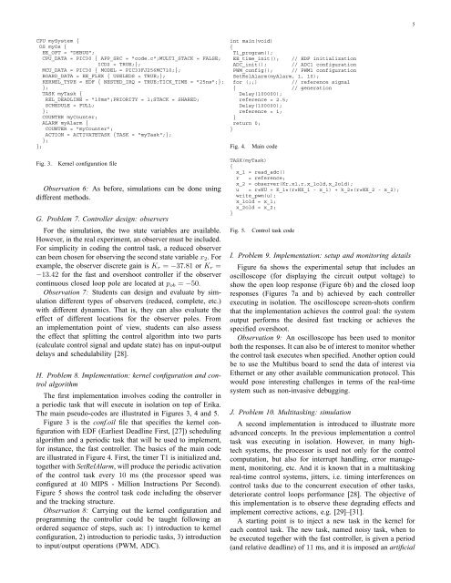
5CPU mySystem {OS myOs {EE_OPT = "DEBUG";CPU_DATA = PIC30 { APP_SRC = "code.c";MULTI_STACK = FALSE;ICD2 = TRUE;};MCU_DATA = PIC30 { MODEL = PIC33FJ256MC710;};BOARD_DATA = EE_FLEX { USELEDS = TRUE;};KERNEL_TYPE = EDF { NESTED_IRQ = TRUE;TICK_TIME = "25ns";};};TASK myTask {REL_DEADLINE = "10ms";PRIORITY = 1;STACK = SHARED;SCHEDULE = FULL;};COUNTER myCounter;ALARM myAlarm {COUNTER = "myCounter";ACTION = ACTIVATETASK {TASK = "myTask";};};};int main(void){T1_program();EE_<strong>time</strong>_init(); // EDF initializationADC_init(); // ADC1 configurationPWM_config(); // PWM1 configurationSetRelAlarm(myAlarm, 1, 10);<strong>for</strong> (;;){ // generationDelay(100000);reference = 2.5;Delay(100000);reference = 1;}return 0;}Fig. 4.Main code// reference signalFig. 3.Kernel configuration fileObservation 6: As be<strong>for</strong>e, simulations can be done usingdifferent methods.G. Problem 7. <strong>Control</strong>ler design: observersFor the simulation, the two state variables are available.However, in the real experiment, an observer must be included.For simplicity in coding the control task, a reduced observercan been chosen <strong>for</strong> observing the second state variablex 2 . Forexample, the observer discrete gain is K r = −37.81 or K r =−13.42 <strong>for</strong> the fast <strong>and</strong> overshoot controller if the observercontinuous closed loop pole are located at p ob = −50.Observation 7: Students can design <strong>and</strong> evaluate by simulationdifferent types of observers (reduced, complete, etc.)with different dynamics. That is, they can also evaluate theeffect of different locations <strong>for</strong> the observer poles. Froman implementation point of view, students can also assessthe effect that splitting the control algorithm into two parts(calculate control signal <strong>and</strong> update state) has on input-outputdelays <strong>and</strong> schedulability [28].H. Problem 8. Implementation: kernel configuration <strong>and</strong> controlalgorithmThe first implementation involves coding the controller ina periodic task that will execute in isolation on top of Erika.The main pseudo-codes are illustrated in Figures 3, 4 <strong>and</strong> 5.Figure 3 is the conf.oil file that specifies the kernel configurationwith EDF (Earliest Deadline First, [27]) schedulingalgorithm <strong>and</strong> a periodic task that will be used to implement,<strong>for</strong> instance, the fast controller. The basics of the main codeare illustrated in Figure 4. First, the <strong>time</strong>r T1 is initialized <strong>and</strong>,together with SetRelAlarm, will produce the periodic activationof the control task every 10 ms (the processor speed wasconfigured at 40 MIPS - Million Instructions Per Second).Figure 5 shows the control task code including the observer<strong>and</strong> the tracking structure.Observation 8: Carrying out the kernel configuration <strong>and</strong>programming the controller could be taught following anordered sequence of steps, such as: 1) introduction to kernelconfiguration, 2) introduction to periodic tasks, 3) introductionto input/output operations (PWM, ADC).TASK(myTask){x_1 = read_adc()r = reference;x_2 = observer(Kr,x1,r,x_1old,x_2old);u = r*NU + K_1*(r*NX_1 - x_1) + k_2*(r*NX_2 - x_2);write_pwm(u);x_1old = x_1;x_2old = x_2;}Fig. 5.<strong>Control</strong> task codeI. Problem 9. Implementation: setup <strong>and</strong> monitoring detailsFigure 6a shows the experimental setup that includes anoscilloscope (<strong>for</strong> displaying the circuit output voltage) toshow the open loop response (Figure 6b) <strong>and</strong> the closed loopresponses (Figures 7a <strong>and</strong> b) achieved by each controllerexecuting in isolation. The oscilloscope screen-shots confirmthat the implementation achieves the control goal: the systemoutput per<strong>for</strong>ms the desired fast tracking or achieves thespecified overshoot.Observation 9: An oscilloscope has been used to monitorboth the responses. It can also be of interest to monitor whetherthe control task executes when specified. Another option couldbe to use the Multibus board to send the data of interest viaEthernet or any other available communication protocol. Thiswould pose interesting challenges in terms of the real-<strong>time</strong>system such as non-invasive debugging.J. Problem 10. Multitasking: simulationA second implementation is introduced to illustrate moreadvanced concepts. In the previous implementation a controltask was executing in isolation. However, in many hightechsystems, the processor is used not only <strong>for</strong> the controlcomputation, but also <strong>for</strong> interrupt h<strong>and</strong>ling, error management,monitoring, etc. And it is known that in a multitaskingreal-<strong>time</strong> control systems, jitters, i.e. timing interferences oncontrol tasks due to the concurrent execution of other tasks,deteriorate control loops per<strong>for</strong>mance [28]. The objective ofthis implementation is to observe these degrading effects <strong>and</strong>implement corrective actions, e.g. [29]–[31].A starting point is to inject a new task in the kernel <strong>for</strong>each control task. The new task, named noisy task, when tobe executed together with the fast controller, is given a period(<strong>and</strong> relative deadline) of 11 ms, <strong>and</strong> it is imposed an artificial