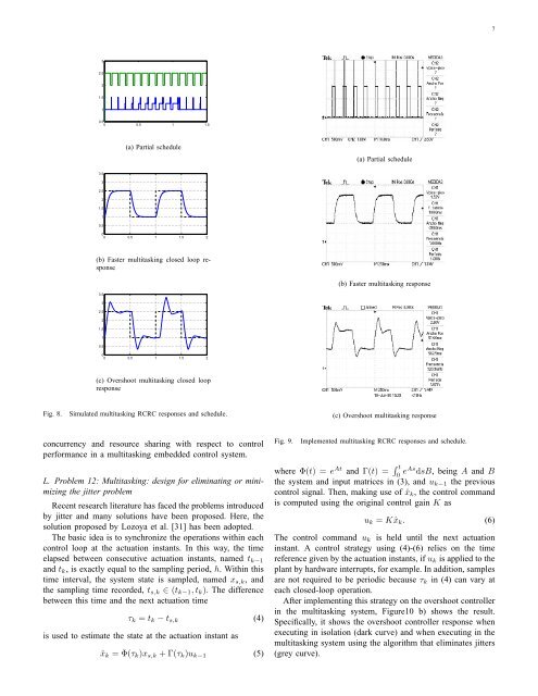
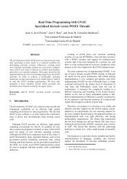
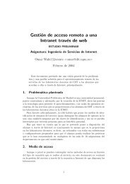
6(a) Fast closed loop response(a) Setup(b) Overshoot closed loop response(b) Open loop responseFig. 7.RCRC responses.Fig. 6.Experiment setup <strong>and</strong> monitoring.execution <strong>time</strong> of 9 ms. The noisy task that goes together withthe overshoot controller has a period <strong>and</strong> relative deadline of110 ms with 90 ms of execution <strong>time</strong>. The simulation of eachmultitasking system was done in the TrueTime simulator [32].Putting together each control task with the corresponding noisytask under EDF results in timing variability (jitter) <strong>for</strong> thecontrol task, as illustrated <strong>for</strong> the first multitasking system inthe schedule of Figure 8a. In this figure, the bottom curverepresents the execution of the fast controller task, whereasthe top curve represents the execution of the noisy task. Ineach graph, the low-level line denotes no-execution (that is,intervals in which the processor is idle), the middle level linedenotes a task ready to execute (i.e., waiting in the readyqueue), whereas the high-level line denotes a task in execution.Note that the control task has a measured execution <strong>time</strong> of0.12 ms, which is much less than the noisy task.Looking at the plant responses in Figures 8 b) <strong>and</strong> c), it canbe appreciated that the fast controller does not exhibit a controlper<strong>for</strong>mance degradation, while the overshoot controller sufferssome degradation: overshoots are bigger, square amplitudediffers, transient response varies, etc. This fact indicates thatthe current control design <strong>for</strong> the fast controller is robustagainst jitters induced by scheduling, while the second oneis more fragile.Observation 10: Adopting an iterative simulation study,students can learn which parameters play an important rolewhen jitters appear. Are shorter sampling periods, or nonovershoottedresponses, a guarantee <strong>for</strong> having robust controldesigns? Which role do deadlines play in reducing jitters? Forfurther questions <strong>and</strong> solutions, see [33] <strong>and</strong> references therein.K. Problem 11. Multitasking: implementation <strong>and</strong> monitoringdetailsThe new implementation requires specifying the noisy taskby modifying the kernel oil file in terms of defining thenew task <strong>and</strong> the associated alarm. Also, the new task hasto be coded: <strong>for</strong>cing an artificial execution <strong>time</strong> is achievedby placing a delay into the code. The main code has to bemodified to configure the new alarm associated to the newtask.After the implementation, in the first multitasking system,it can be verified that scheduling conflicts (as illustrated inthe simulated schedule shown in Figure 8a) may occur, asillustrated in Figure 9a. In this sub-figure, the execution ofthe fast controller task sets an output pin to 0 <strong>and</strong> 1 ateach job start <strong>and</strong> finishing <strong>time</strong>. And the noisy task setsan output pin to 0 <strong>and</strong> 0.5 at each job start <strong>and</strong> finishing<strong>time</strong>. In addition, similar responses <strong>for</strong> the fast <strong>and</strong> overshootcontroller are obtained (see sub-figures 9 b) <strong>and</strong> c)), showingthat the overshoot controller suffers degradation from jitters,while the fast controller shows the same response as it isexecuted in isolation. To illustrative purposes, Figure 10ashows the overshoot controller response when executing inisolation (dark curve) <strong>and</strong> when executing in the multitaskingsystem (grey curve).Observation 11: Undergraduate students may work the experimentup to this problem. It shows the importance of
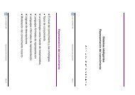
732.521.510.50 0.5 1 1.5(a) Partial schedule(a) Partial schedule3.532.521.510.500 0.5 1 1.5 2(b) Faster multitasking closed loop response(b) Faster multitasking response3.532.521.510.500 0.5 1 1.5 2(c) Overshoot multitasking closed loopresponseFig. 8.Simulated multitasking RCRC responses <strong>and</strong> schedule.(c) Overshoot multitasking responseconcurrency <strong>and</strong> resource sharing with respect to controlper<strong>for</strong>mance in a multitasking embedded control system.L. Problem 12: Multitasking: design <strong>for</strong> eliminating or minimizingthe jitter problemRecent research literature has faced the problems introducedby jitter <strong>and</strong> many solutions have been proposed. Here, thesolution proposed by Lozoya et al. [31] has been adopted.The basic idea is to synchronize the operations within eachcontrol loop at the actuation instants. In this way, the <strong>time</strong>elapsed between consecutive actuation instants, named t k−1<strong>and</strong> t k , is exactly equal to the sampling period, h. Within this<strong>time</strong> interval, the system state is sampled, named x s,k , <strong>and</strong>the sampling <strong>time</strong> recorded, t s,k ∈ (t k−1 ,t k ). The differencebetween this <strong>time</strong> <strong>and</strong> the next actuation <strong>time</strong>τ k = t k −t s,k (4)is used to estimate the state at the actuation instant asˆx k = Φ(τ k )x s,k +Γ(τ k )u k−1 (5)Fig. 9.Implemented multitasking RCRC responses <strong>and</strong> schedule.where Φ(t) = e At <strong>and</strong> Γ(t) = ∫ t0 eAs dsB, being A <strong>and</strong> Bthe system <strong>and</strong> input matrices in (3), <strong>and</strong> u k−1 the previouscontrol signal. Then, making use of ˆx k , the control comm<strong>and</strong>is computed using the original control gain K asu k = Kˆx k . (6)The control comm<strong>and</strong> u k is held until the next actuationinstant. A control strategy using (4)-(6) relies on the <strong>time</strong>reference given by the actuation instants, if u k is applied to theplant by hardware interrupts, <strong>for</strong> example. In addition, samplesare not required to be periodic because τ k in (4) can vary ateach closed-loop operation.After implementing this strategy on the overshoot controllerin the multitasking system, Figure10 b) shows the result.Specifically, it shows the overshoot controller response whenexecuting in isolation (dark curve) <strong>and</strong> when executing in themultitasking system using the algorithm that eliminates jitters(grey curve).