VX-7R Technical Supplement - The Repeater Builder's Technical ...
VX-7R Technical Supplement - The Repeater Builder's Technical ...
VX-7R Technical Supplement - The Repeater Builder's Technical ...

Create successful ePaper yourself
Turn your PDF publications into a flip-book with our unique Google optimized e-Paper software.
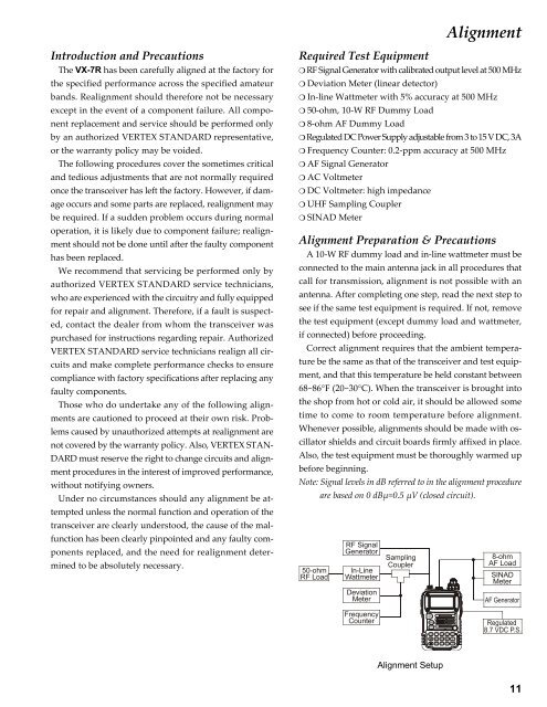
DWAlignmentIntroduction and Precautions<strong>The</strong> <strong>VX</strong>-<strong>7R</strong> has been carefully aligned at the factory forthe specified performance across the specified amateurbands. Realignment should therefore not be necessaryexcept in the event of a component failure. All componentreplacement and service should be performed onlyby an authorized VERTEX STANDARD representative,or the warranty policy may be voided.<strong>The</strong> following procedures cover the sometimes criticaland tedious adjustments that are not normally requiredonce the transceiver has left the factory. However, if damageoccurs and some parts are replaced, realignment maybe required. If a sudden problem occurs during normaloperation, it is likely due to component failure; realignmentshould not be done until after the faulty componenthas been replaced.We recommend that servicing be performed only byauthorized VERTEX STANDARD service technicians,who are experienced with the circuitry and fully equippedfor repair and alignment. <strong>The</strong>refore, if a fault is suspected,contact the dealer from whom the transceiver waspurchased for instructions regarding repair. AuthorizedVERTEX STANDARD service technicians realign all circuitsand make complete performance checks to ensurecompliance with factory specifications after replacing anyfaulty components.Those who do undertake any of the following alignmentsare cautioned to proceed at their own risk. Problemscaused by unauthorized attempts at realignment arenot covered by the warranty policy. Also, VERTEX STAN-DARD must reserve the right to change circuits and alignmentprocedures in the interest of improved performance,without notifying owners.Under no circumstances should any alignment be attemptedunless the normal function and operation of thetransceiver are clearly understood, the cause of the malfunctionhas been clearly pinpointed and any faulty componentsreplaced, and the need for realignment determinedto be absolutely necessary.Required Test Equipment❍ RF Signal Generator with calibrated output level at 500 MHz❍ Deviation Meter (linear detector)❍ In-line Wattmeter with 5% accuracy at 500 MHz❍ 50-ohm, 10-W RF Dummy Load❍ 8-ohm AF Dummy Load❍ Regulated DC Power Supply adjustable from 3 to 15 V DC, 3A❍ Frequency Counter: 0.2-ppm accuracy at 500 MHz❍ AF Signal Generator❍ AC Voltmeter❍ DC Voltmeter: high impedance❍ UHF Sampling Coupler❍ SINAD MeterAlignment Preparation & PrecautionsA 10-W RF dummy load and in-line wattmeter must beconnected to the main antenna jack in all procedures thatcall for transmission, alignment is not possible with anantenna. After completing one step, read the next step tosee if the same test equipment is required. If not, removethe test equipment (except dummy load and wattmeter,if connected) before proceeding.Correct alignment requires that the ambient temperaturebe the same as that of the transceiver and test equipment,and that this temperature be held constant between68~86°F (20~30°C). When the transceiver is brought intothe shop from hot or cold air, it should be allowed sometime to come to room temperature before alignment.Whenever possible, alignments should be made with oscillatorshields and circuit boards firmly affixed in place.Also, the test equipment must be thoroughly warmed upbefore beginning.Note: Signal levels in dB referred to in the alignment procedureare based on 0 dBµ=0.5 µV (closed circuit).50-ohmRF LoadRF SignalGeneratorIn-LineWattmeterDeviationMeterSamplingCoupler8-ohmAF LoadSINADMeterFrequencyCounterAlignment Setup11