

The Spider robot controllers were designed for robots requiring a ...
The Spider robot controllers were designed for robots requiring a ...
The Spider robot controllers were designed for robots requiring a ...

Create successful ePaper yourself
Turn your PDF publications into a flip-book with our unique Google optimized e-Paper software.
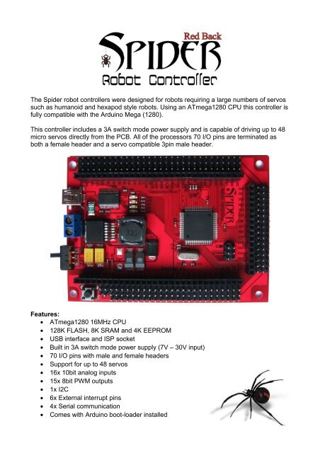
<strong>The</strong> <strong>Spider</strong> <strong>robot</strong> <strong>controllers</strong> <strong>were</strong> <strong>designed</strong> <strong>for</strong> <strong>robot</strong>s <strong>requiring</strong> a large numbers of servossuch as humanoid and hexapod style <strong>robot</strong>s. Using an ATmega1280 CPU this controller isfully compatible with the Arduino Mega (1280).This controller includes a 3A switch mode power supply and is capable of driving up to 48micro servos directly from the PCB. All of the processors 70 I/O pins are terminated asboth a female header and a servo compatible 3pin male header.Features:• ATmega1280 16MHz CPU• 128K FLASH, 8K SRAM and 4K EEPROM• USB interface and ISP socket• Built in 3A switch mode power supply (7V – 30V input)• 70 I/O pins with male and female headers• Support <strong>for</strong> up to 48 servos• 16x 10bit analog inputs• 15x 8bit PWM outputs• 1x I2C• 6x External interrupt pins• 4x Serial communication• Comes with Arduino boot-loader installed
Programming the <strong>Spider</strong> controller:<strong>The</strong> <strong>Spider</strong> controller has been <strong>designed</strong> to be 100% compatible with the Arduino Megaand comes with the Arduino boot loader installed. <strong>The</strong> boot loader allows programs writtenin the Arduino IDE to be uploaded via the USB interface. More in<strong>for</strong>mation about Arduinocan be found here: http://arduino.cc/en/Guide/IntroductionThis manual assumes use of Arduino 0022 or later, which can be downloaded from here:http://arduino.cc/en/Main/Software.A full list of commands can be found here: http://arduino.cc/en/Reference/HomePageCommunications:<strong>The</strong> <strong>Spider</strong> controller has 4x serial ports and 1x I²C interface. Serial interface 0 is used bythe USB interface. Serial ports 1,2 and 3 are available <strong>for</strong> use with devices such as serialinterface LCD’s, Xbee, Blue Tooth and WiFi modules or even other processors.Instructions on how to use these serial interfaces can be found here:http://arduino.cc/en/Reference/Serial<strong>The</strong> I²C interface (SDA pin 20, SCL pin 21) allows the controller to communicate withdevices such as external memory, real time clock (RTC), DC motor <strong>controllers</strong> and more.For the I²C interface to function properly pullup resistors must be used. Some devices willinclude these resistors. If necessary you can enable the internal pullup resistors on pins 20and 21. Instructions on how to use the I²C interface can be found here:http://www.arduino.cc/en/Reference/WireDigital I/O pins:All 70 of the <strong>Spider</strong>s I/O pins can be used <strong>for</strong> simple digital inputs or outputs. By default, allpins except digital pin 13 have their mode set to input. When a pin is in input mode it is in ahigh impedance state (effectively open circuit). Digital pin 13 is set to output by the bootloader and has an LED attached. Although D13 can be used as an input the LED mayinterfere.Use the pinMode() command to change a pins mode between input and output. UsedigitalRead() and digitalWrite() commands to read and write to these pins. Note: Analogpins A0 - A15 are digital pins D54 – D69.Writing a “1” to a digital pin while it is configured as an output will connect that pin toVcc(+5V). Writing a “0” to a digital pin while it is configured as an output will connect thatpin to ground (0V). Each pin is capable of sinking or sourcing up to 40mA maximum butcare must be taken to limit the total current to 200mA. If you wish to drive large numbers ofLEDs or other devices then the output pins should be buffered.Writing a “1” to a digital pin while it is set as an input will enable that pins internal pullupresistor. When enabled, an internal 20K resistor is connected between that pin and Vcc(+5V). Writing a “0” to that pin while configured as an input will disable the pullup resistor.
Analog pins:Pins A0 to A15 are by default analog inputs. Each analog input has 10bit resolution andcan measure the voltage on its pin. Input voltage should not exceed the analog referencevoltage (default value is +5V).<strong>The</strong> input voltage is measured using the analogRead() command. <strong>The</strong> reference voltage isVcc(+5V) by default. <strong>The</strong> reference voltage can be changed using the analogReference()command.PWM outputs:<strong>The</strong> <strong>Spider</strong> controller is capable of generating 8bit resolution pulse width modulatedoutputs on digital pins D2 – D13 and D44 – D46. <strong>The</strong> output of a PWM pin is driven highand then low repeatedly with the duty cycle being adjusted to synthesize an analog output.By adding a simple RC filter to a PWM output a true analog output can be generated.PWM outputs are generated using the analogWrite() command. As the internal timers ofthe processor are used to generate these outputs they may be disabled by othercommands using the same timer. Pin assignments should be planned to avoid conflicts.External interrupts:<strong>The</strong> <strong>Spider</strong> has 6 interrupt pins. Interrupts allow functions to be called only when anexternal event occurs. <strong>The</strong>se pins are useful <strong>for</strong> monitoring devices such as encoders. <strong>The</strong>interrupts and their pins are:Interrupt 0 – D2Interrupt 1 – D1Interrupt 2 – D21Interrupt 3 – D20Interrupt 4 – D19Interrupt 5 – D18More in<strong>for</strong>mation on the interrupt library can be found here:http://arduino.cc/en/Reference/InterruptsUsing the EEPROM memory:<strong>The</strong> <strong>Spider</strong>’s Atmega1280 includes 4K of EEPROM memory that can be used to storein<strong>for</strong>mation while the power is off. More in<strong>for</strong>mation on using the EEPROM library can befound here: http://www.arduino.cc/en/Reference/EEPROM
Using servos:All 70 I/O pins have a servo compatible 3 pin male header. <strong>The</strong> pin closest to the outeredge of the PCB is ground, the center pin is +5V and the inner most pin is the signal. Thispin arrangement is also useful <strong>for</strong> powering sensors.Most miniature and standard servos require between 4.8V and 6V and will work happilydirectly from the PCB. High-po<strong>were</strong>d servos <strong>requiring</strong> 6V or more should be po<strong>were</strong>d viaan external power source or directly from the battery.<strong>The</strong> <strong>Spider</strong> can drive up to 48 servos simultaneously using the Servo library:http://www.arduino.cc/en/Reference/Servo<strong>The</strong> Servo command uses a timer <strong>for</strong> each 12 servos used starting with Timer 5. As thesetimers are also used <strong>for</strong> commands like PWM you need to plan your pin assignments toavoid conflicts.1 to 12 servos use timer 5 disabling PWM on pins 44,45 and 46.13 to 24 servos use timers 1&5 disabling PWM on pins 11,12,44,45 and 46.25 to 36 servos use timers 1,4&5 disabling PWM on pins 6,7,8,11,12,44,45 and 46.37 to 48 servos use timers 1,3,4&5 disabling PWM on pins 2,3,5,6,7,8,11,12,44,45 and 46.Servos can be assigned to any digital pin from D0 - D53.Analog pins A0 - A9 (D54 – D63) can also be used if required.A short tutorial including sample code <strong>for</strong> driving 48 servos can be found here:http://letsmake<strong>robot</strong>s.com/node/25923Shields:<strong>The</strong> female headers on the <strong>Spider</strong> controller are spaced so that a shield can be easilymade from standard prototype PCB. Shields allow you add custom circuitry to yourcontroller.Alternative programming methods:Experienced users may choose to use WinAVR or AVR studio to program their controllerdirectly via the ISP socket. <strong>The</strong> bootloader can be removed which will fee up an additional4K of memory.WinAVR: http://winavr.source<strong>for</strong>ge.net/AVR Studio 5: http://www.atmel.com/microsite/avr_studio_5/


