X-18 Fifth Wheel Hitch System - American RV Company
X-18 Fifth Wheel Hitch System - American RV Company
X-18 Fifth Wheel Hitch System - American RV Company

Create successful ePaper yourself
Turn your PDF publications into a flip-book with our unique Google optimized e-Paper software.
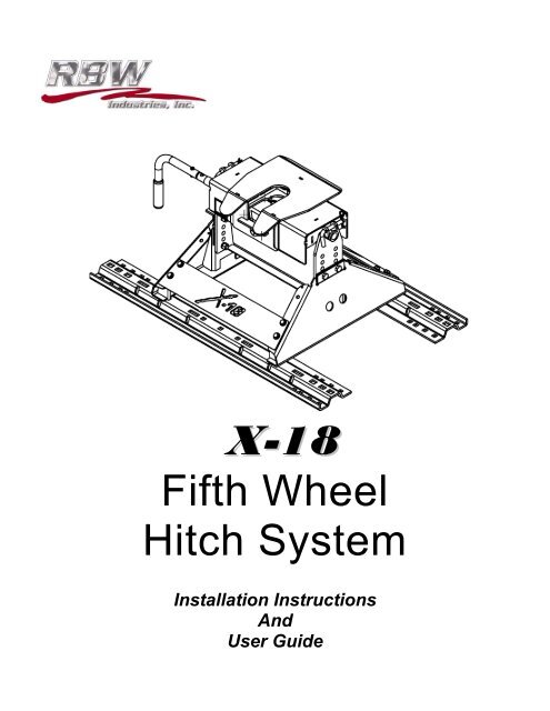
X-<strong>18</strong><strong>Fifth</strong> <strong>Wheel</strong><strong>Hitch</strong> <strong>System</strong>Installation InstructionsAndUser Guide
TABLE OF CONTENTS X-<strong>18</strong>-11-15ContentsINTRODUCTION.......................................................................................................................................................... 2X-<strong>18</strong> PARTS VIEW ................................................................................................................................................................. 3UNPACKING YOUR X-<strong>18</strong> ...................................................................................................................................................... 5HITCH HANDLE ASSEMBLY ................................................................................................................................................ 5HITCH ASSEMBLY ................................................................................................................................................................ 6INSTALLATION NOTES ........................................................................................................................................................ 7ABOUT YOUR X-<strong>18</strong> ............................................................................................................................................................... 8PREPARING FOR FIRST USE .............................................................................................................................................. 8MAINTAINING YOUR X-<strong>18</strong> .................................................................................................................................................... 9OBTAINING WARRANTY SE<strong>RV</strong>ICE ................................................................................................................................... 10X8-1001 HITCH HEAD – EXPLODED VIEW ....................................................................................................................... 11TROUBLESHOOTING.......................................................................................................................................................... 12LIMITED FIVE YEAR WARRANTY ............................................................................................................... 141
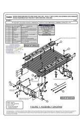
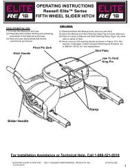
PARTS VIEWX-<strong>18</strong>-11-15X-<strong>18</strong>X-<strong>18</strong> <strong>18</strong>K <strong>Fifth</strong> <strong>Wheel</strong> <strong>Hitch</strong>ing <strong>System</strong>HITCH ASSEMBLYFRAME ATTACH ANGLES3
PARTS VIEWX-<strong>18</strong>-11-15HARDWARE BAG4
ASSEMBLYChapterX-<strong>18</strong>-11-151Unpacking and Assembly1. Unpacking: The X-<strong>18</strong> <strong>Hitch</strong> Assembly ships in three boxes as indicated below. Inspect allparts for damage & verify that all items listed are present.Box 1 Contains (X8-1001) :X-<strong>18</strong> HITCH HEAD (Qty 1)H-220/H-221 <strong>Hitch</strong> Handle w/Grip (Qty 1)Box 2 Contains (X8-1010) :X-2502 Side Body (Qty 2)X-2501 Crossbar (Qty 1)X-2504 Logo Plate (Qty 1)X-2504-BNK Blank Plate (Qty 1)X8-400 Hardware Bag (includes all hardware) (Qty 1)H-240 Short Frame Brackets (Qty 2)H-241 Long Frame Brackets (Qty 2)Box 3 Contains (LR-1020-<strong>18</strong>) :X8-245W Bed Rails (Qty 2)2.<strong>Hitch</strong> Handle Assemblya) Rotate the handle shaft so the bolt hole is oriented at the top.b) Hold the handle with the grip pointed downward and slide the handle onto the handle shaft.c) Fasten the hitch handle using the supplied bolt and nylock nut.5
ASSEMBLYX-<strong>18</strong>-11-153. <strong>Hitch</strong> Assemblya) Place the bed rails (X8-1020) in the bed of the truck approximately 22" from each other,positioned with the bent edge away from the hitch body. (See the <strong>Hitch</strong> Assembly picture onPage 3.)b) Place the side body members (X-2502) into the bed rails with the flat sides facing out. Securethe side body support members to the bed rails using the ½ inch diameter x 6” long clevis pins.Secure the clevis pins using the large hairclips in the hardware bag.c) Slide the crossbar (X-2501) downward between the two body sides. From the outside, insertfour 9/16” diameter bolts into the four holes of each side body and through the appropriatecrossbar mounting holes. Place a lock washer & nut on each bolt & finger tighten.d) Place a 3/8” washer on each of the 3/8” bolts. Install one thru all holes in both of the logoplates (X-2504), and then thru the appropriate holes in the aft facing surfaces of the side bodymembers. Repeat this installation for the blank plate (X-2504-BNK) on the forward facing sideof the hitch. Install a nylock nut on each of the bolts. Do not fully tighten at this time.Caution: Failure to install the both plates will result in a lowered hitch capacity rating.e) Snug down the four 9/16” dia. nuts on each side using an “X” pattern. Torque the bolts to 65 ftlbs. Tighten the 3/8” nylock nuts down and torque to 65 ft-lbs.f) Place the hitch head onto the adjustable yoke crossbar and secure with the supplied ½” X 5”long clevis pins. Check for freedom of movement.g) The X-<strong>18</strong> <strong>Fifth</strong> <strong>Wheel</strong> <strong>Hitch</strong> <strong>System</strong> is now ready for installation.6
INSTALLATIONChapterX-<strong>18</strong>-11-152General Installation NotesInstallation Procedures• For install instructions for your specific truck type – visit out website at:www.rbwindustries.com and click on Product/Install Instructions• Caution: The center of the hitch must be at least 52” from the rear of the cab in order toprevent damage to the tow vehicle and/or coach due to insufficient clearance.• Note: Always mount the frame attachment leg of the frame bracket on the outside of theframe.• Note: Due to variations in chassis suspension component locations it may be necessary toswap long & short frame bracket locations. Always check for proper fit prior to installation.• Note: The ideal location of the center of the hitch is 2” ahead of the axle. Some applicationsdo not allow this due to spring/shock mount location. In these instances the hitch location maybe adjusted fore or aft, but should be no further aft than centered over the axle. Note: Certain2003 Dodge Trucks may require hitch placement behind the axle. In that event,placement can be up to two inches behind the axle. Caution: Moving the hitch too farforward will limit the turning radius of the truck/coach combination.• Note: If a plastic bed liner is installed, the bed liner must be cut out to accommodate the bedrails. This will allow the bed rails to be mounted flush against the bed, and allows installationof required spacers between the bed and bed rails.• Note: Always use spacers H-247 & H-248 to eliminate the risk of crushing or damaging thetruck bed. This is especially important with composite truck beds.• Note: Torque all hardware to 65 ft. lbs.If you have questions regarding the installation or use of our products, please call our TechnicalAssistance Department at 800-451-7821 or 909-591-5359, Weekdays between 8:00 AM and 5:00 PM(Pacific).7
OPERATION AND MAINTENANCEChapterX-<strong>18</strong>-11-15X-<strong>18</strong> Operation and Maintenance3RBW Industries Inc takes great pride in our reputation as an innovative manufacturer of high qualityproducts. We have designed the X-<strong>18</strong> <strong>Fifth</strong> <strong>Wheel</strong> <strong>Hitch</strong> <strong>System</strong> to provide a lifetime of dependableservice. Following the operating instructions and performing the easy maintenance steps listed belowwill help you get the most out of your investment.About Your X-<strong>18</strong>The RBW Industries X-<strong>18</strong> is designed to tow 5 th <strong>Wheel</strong> Trailers with a Gross Vehicle Weight Ratingup to <strong>18</strong>,000 lbs. Exceeding the rated capacity could create an unsafe towing condition and isnot recommended. It has a 4-way swivel head, is height adjustable from 14 to 17 inches in one-inchincrements, and is removed from the bed of the truck by pulling 4 retaining pins.Preparing For First UseYour X-<strong>18</strong> is now installed and you’re anxious to be on your way down the road. You’realmost there, but take a few minutes to ensure your hitch is setup properly for your particulartruck/coach combination by following the steps below.1. Verify the crossbar is installed to provide a minimum of 5-1/2” clearance between the bottom ofthe trailer nose and the top of the truck bedsides, and allows for a level-towing attitude of thecoach. If necessary, adjust the crossbar to the proper height, and re-torque the fasteners to 65ft. lbs.2. Ensure the coach wheels are blocked front & rear & that the rear stabilizer jacks are fullyretracted.3. Level the coach so that the bottom plate of the kingpin box is level with the tabletop or“horseshoe” plate on the top of the hitch head.4. Rotate the handle of the hitch 90 degrees so that the handgrip is pointing straight back & pullthe handle out until the slide bar is held open by the silver trip mechanism.5. Slowly back the truck so that the bottom plate of the kingpin box slides onto the tabletop & thekingpin slides fully into the throat of the hitch head. Set the parking brake of the truck & placethe transmission into park.6. Visually verify the slidebar has closed behind the kingpin and the kingpin box is resting on thetabletop. Positively lock the slidebar by rotating the handle clockwise so the handgrip ispointing straight down at the bed of the truck.8
OPERATION AND MAINTENANCEX-<strong>18</strong>-11-157. Attach the electrical connector to the proper receptacle in accordance with your coach ownersmanual. Using the provided carabiner, attach the trailer breakaway cable to the top hole onthe hitch side riser. Remove the blocks from the wheels of the coach and double check thatthe hitch is properly attached to your coach.Once at your destination, follow these simple steps to properly uncouple your coach fromyour X-<strong>18</strong>.1. Block your coach wheels front & rear.2. If necessary, start your truck & back up against the kingpin to relieve pressure on the slidebar.Set the parking brake, put the transmission into park and then turn off your vehicle.3. Extend the front landing gear of the coach until the weight of the coach is just off of thetabletop of the hitch. Do not exceed 1/16” gap between the bottom plate of the kingpin box andthe tabletop of the hitch. Caution: Raising the coach too high while still connected candamage the hitch head as well as components of your coach. Do not extend the rearstabilizers of the coach prior to or during uncoupling.4. Disconnect the electrical and breakaway connectors in accordance with your coach owner’smanual. Rotate the handle of the hitch 90 degrees so that the handgrip is pointing straightback, then pull the slide bar all the way open. Lock the hitch handle in the open position byrotating it clockwise 90 degrees until the handgrip is pointing down at the bed of the truck.5. You are now ready to pull your truck slowly away from the coach.Maintaining Your X-<strong>18</strong>1. After coupling, always visually check that the slide bar has closed completely across the rearof the kingpin.2. After the first 100 miles, and at least once a year thereafter, inspect all bolts for propertightness. Re-tighten bolts if needed. All fasteners should be torqued to 65 ft lbs.3. Once or twice a week when traveling, apply a few drops of motor oil to the top of the pivot pincollar (H-161). The pivot pins hold the tabletop or "horseshoe" in place on the hitch head andcan be found by locating the hex head bolts on the front and rear of the hitch head.4. Twice a year, apply a light coating of wheel bearing grease to the surfaces of the slide bar thatholds the kingpin in place. For best results, apply the grease with the slide bar in the closedposition. Then pull the slide bar open and apply a light coating of grease to the slide bar shaftthat the handle is attached to. Caution: The slide bar can close with heavy force. Useextreme care to keep fingers, hands, extremities & clothing out of the path of the slidebar. Failure to do so could result in severe injury.5. At least once a year, thoroughly clean and degrease the hitch head assembly. After cleaning,lubricate as mentioned above.9
OPERATION AND MAINTENANCEX-<strong>18</strong>-11-156. Periodically inspect your X-<strong>18</strong> for wear or damage. If excessive wear or damage is found,contact RBW Industries Inc Technical Support Department for assistance at 800-451-7821.Obtaining Warranty ServiceYour warranty statement contains important information. Please take a few moments to turn to therear cover of this guide and familiarize you with RBW Industries, Inc. warranty policy for your X-<strong>18</strong>.For warranty assistance, contact Customer Support at 800-451-7821or 909-591-5359, Weekdays8:00 AM to 4:00 PM (Pacific). 10
OPERATION & MAINTENANCEX-<strong>18</strong>-11-15X8-1001 <strong>Hitch</strong> Head Exploded View 11
TROUBLESHOOTINGX-<strong>18</strong>-11-15TroubleshootingProblem What To Look For Solution<strong>Hitch</strong> is difficult to installand remove from the bedrails.<strong>Hitch</strong> is not assembled correctly.Bed Rails are not parallel witheach other.Refer to <strong>Hitch</strong> Assembly section for properassembly instructions.Use a spacer to hold both bed rails parallelwhile loosening & retightening the carriagebolts.Truck bed collapsing aroundcarriage bolts in bed rails.Install proper spacers between the bed rail andcorrugations. Refer to installation instructionsfor specific directions.<strong>Hitch</strong> will not hook up totrailer kingpin.Incorrect kingpin height.Excessive angle between hitchhead and kingpin.The kingpin plate should be at the same heightas the top of the hitch, or at most 1/16” higher.Level trailer or tow vehicle with blocks underthe wheels. (If not a side-swivel head)<strong>Hitch</strong> is difficult to unhookfrom trailer.Lube disc is too thick.Bent kingpin.Kingpin is resting on the lockingbar, preventing it from slidingopen.Incorrect kingpin height.Excessive angle between hitchhead and kingpin.Disengage side-swivel lockouts. (If applicable)Check thickness of lube disc. It should notexceed 3/16”.Contact your local dealer for replacement.Remove pressure on the locking bar byblocking the trailer wheels in front and behind.With trailer wheels blocked & truck running,place truck in reverse, set the parking brakeand then put truck into park and turn off theengine. This should relieve the pressure onthe locking bar.The kingpin plate should be at the same heightas the top of the hitch, or at most 1/16” higher.Level trailer or tow vehicle with blocks underthe wheels.Locking bar is difficult toclose or open.Lube disc is too thick.Bent kingpin.New hitch head.Disengage side-swivel lockouts. (If applicable)Check thickness of lube disc. It should notexceed 3/16”.Contact your local dealer for replacement.Contact RBW Technical Support forassistance. 12
TROUBLESHOOTINGX-<strong>18</strong>-11-15Locking bar is worn.Inspect locking bar for wear or damage. Lookfor a ridge at the front edge of the locking bar.If found, file away the ridge and lubricatelocking bar. Contact RBW Technical Support iflocking bar is damaged rather than worn.Locking bar does not lockinto the open position.Lack of lubrication.Missing spring on tripmechanism.Missing or damaged tripmechanism.Lubricate locking bar and pull handle with alight coating of grease on all contact surfaces.Contact RBW Industries Technical Support forreplacement spring.Inspect trip mechanism. The trip mechanismshould not be bent & the spring should beattached & have good tension.Side swivel lockout camhandle does not staylocked in the keyway.Handle retaining screw & nutloose.Tighten screw & nut as instructed in themaintenance section of the owner's manual.Tabletop distorted/crackingat the pivot point.Wear & TearReplace tabletop assembly and keeplubricated as instructed in the maintenancesection of the owner's manual. 13
WARRANTYX-<strong>18</strong>-11-15RBW INDUSTRIES, INC.X-<strong>18</strong> <strong>18</strong>K FIFTH WHEEL HITCH SYSTEMLIMITED FIVE YEAR WARRANTYRBW Industries, Inc. warrants the X-<strong>18</strong> <strong>18</strong>K <strong>Fifth</strong> <strong>Wheel</strong> <strong>Hitch</strong> <strong>System</strong> against defects in material andworkmanship under normal use and service, ordinary wear and tear excepted, for Five Years from thefirst date of purchase at retail. Any part found to have a defect in material or workmanship, will berepaired or replaced at the option of RBW when returned to RBW with transportation chargesprepaid. This warranty does not cover the condition, durability or appearance of the product finish.If the hitch is damaged as a result of improper installation, alteration, vehicle accident, misuse orunreasonable use, including but not limited to, loading the product beyond the factory rated loadcapacity, RBW shall not be required to repair or replace such product. In every case, this warrantycovers only the defective part and does not provide for reimbursement of the retail price of the part orlabor charges.RBW shall not be liable for any incidental or consequential damages for breach of any express orimplied warranty on any RBW product.There are no warranties that extend beyond the description of the face hereof. RBW is extending noother warranties, express or implied, nor any warranties of merchantability or fitness for a particularpurpose. Any such warranties of merchantability or fitness for a particular purpose are expresslyexcluded.This warranty is designed and intended to fully comply with the requirements of the Magnusson-MossWarranty Act and all regulations issued by the Federal Trade Commission in connection therewith. Itis not intended to violate any state law or regulation containing more stringent requirements, and suchrequirements automatically become part of this warranty insofar as required by that act.The owner has available the legal remedies provided by the Magnusson-Moss Warranty Act, PublicLaw 93-637, 99 STAT.2<strong>18</strong>3-2193: 15 U.S. Code, Secs 23021-2312, and any applicable statestatutes.RBW INDUSTRIES, INC.5740 Schaefer Avenue • Chino, CA 91710909.591.5359 • 800.451.7821 • Fax 909.591.6730www.rbwindustries.com 14