Reese Hitch Install Instructions - Michigan Truck Spring
Reese Hitch Install Instructions - Michigan Truck Spring
Reese Hitch Install Instructions - Michigan Truck Spring

You also want an ePaper? Increase the reach of your titles
YUMPU automatically turns print PDFs into web optimized ePapers that Google loves.
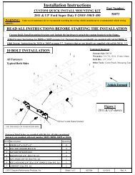
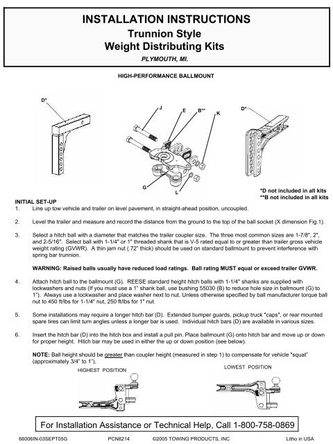
INSTALLATION INSTRUCTIONSTrunnion StyleWeight Distributing KitsPLYMOUTH, MI.HIGH-PERFORMANCE BALLMOUNTD*JEB**KD*INITIAL SET-UP1. Line up tow vehicle and trailer on level pavement, in straight-ahead position, uncoupled.GL*D not included in all kits**B not included in all kits2. Level the trailer and measure and record the distance from the ground to the top of the ball socket (X dimension Fig.1).3. Select a hitch ball with a diameter that matches the trailer coupler size. The three most common sizes are 1-7/8", 2",and 2-5/16". Select ball with 1-1/4" or 1" threaded shank that is V-5 rated equal to or greater than trailer gross vehicleweight rating (GVWR). A thin jam nut (.72” thick) should be used on standard ballmount to prevent interference withspring bar trunnion.WARNING: Raised balls usually have reduced load ratings. Ball rating MUST equal or exceed trailer GVWR.4. Attach hitch ball to the ballmount (G). REESE standard height hitch balls with 1-1/4" shanks are supplied withlockwashers and nuts (If you must use a 1” shank ball, use bushing 55030 (B) to reduce hole size in ballmount (G) to1”). Always use a lockwasher and place washer next to nut. Unless otherwise specified by ball manufacturer torque ballnut to 450 ft/lbs for 1-1/4" nut, 250 ft/lbs for 1" nut.5. Some installations may require a longer hitch bar (D). Extended bumper guards, pickup truck "caps", or rear mountedspare tires can limit turn angles unless a longer bar is used. Individual hitch bars (D) are available in various sizes.6. Insert the hitch bar (D) into the hitch box and install a pull pin. Place ballmount (G) onto hitch bar and move up or downfor proper height. <strong>Hitch</strong> bar may be used in either the up or down position (see below).NOTE: Ball height should be greater than coupler height (measured in step 1) to compensate for vehicle "squat”(approximately 3/4” to 1”).LOWEST POSITIONHIGHEST POSITIONFor <strong>Install</strong>ation Assistance or Technical Help, Call 1-800-758-086966006IN-03SEPT05G PCN8214 ©2005 TOWING PRODUCTS, INC Litho in USA
For vehicles with air springs, air shocks or automatic leveling system, check vehicle owners manual. Unless otherwisespecified, level the vehicle with the vehicle loaded as it will be when towing before setting ball height and attachingtrailer.PRELIMINARY BALLMOUNT ADJUSTMENT1. <strong>Install</strong> hardware in lower hole of ballmount as shown. Tighten nut enough to prevent easy rotation of ballmount.2. Determine spring bar height "Y" using table below. Insert spring bar and trunnion into the ball mount. Swing bar outwardto the same angle as when connected to trailer. Lift up on bar to remove slack. Tilt ball mount for proper "Y” dimensionat end of spring bar.SPRING BAR HEIGHT (Y)COUPLER HEIGHTX15" TO 18"18" TO 20"20" TO 22"22" TO 24"24" TO 26"COUPLER STYLEA B C7" 4-1/2" 5-1/2"8" 5-1/2" 6-1/2"9" 6-1/2" 7-1/2"10" 7-1/2" 8-1/2"11' 8-1/2" 9-1/2"Y* ADD 1” TO Y DIMENSION FOR NON-INTEGRATED CAM SPRING BARS.3. The ballmount (G) is adjustable through a 15° angle. Each step is approx. 1" (approx. 8" overall) at endof spring bar.HIGH-PERFORMANCE BALLMOUNT ADJUSTMENT15°EQUAL NUMBER OFTEETH MUST SHOWTEETH MUSTBE PARALLEL<strong>Install</strong> one adjustment washer (E) on 3/4" X 5" bolt (J) and insert bolt in upper slot in ballmount. Use hole and indexposition required to locate the ballmount at the proper angle. <strong>Install</strong> second adjustment washer using same hole andindex position as first washer, then add lockwasher, and nut. Torque the two nuts (K) to 300 ft/lbs. If proper torquewrench is not available, torque nuts to 150 ft/lbs then turn nuts an additional 1/4 turn. Do not lubricate the threads.<strong>Install</strong> longer 3/4” bolt (J) with two serrated washers (E) as shown. <strong>Install</strong> lockwasher (L) and nut (K), but allow spacefor washers to be positioned and aligned. Align the washers as shown, hold in position, and tighten nut.CAUTION: Washer MUST BE aligned parallel with teeth on ballmount. Re-check washer alignment after nut istightened. Equal number of teeth must show at top and bottom. Teeth can be stripped when loaded if not properlyaligned.66006IN-03SEPT05G PCN8214 ©2005 TOWING PRODUCTS, INC Litho in USA2
INITIAL HOOK UPNOTE: Car and trailer should be loaded and ready for travel before final leveling.1. Pick reference points on front and rear wheel wells. Measure and record distance to pavement.Front wheel well to pavement ___________________ Rear wheel well to pavement __________________.2. Attach chains to spring bars using U-bolts, flat washers, and locknuts. Let 2-3 threads protrude below locknut. Chainmust not bind.STANDARD SPRING BARINTEGRATED CAM SPRING BAR3. Using tongue jack lower coupler onto ball and close coupler latch.4. Hold the spring bar away from you (trunnion ribbed side up). Set the bottom knob of the trunnion into the lower socket ofthe ballmount (G) and slide the knob into the top slot of the ballmount. The spring bars will fit on either side as they arenot made right or left handed.5. Position the snap up brackets on trailer"A" frame so that the chain on the end ofthe spring bar is approximately vertical.Turn 1/2 X 3-1/2 bolt until it contacts frame.Then tighten 1/4 turn with wrench. DO NOTOVERTIGHTEN.6. Raise trailer tongue and rear of car withjack. Lower yoke of snap up bracket untilit is parallel with the ground, and slip theclosest link over the hook (If there areless than 5 links between hook and u-boltadjust ballmount angle rearward, and repeatprocedure). With the snap up brackethandle over the yoke, raise until yokehas passed “over-center”. Slide the safetypin through the small hole to lock the yokein place. Repeat for other side.PLACE CLOSESTLINK ON HOOKSNAP UPHANDLE7. Lower jack. Re-measure front and rear wheel wellreference points (vehicle should settle evenly, withinFig.2about 1/2 inch). If front has settled more than rear,increase the number of chain links between yoke hook and spring bar. If there are no more links, the angle of the headassembly must be decreased. The trailer must be uncoupled and the upper bolt removed from the head assembly.The head assembly is then pivoted up as appropriate. Reassemble. If rear has settled more than front, reduce thenumber of links between hook and spring bar. It is preferred that rear of vehicle settle the same or more than the front.Check to see if trailer is level, if not, you may need to re-adjust ballmount angle and / or position.Check to see that there is room for the bar and chain to move when turning a corner.NOTE: Some surge brakes will not work with weight distributing hitches. Check with manufacturer. Do not usesway control with surge brakes.LUBRICATION1. Lubricate the ballmount sockets and spring bar trunnions to prevent rapid wear. When hooking-up, place one drop of oilon the top and a second drop on forward side of upper trunnion. Place a third drop on the rear side of lower trunnionbefore inserting trunnion into ballmount. Use a heavy oil such as "REESE ON THE BALL". Don't forget to lubricate thehitch ball with one or two drops also. Trunnions should be lubricated each towing day. It is not necessary to unhook thespring bars however, as there are two oil holes in the ballmount top plate for upper trunnion lubrication. Lubricate lowertrunnions with one drop at contact point between trunnion and lower socket. Excess oil, dirt, and grit should be wipedout whenever trailer is uncoupled.66006IN-03SEPT05G PCN8214 ©2005 TOWING PRODUCTS, INC Litho in USA3
WARNINGS: LOADED BALL HEIGHT SHOULD NEVER BE GREATER THAN UNCOUPLED BALL HEIGHT. Front wheel overload and loss of rear wheel traction canresult, and can lead to unstable handling, reduced braking ability, and a tendency to "jackknife" when turning and braking at the same time. IF LOADED BALL HEIGHT ISGREATER THAN UNCOUPLED HEIGHT, reduce take-up on spring bar chains and re-measure until proper height is obtained.DO NOT TOW MULTIPLE TRAILERS: Do not attempt to tow any type of trailer behind another trailer. Towing multiple trailers may cause severe instability, loss ofcontrol and/or structural failure, and may result in vehicle accident, property damage and personal injury. Towing multiple trailers is illegal in many jurisdictions.FRONT-WHEEL-DRIVE VEHICLES: DO NOT ATTEMPT TO HOOK-UP OR TOW WITH REAR WHEELS OF TOWING VEHICLE REMOVED. Severe structural damageto towing vehicle, hitch, and trailer may result. A towing vehicle/trailer combination cannot be controlled adequately unless the towing vehicle's rear wheels are carryingtheir share of the load.MAINTENANCE: Keep trunnions and sockets in head assembly free of dirt and well lubricated. Excessive wear in this area may indicate overload or inadequatelubrication. Some elongation of socket openings "seat in" is normal.Keep head assembly exterior clean, especially the trunnion sockets. Do not allow dirt or stones to lodge between trunnions and head.Keep hitch painted to prevent rust and maintain a good appearance. (Do not paint over labels)AT THE BEGINNING OF EVERY TOWING DAY:• Add drop of oil at trunnion contact areas with ball mount.• Clean ball and coupler socket and coat ball lightly with grease.• Check spring bar chains and U-bolts for wear. Replace before they become worn halfway through.• Check to see that all bolts are properly tightened and hitch pin and clip are securely in place.• Check to see that electrical hookups are in working order, and that safety chains are connected.TOWING TIPSDRIVING: Good habits for normal driving need extra emphasis when towing. The additional weight affects acceleration and braking, and extra time should be allowed forpassing, stopping, and changing lanes. Signal well in advance of a maneuver to let other drivers know your intentions. Severe bumps and badly undulating roads candamage your towing vehicle, hitch, and trailer, and should be negotiated at a slow steady speed. IF ANY PART OF YOUR TOWING SYSTEM "BOTTOMS" OUT, OR IFYOU SUSPECT DAMAGE MAY HAVE OCCURED IN ANY OTHER WAY, PULL OVER AND MAKE A THOROUGH INSPECTION. CORRECT ANY PROBLEMSBEFORE RESUMING TRAVEL.CHECK YOUR EQUIPMENT: Periodically check the condition of all your towing equipment and keep it in top condition.TRAILER LOADING: Proper trailer loading is important. Heavy items should be placed close to the floor near the trailer axle. The load should be balanced side-to-sideand firmly secured to prevent shifting. Tongue weight should be about 10-15 percent of the gross trailer weight for most trailers. Too low a percentage of tongue weightwill often produce a tendency to sway. Excess weight on the tongue can also lead to sway and damage hitch and / or tow vehicle.SWAY CONTROLS: A sway control can help minimize the affects of sudden maneuvers, wind gusts, and buffeting caused by other vehicles. Use of a sway control isrecommended for trailers with large surface areas, such as travel trailers.TIRE INFLATION: Unless specified otherwise by the towing vehicle or trailer manufacturer, tires should be inflated to their maximum recommended pressure.TOWING VEHICLE AND TRAILER MANUFACTURERS' RECOMMENDATIONS: Review the owners' manuals for your towing vehicle and trailer for specificrecommendations, capacities, and requirements.POLE TONGUE TRAILERS: If your trailer has a straight tongue (instead of an A-frame tongue), it will be necessary to use a pole tongue adapter. This adapter attachesto the trailer tongue, providing a place to attach the snap up brackets.PASSENGERS IN TRAILERS: Trailers should NOT be occupied while being towed, under any circumstances.TRAILER LIGHTS, TURN SIGNALS, AND ELECTRIC BRAKES: Always hook up trailer lights, turn signals, electric brakes and break-away switch connection (if soequipped) even for short trips.REMOVE HITCH WHEN NOT TOWING: Remove hitch from towing vehicle receiver when not towing, to prevent contamination of head sockets, reduce chance ofstriking hitch on driveway ramps or other objects, and minimize damage in the event of a rear-end collision.LIMITED WARRANTY<strong>Hitch</strong>es - Custom Receivers - Sway Controls<strong>Reese</strong> warrants its <strong>Hitch</strong>es, Custom <strong>Hitch</strong> Receivers, and Sway Controls from date of purchase against defects in material and workmanship under normal use andservice, ordinary wear and tear excepted, for the ownership life of the original consumer purchaser.<strong>Reese</strong> will replace FREE OF CHARGE any part which proves defective in material or workmanship when presented to any <strong>Reese</strong> dealer, <strong>Reese</strong> Warehouse orreturn to factory. TRANSPORTAION CHARGES PREPAID, at the address below.THIS WARRANTY IS LIMITED TO DEFECTIVE PARTS REPLACEMENT ONLY.LABOR CHARGES AND/OR DAMAGE INCURRED IN INSTALLATION OR REPLACEMENT AS WELL AS INCIDENTAL AN CONSEQUENTIAL DAMAGESCONNECTED THEREWITH ARE EXCLUDED.Some states do not allow the exclusion or limitation of incidental or consequential damages, so the above limitation or exclusion may not apply to you.Any damage to the <strong>Hitch</strong>, Custom <strong>Hitch</strong> Receiver, and Sway Control as a result of misuse, abuse, neglect, accident, improper installation, or any use violative ofinstructions furnished by us, WILL VOID THE WARRANTY.This warranty gives you specific legal rights, and you may also have other rights which vary from state to state. In the event of a problem with warranty service orperformance, you may be able to go to a small claims court, or a federal district court.REESE Products, Inc.51671 State Road 19-N, Elkhart, IN 46514REESE Products of Canada, Ltd.475 Wyecroft Road, Oakville Ontario, Canada L6K2H266006IN-03SEPT05G PCN8214 ©2005 TOWING PRODUCTS, INC Litho in USA4