OPERATING INSTRUCTIONS Reese® Elite ... - CatalogRack.com
OPERATING INSTRUCTIONS Reese® Elite ... - CatalogRack.com
OPERATING INSTRUCTIONS Reese® Elite ... - CatalogRack.com

You also want an ePaper? Increase the reach of your titles
YUMPU automatically turns print PDFs into web optimized ePapers that Google loves.
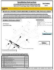
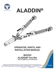
<strong>OPERATING</strong> <strong>INSTRUCTIONS</strong>Reese® <strong>Elite</strong> SeriesFIFTH WHEEL SLIDER HITCHDEALER/INSTALLER:(1) Provide this Manual to end user.(2) Physically demonstrate hitching and unhitchingprocedures in this Manual to end user.(3) Have end user demonstrate that he/sheunderstands procedures.Hitch HandlePivot Pin ZerkEND USER:(1) Read and follow this Manual every time you use hitch.(2) Save this Manual and Hitch Warning Hang Tag for future reference.(3) Pass on copies of Manual and Hitch Warning Hang Tag to any otheruser or owner of hitch.(4) Never remove hitch warning decals as shown in Figure 19 in thismanual. If damaged, contact Cequent Performance Products, Inc.(1-888-521-0510) for free replacement.Skid PlateJaw To HoldKing PinRampSlider HandleFor Installation Assistance or Technical Help, Call 1-888-521-0510N30070OP-12JAN11F PCN14334 ©2011 CEQUENT PERFORMANCE PRODUCTS, INC LITHO IN USAFor Kit 300701
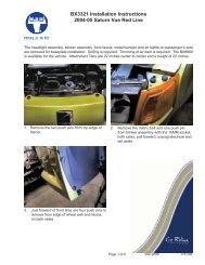
3. Using trailer jacks, adjust trailer height following the directions in the trailer manual so that the bottom oftrailer pin box (“A” Figure. 1) is ½ to 1 inch below skid plate (See “B” in Figure 1). During the hitchingmaneuver, the bottom of the trailer pin box should <strong>com</strong>e in contact with skid plate ramp (“C” in Figure 1).Hitch Skid Plate (B)Bottom of Pin Box (A)1/2” to1” BelowHitch Skid Plate (B)Bottom of Pin Box (A)Bottom of PinBox AboveHitch Skid PlateSkid Plate Ramp (C)Figure 1 CorrectFigure 2 WrongWARNING:Failure to follow this instruction may result in king pin being too high and <strong>com</strong>ing to rest on top of closed jaws or not<strong>com</strong>pletely inside jaws. (See Figure 2). This could result in trailer separating from hitch. Trailer separation may result indeath or serious injury if anyone is under the trailer or between truck and trailer when separation occurs.4. Remove bail pin (see Figure 3). Then pull handle out and rearward to hold openNOTE: Hitch jaw must be in the open position for king pin to enter the hitch.HandleBail Pin HoleHitch Jaw (Shown in OPEN Position)Bail PinPull handle out andlatch to the rear toopen hitch jawFigure 3King pin5. With handle in the open position (See Figure 3), back truck slowly into trailer. As king pin <strong>com</strong>pletely enters head,jaw will spring closed around king pin and handle will return to the closed position. If the handle does not return tothe closed position, then try to push the handle back to theclosed position. If handle doesnot return to the closed positionHandlethen move the truck slightly forwardor rearward until the handle returnsto the closed position (See Figure 4).Figure 4Hitch Jaw (Shown in CLOSED Position)N30070OP-12JAN11F PCN14334 ©2011 CEQUENT PERFORMANCE PRODUCTS, INC LITHO IN USAFor Kit 300703
6. With all trailer wheels still firmly blocked, landing gear still resting on firm ground and supporting trailer weight, and truckstationary and in park with emergency brake on: visually check that bottom of pin box is resting on top of the hitch.THERE SHOULD BE NO SPACE BETWEEN THESE SURFACES (See Figure 5). If space exists, (See Figure 6)trailer has not been properly hitched. h DO NOT TOW! Instead, repeat above steps until trailer is properly hitched. h DO NOT PLACE ANY PART OF BODY UNDER TRAILER TO PERFORM THIS INSPECTION!High PINNo SpaceFigure 5 Figure 6CorrectWRONG7. Place bail pin through bail pin holes in the handle and base plate to make sure the hitch jaw is lockedclosed. IF FLAG BLOCKS HOLE FOR BAIL PIN, TRAILER HAS NOT BEEN PROPERLYCONNECTED TO HITCH. DO NOT TOW! Repeat above steps until trailer is properly hitched. (SeeFigure 7)Bail PinHandleBail pin placementHole for Bail PinKing PinFlagBase plateJaw closedFigure 7N30070OP-12JAN11F PCN14334 ©2011 CEQUENT PERFORMANCE PRODUCTS, INC LITHO IN USAFor Kit 300704
8. With:•All trailer wheels still firmly blocked in front and behind each tire, and•Trailer landing gear still resting on firm ground and supporting trailer weight, and•Truck stationary and with emergency brake on.Connect electrical cable between truck and trailer, connect breakaway switch cable from pin box to apermanent part of truck, and raise tailgate of truck.WARNING:Failure to follow this instruction may result in king pin being too high and <strong>com</strong>ing to rest on top of closed jaws ornot <strong>com</strong>pletely inside jaws. (See Fig. 8). This could result in trailer separating from hitch. Trailer separation mayresult in death or serious injury if anyone is under the trailer or between truck and trailer when separation occurs.Figure 8WRONGWARNING:•Connection for trailer wiring should be in the side of the truck bed between the driver’s seat and thewheel well for the back truck axle•Installation of connection rearward of the wheel well may result in user placing body between truckand trailer. ALWAYS, AVOID PUTTING BODY UNDER TRAILER OR BETWEEN TRUCK AND TRAILER!•If you need to place any part of your body under trailer or between truck and trailer:• All trailer tires MUST be blocked in front and behind each tire AND• Trailer landing gear MUST be resting on firm ground AND• Truck MUST be stationary, in park, with emergency brake on!N30070OP-12JAN11F PCN14334 ©2011 CEQUENT PERFORMANCE PRODUCTS, INC LITHO IN USAFor Kit 300705
PULL TESTWARNING:Failure to perform pull test may result in death or serious injury1. With all trailer wheels still firmly blocked, and2. Trailer landing gear still resting on firm ground and supporting trailer weight and,3. Truck stationary and with emergency brake on:4. Make sure no one is between truck and trailer, Return to cab of truck and release truck’s emergency brake.Apply trailer brakes. Try to pull trailer slowly forward with the truck. If the trailer is properly hitched, the wheelblocks and trailer brakes should keep the truck from moving forward.NOTE: If trailer is not properly hitched, trailer will separate from hitch and truck will move forwardleaving trailer behind. If you followed all previous steps, the trailer will not drop or fall andyou will easily be able to repeat the Hitching Procedure.WARNING:Failure to keep wheels blocked and landing gear down could result in trailer suddenly movingor falling. This could result in death or serious injury!5. After successfully performing above steps, fully raise trailer landing gear (see trailer manual).6. Check and inspect all electrical circuits for proper operation. (Clearance lights, turn signals, stop lights, etc.).7. Remove and store all trailer wheel blocks.UNHITCHING PROCEDURE:PERFORM THE FOLLOWING IN THIS ORDER:1. Make sure truck is in park with emergency brake on.2. Place blocks firmly against front and rear of each trailer wheel to prevent any possible forward or rearwardmotion.3. Using trailer jacks, lower trailer landing gear following the directions in the Trailer Manual until feet of landinggear are resting on firm ground.WARNING:Trailers that are not stable or properly hitched can fall and cause death or serious injury:• All trailer tires MUST be blocked in front and behind each tire AND• Trailer landing gear MUST be resting on firm ground AND• Truck MUST be stationary, in park, with emergency brake on!4. Lower truck tail gate.5. Disconnect power cable and breakaway switch cable between truck and trailer.6. Remove bail pin from hole in handle.7. Pull hitch handle out <strong>com</strong>pletely until it latches in open position o so that king pin is no longer securelye grasped by hitch jaws (see Figure 3). Trailer is now free from hitch and truck. If handle does not pull out,there is probably pressure against the jaw. To relieve this pressure, back the truck slightly or pull the truckslightly forward. Reset truck emergency brake. Then pull hitch handle out <strong>com</strong>pletely until it latches inopen position.N30070OP-12JAN11F PCN14334 ©2011 CEQUENT PERFORMANCE PRODUCTS, INC LITHO IN USAFor Kit 300706
8. AFTER MAKING CERTAIN NO ONE IS STANDING BETWEEN TRUCK AND TRAILER OR IN FRONT OF THETRUCK, drive truck slowly away from trailer.WARNINGWhenever possible, avoid putting body under trailer or between truck and trailerIf you need to place any part of your body under trailer or between truck and trailer:•All trailer tires MUST be blocked in front and behind each tire AND•Trailer landing gear MUST be resting on firm ground AND•Truck MUST be stationary, in park, with emergency brake on!9. KEEP WHEEL BLOCKS IN PLACE. This will keep trailer from moving unexpectedlyMOVE FROM TOWING TO MANEUVERING POSITION1. Position truck and trailer in a straight line on a flat, level area.2. Place truck in “Park” with emergency brake “on”.3. Block front and back of all trailer wheels.4. Lower trailer landing gear so it is resting on firm ground.5. Remove Lock Pin from Slider Assembly.6. Rotate Handle to Unlocked Position-Straight Up. See Figure 9b.7. Return to truck. Release emergency brake. Manually engagetrailer brake and pull truck forward until FIFTH WHEEL Hitchstops and engages in the maneuvering position (see Figure 9c).8. Place truck in “Park” with emergency brake “on”.9. Reinsert Lock Pin and spring retaining clip. ( If the lock pincannot be reinstalled, then the fifth wheel is not fully engaged –Repeat steps 1 – 9 above )Slider Handle inLocked Position10. Perform “PUSH TEST” as follows:A. Manually engage trailer brakes from truck cab.Lock PinFigure 9aB. Back truck into trailer against trailer wheel blocks.Locked Towing PositionC. If the hitch does not move, then the hitch is locked in themaneuvering position.D. If the hitch does move, then the hitch is not locked .DO NOT TOW!. Repeat steps 1 - 10 above.11. Again, place truck in “Park” with emergency brake “on”.12. Examine slider handle position label. Handle should now be over the greenrange on the right side of the label (see Figure 9c). If the slider handle isover the red range on the label, then the hitch is not properly locked in themaneuvering position. DO NOT TOW! Repeat steps 1- 11 above.13. After successfully performing above steps, fully raise trailerSlider Handle in Locked Positionlanding gear (See trailer manual).14. Remove and store all trailer wheel blocks.Slider Handle is Straight UpIn Unlocked PositionLock PinFigure 9bUnlocked Towing PositionFigure 9cLocked Maneuvering PositionN30070OP-12JAN11F PCN14334 ©2011 CEQUENT PERFORMANCE PRODUCTS, INC LITHO IN USAFor Kit 300707
MOVE FROM MANEUVERING TO TOWING POSITIONHandle in Locked Position1. Position truck and trailer in a straight line on a flat, level area.2. Place truck in “Park” with emergency brake “on”.3. Block front and back of all trailer wheels.4. Lower trailer landing gear so it is resting on firm ground.5. Remove Lock Pin from Slider Assembly.6. Rotate Handle to Unlocked Position-Straight Up. See Figure 10b.7. Return to truck. Release emergency brake. Manually engagetrailer brake and back truck rearward until FIFTH WHEEL Hitchstops and engages in the towing position (see Figure 10c).8. Place truck in “Park” with emergency brake “on”.9. Reinsert Lock Pin and spring retaining clip. ( If the lock pincannot be reinstalled, then the fifth wheel is not fully engaged –Repeat steps 1 – 8 above )10. Perform “PULL TEST” as follows:A. Manually engage trailer brakes from truck cab.B. Pull truck and trailer forward against trailer wheel blocks.C. If the hitch does not move, then the hitch is locked in the towingposition.D. If the hitch does move, then the hitch is not locked.DO NOT TOW!. Repeat steps 1 - 10 above.11. Again, place truck in “Park” with emergency brake “on”.Handle is Straight UpIn Unlocked PositionLock Pin12. Examine warning label. l Handle should now be over the greenrange on the left side of the warning label (see figure 10c). If indicatorpin is over red range on warning label, hitch in not properly locked in the towing position.DO NOT TOW! Repeat steps 1-11 above.13. After successfully performing above steps, fully raise trailerlanding gear (See trailer manual).14. Remove and store all trailer wheel blocks.Figure 10aLocked Maneuvering PositionHandle inLocked PositionFigure 10bUnlocked Towing PositionLock Pin Figure 10cLocked Towing PositionN30070OP-12JAN11F PCN14334 ©2011 CEQUENT PERFORMANCE PRODUCTS, INC LITHO IN USAFor Kit 300708
MAINTENANCE:1. Recheck tightness of all hardware every 1000 miles of use. All 5/8” bolts have a torque specification of 170ft-lbsand 1” jam nuts should be box wrench tight (see assembly instruction, 30070N, for more detail).Box wrench tight is when you tighten each jam nut ¼ turn more once there is no vertical play in all theanchor bushing assemblies.See “Before each trip” section in this manual on page 2.2. Anchor assemblies should be lubed every 6 months with lithium grease to keep assemblies movingfreely.3. Lubricate Rollers, Lock Cam, Lock Arm, Slider Rails & Spring on Slider Assemblies every 6 months withlithium grease to keep assemblies moving freely. See Figure 11.LubricateLock ArmLubricateLock Cam & SpringLubricateRollerLubricateRollerFigure 11N30070OP-12JAN11F PCN14334 ©2011 CEQUENT PERFORMANCE PRODUCTS, INC LITHO IN USAFor Kit 300709
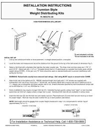
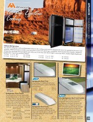
SLIDER HITCH INSTALLATION:1. Remove puck plugs from all (4) of the pucks in the truck bed (Figure 12) and store for use when hitch is removed.2. Set <strong>Elite</strong> Series Slider hitch onto the pucks, and rotate handles into unlocked position(approximately perpendicularwith base rail assembly Figure 13) until hitch drops into pucks on all (4) corners.3. Rotate (4) anchor handles into the locked position(anchor handles parallel with base rail assembly). Figure 14.4. If system has any vertical movement, remove the slider hitch from the pucks. Remove the 3/16” cotter pin, turn theanchor tee pin ½ turn clockwise to tighten or ½ turn counterclockwise to loosen (do this to all 4 mounting points).Replace cotter pin in the system (DO NOT BEND). Figure 15 and 16.5. Repeat steps #2 and #3. Check the hitch for vertical movement.6. If the anchor handles lock in place and there is no vertical movement - pry open the ends of the 3/16” cotter pin andbend them back on themselves to secure. At this point, also bend up (1) tab on each tab washer that best matches upwith a flat on each jam nut. This keeps the jam nut from working loose over time. See Figures 15 and 16. If systemhas vertical movement repeat step #4.7. Place lynch pins / locks through h the anchor handle holes on each side to anchor hitch h into pucks. Figures 14 & 17.8. KEEPING HANDS AND FINGERS AWAY FROM THE PINCH POINTS ON EACH SIDE OF THE HEAD, place headassembly onto the <strong>Elite</strong> Series Slider hitch. Figure 14. Head assembly should tilt rearward on the torsion springs.9. Insert pull pin and clip on each side of the head to attach to the <strong>Elite</strong> Series Slider hitch. Figures 14 & 17.10. Pull up on head to test that all attachments have been <strong>com</strong>pleted properly and hitch is ready to tow. Figure 18.SLIDER HITCH REMOVAL:1. Remove pull pin and clip from each side of the head. Figure 17.2. KEEPING HANDS AND FINGERS AWAY FROM THE PINCH POINTS ON EACH SIDE OF THE HEAD, lift headassembly of <strong>Elite</strong> Series Slider hitch. Figure 14. Store where dirt and debris will not get inside jaw mechanism.3. Remove lynch pin / lock from the anchor handle holes on each side of the <strong>Elite</strong> Series Slider hitch. Figures 14 & 17.Store lynch pins.4. Rotate (4) handles into unlocked position(perpendicular with base rail assembly). Figure 13. Lift each side of hitch outof pucks separately, handles may have to be jiggled slightly to align anchors with puck holes to remove.5. Store hitch in dry place where dirt and debris will not get into anchor assemblies.6. Press puck plugs (packed with mounting kit) into all (4) of the pucks in the truck bed to keep debris out of pucks.Figure 12.Truck BedPuck PlugPuckFigure 12: Puck PlugsAnchor Handle inUnlocked Position<strong>Elite</strong> SeriesSlider hitchBase RailAssemblyFront of TruckPuckTruck BedFigure 13:N30070OP-12JAN11F PCN14334 ©2011 CEQUENT PERFORMANCE PRODUCTS, INC LITHO IN USAFor Kit 3007010
Pinch PointsHead Assembly<strong>Elite</strong> SeriesSlider hitchBase Rail AssemblyAnchor Handle in Locked Positionwith Lynch Pin attachedFigure 14:3/16” Cotter PinAnchor Handle “A” ShownAnchor HandleJam NutAnchor BushingAnchor Tee PinFigure 15AnchorTee PinFigure 16Hole in Anchor Tee PinSlot in Anchor Handle nutAnchor Handle nutAnchor Handle1” Jam NutTab Washer with (1) tab bentup against flat of Jam NutLynch PinPull Pin & ClipFigure 17: HardwareFigure 18: Complete AssemblyN30070OP-12JAN11F PCN14334 ©2011 CEQUENT PERFORMANCE PRODUCTS, INC LITHO IN USAFor Kit 3007011
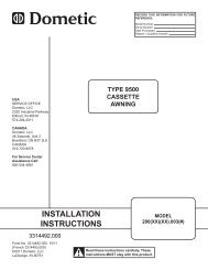
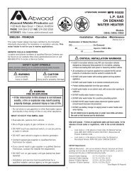
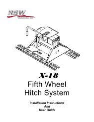
30144Figure 19Ref. # PART QTY. Ref. # PART QTY.1 HEAD ASSEMBLY 1 14 SPRING RETAINING CLIP 32 CENTER SECTION 1 15 LYNCH PIN 23 SLIDER ASSEMBLY - LH & RH 2 16 GRIP, HEAD HANDLE 14 ANCHOR ASSEMBLY 4 17 GRIP, SLIDER HANDLE 1ANCHOR TEE PIN (4) 18 SLIDER HANDLE 1HANDLE "A" (2) & "B" (2) 19 CONNECTOR TUBE 11" JAM NUT (4) 20 SLIDER RAIL 23/16" COTTER PIN (4) 21 5/32" COTTER PIN 2ANCHOR BUSHING (4) 22 SLIDER ASSEMBLY COVER 25 5/8"-11 x 1.5" GRADE 8 HEX HEAD BO4 23 SCREW 86 5/8" LOCK WASHER 4 24 3/8" x 4" BOLT 27 1/4" - 20 x 1.75" BOLT 2 25 3/8" NYLOCK NUT 28 TUBE SPACER 2 26 LOCK PIN 19 TORSION SPRING - LH & RH 2 27 NYLON LANYARD 110 HANDLE TUBE 1 28 3/8" FLAT WASHER 211 3/8" x 1" CARRIAGE BOLT 2 29 BAIL PIN 112 3/8" NUT 2 30 HANG TAG 113 1/2" PULL PIN 2 31 1/4" FENDER WASHER 232 3/8" WASHER 4NOTE: KIT30070 WILLONLY CONTAINPARTS 3,4,17-27 & 32N30070OP-12JAN11F PCN14334 ©2011 CEQUENT PERFORMANCE PRODUCTS, INC LITHO IN USAFor Kit 3007012
NOTESSEVEN YEAR LIMITED WARRANTYCequent Performance Products, Inc. warrants its Reese® <strong>Elite</strong> Series Fifth Wheel Hitches from date ofpurchase against defects in material and workmanship under normal use and service, ordinary wear andtear excepted, for 7 years of ownership to the original consumer purchaser when a Cequent PerformanceProducts, Inc. mounting kit is used.Cequent Performance Products, Inc. will replace FREE OF CHARGE any part which proves defective inmaterial or workmanship when presented to any Cequent Performance Products, Inc. dealer, CequentPerformance Products, Inc. Warehouse or returned to factory. TRANSPORTATION CHARGESPREPAID, at the address below. THIS WARRANTY IS LIMITED TO DEFECTIVE PARTSREPLACEMENT ONLY. LABOR CHARGES AND/OR DAMAGE INCURRED IN INSTALLATION ORREPLACEMENT AS WELL AS INCIDENTAL AND CONSEQUENTIAL DAMAGES CONNECTEDTHEREWITH ARE EXCLUDED.Some states do not allow the exclusion or limitation of incidental or consequential damages, so the abovelimitation or exclusion may not apply to you.Any damage to the Fifth Wheel Hitch as a result of misuse, abuse, neglect, accident, improper installation,or any use violative of instructions furnished by us, WILL VOID THE WARRANTY.This warranty gives you specific legal rights, and you may also have other rights which vary from state tostate. In the event of a problem with warranty service or performance, you may be able to go to a smallclaims court, or a federal district court.Cequent Performance Products, Inc.47774 Anchor Court WestPlymouth, MI. 48170N30070OP-12JAN11F PCN14334 ©2011 CEQUENT PERFORMANCE PRODUCTS, INC LITHO IN USAFor Kit 3007013