Create successful ePaper yourself
Turn your PDF publications into a flip-book with our unique Google optimized e-Paper software.
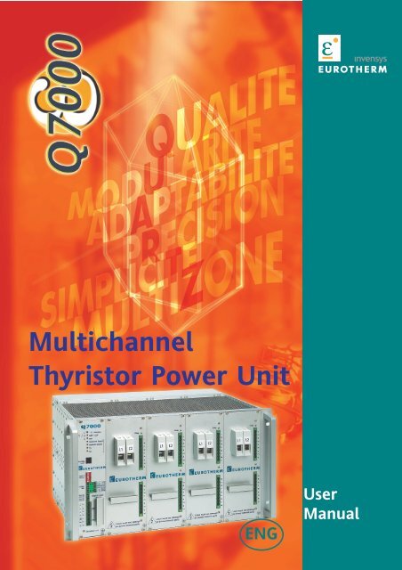
MultichannelThyristor Power UnitENGUserManual
CONTENTSCONTENTSPageEuropean directives and applicable standards 0-2Chapter 1 Q7000 Identification 1-1Chapitre 2 Installation 2-1Chapitre 3 Firing modes - Control - Limitation 3-1Chapitre 4 Alarms 4-1Chapitre 5 Digital Communication 5-1Maintenance 6-1Eurotherm 7-1Q7000 User Manual Réf : HA 028 500ENG - issue 3.0 - 12/2005Q7000 User Manual0-1
European Directives ans applicable standardsThis manual ( Issue 3.0 ) describes the b<strong>as</strong>ic Version and Options of the Q7000 Thyristor Power Unit.EUROPEAN DIRECTIVES AND APPLICABLE STANDARDSCOMPLANCE WITH PRODUCT STANDARDQ7000 products comply with the terms of product standard EN 60947-4-3‘Contactors and motor-starters - AC semiconductor controllers and contactors for non-motor loads’.The number of this standard is indicated on the front panel label.CE LABELLINGQ7000 products, installed and used in accordance with their user manual, bear CE labelling to indicate compliance withthe essential requirements of:• the European Low Voltage Directive 73/23 EEC dated 19 February 1973 amended by 93/68 EEC dated 22 July 1993• the Electromagnetic Compatibility Directive 89/336/EEC dated 3 May 1969 amended by 92/31/EEC dated 28 April 1992 and93/68/EEC dated 22 July 1993.SAFETYThe units have IP20 protection rating <strong>as</strong> defined by standard IEC 60529.External wiring must comply with standards IEC 60364-4-43 and IEC 60943.Copper cables and conductors rated to a temperature of 75°C (167°F) must be used.ELECTROMAGNETIC COMPATIBILITY (EMC) TEST STANDARDSQ7000 products installed and used in accordance with the user manual, are designed for an industrial environment andmust not be used in the home.IMMUNITYThe EMC immunity test standards required by product standard EN 60947-4-3 are given in table 1.Test Type Minimum Level EMC test standardsElectrostatic discharge 4 kV on contact ; 8 kV in air EN 61000-4-2Radiated, radio frequency 10 V/m 80 MHz ≤ f ≤ 1 GHz ; EN 61000-4-3electromagnetic field80% modulation 1 kHz sinusoidalElectrical f<strong>as</strong>t transient / burst 2 kV / 5 kHz EN 61000-4-4Electical surge4 kV line to earth;2 kV line to line. EN 61000-4-5Conducted disturbances 140 dBmV; 150 kHz ≤ f ≤ 80 MHz EN 61000-4-6Voltage dips, short interruptionsand voltage variation 5 s interruptions EN 61000-4-11Table 1 - EMC immunity standards complianceEMISSIONSThe EMC emissions test standards required by product standard EN 60947-4-3 are given in table 2.Emission Type Firing Mode EMC test standardsRadiated, radio frequency All firing modes CISPR 11 Cl<strong>as</strong>s AConducted, radio frequency ‘Burst mode’ and ‘Single-cycle’ CISPR 11 Cl<strong>as</strong>s A Groupe 2Table 2 - EMC emissions standards complianceEMC GUIDETo help you deal with installation-dependent electromagnetic interference effects, Eurotherm provides an ‘Electromagneticcompatibility’ installation guide (ref. HA025464) which sets out best current practice regarding EMC.DECLARATION OF CONFORMITYA CE declaration of conformity is available on request.Q7000 User Manual0-2
IdentificationCHAPTER 11. Q7000 IDENTIFICATIONContentsPage1.1. Driver card description 1-21.2. Power card Description 1-31.3. Technical specifications 1-41.3.1. Product standards and CE labelling1.3.2. Environment1.3.3. Power1.3.4. Control1.3.5. Triacs protection1.3.6. Control 1-51.3.7. Firing modes 1-51.4. Options 1-51.4.1. Thyristor short-circuit and Total Load Failure (GRF)1.4.2. Diagnostic and Partial Load Failure (DLF)1.4.3. Over Temperature1.4.4. Alarm relays 1-61.5. Mechanical <strong>as</strong>pect 1-61.6. User digital Communication1.7. Configurator Digital Communication1.8. Coding 1-7Q7000 User Manual1-1
1.1. DRIVER CARD DESCRIPTIONIdentificationQ7000/- T° / DisableGRF / DLFONNetwork StatusModele StatusTxRxOver temperature Alarm and conductionstopped or inhibition of conductionGRF alarm and/or DLF diagnosticaccording to the LED colourSupply status :Auxilary Power supplyPower Cards Power SupplyUser Digital Communication statusDB9 connector for user communication(ProfiBus Protocol only)iToolsRJ 11 connector for iTools Configurator(ModBus Protocol only)919212345678COM. UserSpeed & AddressDNV-CAN_LMOP / PFPBADIP Switches :Transmission speed selection andproduct address for ModBus protcol onlyDigital communication connectorModBus or ProfiBus protocol9394ShieldCAN_HGND5VP9596V+NCBTBBTADeviceNet protocolENA 640VD 61FAN 600VD 61DigitalinputInputs :Connector for dry contact logic input1a711b2a2b727374OutputRelaysOutput :• Alarm contact terminal block7Vaux 15AuxInput :0V18• External Power supplyterminal blockEN 60947-4-3Q7000 User Manual1-2
1.2. POWER CARD DESCRIPTIONIdentificationPower terminals supply sideDiag.Diagnostic LEDfor the power cardL1L21N2N3N4N5Power terminals supply sideN6N7N8N9NUsers must not attemptto access internal partsUsers must not attemptto access internal partsIn order to ensure the electrical security and the protectiveearth continuity the, all the front pannel screws must beclamped at the right clamping torque (0.5 Nm).Q7000 User Manual1-3
Identification1.3. TECHNICAL SPECIFICATIONS1.3.1. PRODUCT STANDARDS AND CE LABELLINGQ7000 products comply with the terms of product standard EN 60947-4-3‘Contactors and motor-starters - AC semiconductor controllers and contactors for non-motor loads’.The number of this standard is indicated on the front panel label.Q7000 products, installed and used in accordance with their user manual, bear CE labelling to indicatecompliance with the essential requirements of:• the European Low Voltage Directive 73/23 EEC dated 19 February 1973 amended by 93/68 EEC dated 22 July 1993• the Electromagnetic Compatibility Directive 89/336/EEC dated 3 May 1969 amended by 92/31/EEC dated28 April 1992 and 93/68/EEC dated 22 July 1993.IP 20 protection without any added protections, according to EN 60529, defined by IEC 664A fuse on each line is installed inside the rack.1.3.2. ENVIRONMENTUse0 to 45 °C of ambient temperature with a nominal current of 11 A with aderating to 5.5 A for 0 to 60 °C af ambient temperatureThe minimum working temperature is 0 °C at a maximum altitude of 2000 m Max.Storage from -10°C to 70°Pollution Degree 2 acceptable (definied by IEC 60664).AtmosphereNon explosive, non-corrosive, non-conductive.HumidityRH 5% to 95%, non-condensing, non-streaming.1.3.3. POWERNominal Current 11 A at 45 °CNominal Voltage230 V or 115 V (+10 % ; -15 %) standards.For other voltages (24V, 48V and 63.5V) ple<strong>as</strong>e contact Eurotherm.FrequencyUse from 47 to 63 Hz (automatic matching)Dissipated Power≈ 1,3 W per amp and per ph<strong>as</strong>e.CoolingVentilation rack. 115 V or 230 V ; consumption 10 VA.Water cooling in addition to air cooling is necessary for working temperatureof use higher than the ones indicated.Load typeSingle-ph<strong>as</strong>ed load, they can be distibuted among one, two or three ph<strong>as</strong>eaccording to the custommer choiceCategory of UseAC-51. Non-indictive or low inductance loads, furnace resistancesResistive load with low temperature coefficient1.3.4. CONTROLPower supplyControl typeExternal power supply (115 V or 230 V ; +10 %, -15 %), consumption 10 VA.Digital1.3.5. TRIAC PROTECTION• Triacs protection by RC snubbers (each)• General protection of the product by VaristorsQ7000 User Manual1-4
Identification1.3.6. CONTROLControl type V 2 , compensation of supply voltage variationsI 2 , V x I, Open Loop, Vrms ou Irms.Linearity ±1 % (Balanced load and supply)Stability ±1 % (supply variation from +10 % to -15 %)Accuracy ±1 % (Balanced load and supply)1.3.7. FIRING MODESDigital Communication configuration.Zero crossing firing - Burst mode, from 2 to 255 cycles- Single-Cycle (1 b<strong>as</strong>e cycle),- Advanced Single-Cycle, conduction / no conduction by half cycles.1.4. ALARMSNote : Powerering on acts the same way <strong>as</strong> alarm acknoledgement1.4.1. Thyristor Short-Circuit and Total Load Failure (GRF)• Alarm signalling Thyristor Short-Circuit or Total Load Failure• Alarm relay contact signalling (if defined by user for this alarm) :Alarm Relay 1 and/or Alarm Relay 2 (NO or NC see code).These two relays are entirely configurable by the user.• GRF/DLF red LED on front panel shows if on of the power slot h<strong>as</strong> failed andvia SWC and GSW1 status words.1.4.2. Diagnostic and Partial Load Failure (DLF)• Adjustable up to I>30% and V>40% of the nominal current and voltage of the unit.• Failure detection of one element out of two (Consatnt resistance loads)• Alarm relay contact signalling (if defined by user for this alarm) :Alarm Relay 1 and/or Alarm Relay 2 (NO or NC see code).These two relays are entirely configurable by the user• GRF/DLF fl<strong>as</strong>hing orange LED on front panel, showing if one of the power slot h<strong>as</strong> failed,Alarm Relay 1 and/or Alarm Relay 2 (NO or NC see code) if set during configuration andvia SWC and GSW1 status words.Important :Even if the PLF detection is OFF, the TLF detection stays active. The PLF setting request is made with theCommand word 7 with all the currents > 30% of IN, for the load to be monitored. Disabelling the PLF alram isdone by setting the setpiont th 0%.1.4.3. Overtemperature• Conductions stopped if the temperature exceeds the temperature level. Indicated by theT° red LED and alarm relay if selected.Q7000 User Manual1-5
Identification1.4.4. Alarm RelaysTwo alarm relay contacts are available and reconfigurable by the user.Relay contact (0,25 A/230 Vac, 32 Vdc) is closed or open in alarm according to the code.1.5. MECHANICAL ASPECTConstitution The Q7000 is a 19’’ standard rackDriver and Power parts can be bought separately (Kit version)Dimensions Height Width DepthRack 6U (265,9 mm) 19’’ (482,6mm) 295 mmDriver 233,25 mm 12 F (60,96 mm) 220 mmPower 233,25 mm 18 F (91,44 mm) 220 mmCabinet ≤ 2 m 400 mm 600 mmMountingInto a cabinet, from 1 to 3 racks.CoolingWarning ! Only 3 racks can be mounted into a cabinet with the right cooling processWith a current of 11 A per channel, without exceeding 40 °C of ambiant temperature, cooling is <strong>as</strong>suredwith a ventilation unit.If the temprature exceeds 40 °C, water-cooling is necessary in addition to air-cooling, in order tomaitain 40 °C inside the cabinet.The units have a thermal switch in order to avoid over-heating damage if theventilation units fails.Use example for 3 racks into a cabinet (1400*600*400 mm)• Max ambient temperature of 45 °C,11 A of nominal currentMinimum output flow the fan-cooling system must deliver : 3 x 900 m3/h• Max ambient temperature of 60 °C,11 A of nominal current(Water cooling system in addition to the fan-cooling system)Minimum output flow the water-cooling system must deliver : 100 l/h,under 10 bars pressure (T water < 20 °C)1.6. USER DIGITAL COMMUNICATIONFanProtocolModBus RTU, ProfiBus, DeviceNetTransmission Standard RS485, 2 wires (A and B)Q7000ModBus ProtocolTransmission speed 9600 to 19200 bauds (dipswith 1),AddressDip Switches from 2 to 8 selectionCommunication complies with the specification given in ‘GOULD MODICON Protocol Reference Guide PI-MBUS-300 rev J’.ProofiBus ProtocolThe Profibus (Process Field Bus Decentralized Periphery) communication protocol specifications aredefined by the EN 50170 / DIN 19245 / Part3 directives.DeviceNet Protocol** available later1.7. DIGITAL COMMUNICATION CONFIGURATOR ( iTools )Q7000ProtocolModBus®Standard de transmission RS232, 3 wires (Rx, Tx and GND), RJ11 connector, with Eurotherm link reference :2500A/CABLE/CONFIG/RJ11/9PINDF/3MoTransmission speed19200 baudsAddress :1 by defaultFanFanQ7000Q7000 User Manual1-6
CodingCoding : Q7000 1 / 2 / 3 / 4 / 5 / 6 / 7 / 8 / 9 / 101. Number of Channels Code9 Channels 918 Channels 1827 Channels 2736 Channels 362. Nominal Load Voltage - Slot 1 Code115 Volts 115V230 Volts 230V3. Nominal Load Voltage - Slot 2 CodeNo slot 2XXXX115 Volts 115V230 Volts 230V4. Nominal Load Voltage - Slot 3 CodeNo slot 3XXXX115 Volts 115V230 Volts 230V5. Nominal Load Voltage - Slot 4 CodeNo slot 4XXXX115 Volts 115V230 Volts 230V7.Electronic and fan Supply CodeExternal 24 V Supply 24V*External 115 V Supply115VExternal 230 V Supply230V8. Digital Communication CodeModbus® ProtocolMOPProfibus-DP ProtocolPFPDeviceNet ProtocolDNP*9. Relay Configuration - R1 and R2 CodeRelay 1 Relay 2Normally Closed Normally Closed NC-NCNormally Closed Normally Open NC-NONormally Open Normally Closed NO-NCNormally Open Normally Open NO-NOThe standard, out of factory configuration, being NC-NC10. Certification CodeWith CertificateCERTNoneXXXX* Available later6. Fan CodeWith fanFANWithout FanNOFANQ7000 User Manual1-7
InstallationCHAPTER 22. INSTALLATIONContentsPage2.1. Safety during installation (mounting and wiring) 2-22.2. Driver wiring connection diagram 2-32.3. Wiring power connection diagram 2-4Q7000 User Manaual2-1
Installation2. INSTALLATION2.1. SAFETY DURING INSTALLATION (MOUNTING AND WIRING)Danger !• Q7000 must be installed and wired by qualified staff authorised to work on low voltageindustrial electrical facilities.• Load connectors must stay plugged-in, even if they are not used.• Units must be installed in a fan-cooled cabinet, to ensure that condensation and pollution are excluded.We recommend fitting fan-cooled cabinets with a fan failure detection device or a thermal safety cut-out.The cabinet must be closed and connected to the protective earth according to IEC 364 orapplicable national standards.• Units must be mounted with no obstructions above or below the unit which could reduce or hamper air flow.If several units are fitted in the same cabinet, arrange them such that air from one unit is not drawnin by the unit above. Leave a gap of at le<strong>as</strong>t 10 mm between two adjacent units.!Warning !• Nominal currents correspond to use at ambient temperatures.Overheating may cause incorrect operation and may even lead to components being damaged.Danger !• It is the user’s responsibility to wire and protect the facility according to best practice and applicable standards.A suitable device, ensuring that the unit can be electrically isolated from the supply, must beinstalled upline to enable work to be performed safely. Conductor cross-sections should comply withIEC 943. Use only copper cables and wires designed for use at up to 75°C.• Before connecting or disconnecting the unit check that power and control cables and leads areisolated from voltage sources. The protective earth must be connected before any otherconnections are made and should be the l<strong>as</strong>t cable to be disconnected.The protective earth connection terminal is marked with the symbol.In order to ensure the electrical security and the protective earth continuity,all the front panel screws must be clamped at the right clamping torque (0.5 Nm).!Warning !• To ensure that Q7000 comply with Electromagnetic Compatibility requirements, ensure that thepanel to which they are attached is correctly grounded.The ground connection, designed toensure ground continuity, is not in any way a substitute for the protective earth connection.To ensure the protective earth continuity and the electrical safety of the installation, all thefront panel screws must be clamped correctly, at the clamping torque indicated.Q7000 User Manaual2-2
Installation2.2. WIRING DRIVER CONNECTION DIAGRAMQ7000/- T° / DisableGRF / DLFONNetwork StatusModele StatusTxRxRJ 11 configuration connector (iTools) -ModBus protocol only.DB9 connector compatible with ‘F<strong>as</strong>tConnect’ ProfiBus connector type.Digital communication wiring -RS 485 for ModBus & ProfibusprotocolsNote :Wiring for DevicNet protocolcomplies with the actualdirectives used.iTools919293949512345678COM. UserSpeed & AddressDNV-CAN_LShieldCAN_HV+MOP / PFPBAGND5VPBTB919293949596ENA 640VD 61FAN 600VD 618DVNV-CAN_LShieldCAN_HV+NCMOP / PFPBAGND5VPBTBBTAInhibition digital input -Conduction stoppedPressure sensor digital inputCommunicationbuspolarisation, onthe l<strong>as</strong>t deviceof the bus96NCBTAENA 640VD 61FAN 600VD 61Digitalinput1a 711b 72Alarm relay 1 output1a1b2a717273OutputRelays2a 812b 82Alarm relay 1 output2b 747Vaux 150V 18AuxEN 60947-4-37Vaux150V 18NCElectronic external power supply(auxiliary supply) 24 V, 115 V or 230 V,according to code.The connector 18 must be connectedto the external supply neutral or onthe second ph<strong>as</strong>e (if supply with twoph<strong>as</strong>es).Q7000 User Manaual2-3
Installation2.3. Wiring power connection diagramPower / Load connection/Ph1 Ph2 Ph3 NDiag.Single ph<strong>as</strong>e loads -Non inductive or lowinductance loads.Resistive loads with lowtemperature coefficient.L1L21NSupplu protection and cut-out2N3N4N5N6N7N8N9NUsers must not attemptto access internal partsQ7000 User Manaual2-4
Firing ModesCHAPTER 33. FIRING MODESContentsPage3.1. Burst mode 3-23.2. Single-cycle 3-23.3. Advanced Single-cycle (available later) 3-33.4. Control and limits 3-3Q7000 User Manual3-1
3.FIRING MODESQ7000 power thyristor units can be controlled with one of the following thyristor firing types:• a series of supply voltage cycles with zero crossing firing.Firing Modes3.1. BURST MODE - CT ≥ 2‘Burst mode’ firing is a proportional cyclewhich delivers a series ofwhole supply cycles to the load.Thyristor firing and cut-off is synchronisedwith the supply and occurs atzero crossing.LoadVoltagesT FT MThyristor firing for one of the ph<strong>as</strong>es, in ‘Burst mode’T NFtThyristor firing in ‘Burst mode’ can be described bythe :firing time (T F ) ,non-firing time (T NF ) andthe modulation time (T M )where T M = T F + T NFThe power delivered to the load is defined by the dutyratio η = T F / T MFiring in ‘Burst mode’ is defined by theB<strong>as</strong>e Cycle Time (T B ).The B<strong>as</strong>e Cycle Time is equal to thenumber of cycles firing at50% of the duty ratio(or 50% of the power supplied to the load):T B = T F = T NF .Modulation Time8 T B6 T B4 T B2 T BT F = T NF = T BT B0 25 % 50 % 75 % 100 %Duty Ratio η10 T BT M‘Burst mode’ modulation time dependingon setpointThe B<strong>as</strong>e Cycle time is equal to 16 cycles for code C16and 64 cycles for code C64.The control system adjusts the modulation time to retain the same precision for all duty ratios η (power requested).3.2. SINGLE-CYCLE (code FC1) - CT = 1‘Burst mode’ firing with a single firing or non-firingcycle is known <strong>as</strong> ‘Single-cycle’.25%powertFor example, with a setpoint of 50% (correspondingto a duty ratio η = 50%) the modulation comprises 1firing cycle and 1 non-firing cycle.T FT NFT MT NC = 3 T FFor duty ratios η < 50% the firing time remainsunchanged (1 cycle) and the non-firing timeincre<strong>as</strong>es.50%powertFor duty ratios η > 50% the non-firing timeremains unchanged (1 cycle) and the firing timeincre<strong>as</strong>es.75%powerT FT MT NFT NF = T F = T BtT FT MT NFT F = 3 T NFTypical firing in ‘Single-cycle’ mode for various duty ratiosQ7000 User Manual3-2
Firing Modes3.3. INTELLIGENT HALF-CYCLE (code IHC) - CT = 0In order to reduce power fluctuations during firing time, ‘Intelligent Half-Cycle’ thyristor firing mode uses:• a whole number of half-cycles for firing, and• a whole number of half-cycles for non-firing.For duty ratios η< 50%:- the thyristor firing time is set to one half-cycles- non-firing occurs for half-cycles.For duty ratios η > 50%:- the non-firing time is set to half a cycle,66,6 % Power(T C = 2 T NC )Standard Single-cycle (T F ou T NF = 1 cycle)t- firing occurs for half-cycles.T FT MT NFBy using half-cycles for non-firing time,the modulation time is reduced compared withstandard ‘Single-cycle’ mode, which is equivalent toburst mode with one cycle.‘Intelligent half-cycle ’ mode (Code IHC) reducesflicker on short wave infrared elements and is thusless annoying on the eyes.T MIntelligent Half-Cyclet3.4. CONTROL AND LIMITSCONTROL PARAMETERSQ7000 power thyristor units use one of the following control parameters :• rms load voltage squared V 2• rms load current squared I 2• power delivered to the load P = V . IComparison of firing in ‘Single-cycle’ and ‘Intelligent half-cycle modesFor a constant resistive load, all control parameter percentages represent the active power delivered tothe load by the thyristor power unit.The control parameters are defined in the coding.ControlParameterV 2I 2VrmsIrmsV . IOLUseSquared voltage controlSquared current controlRMS volage controlRMS current controlPower control,with power limitOpen LoopInput demand withoutany controlV 2 control <strong>as</strong>sures input voltage variation compensation of the power supply.Current and voltage values used by the control system are me<strong>as</strong>ured values.Power control (P = Vrms . Irms) also uses me<strong>as</strong>ured values.Out of the factorythe default settings are :control option is UxI, load volatage of 230 V and load current of 11 A.All these parameters are configurable.Q7000 User Manual3-3
AlarmsCHAPTER 44. ALARMSContentsPage4.1. Safety Mechanisms 4-24.2. General 4-24.3. Signalling alarm LEDs 4-3Q7000 User Manual4-1
4. ALARMSAlarms4.1. SAFETY MECHANISMSQ7000 units have alarms to protect the thyristors and the loads against certain types of abnormaloperation and provide the user with information about the type of fault.Danger!• Alarms are not under any circumstances a replacement for personnel protection.• The user is responsible for installing independent safety mechanisms which must be inspectedregularly. Given the value of the equipment controlled by the Q7000, this is strongly recommended.4.2. GENERALAll alarm setpoints need commissioning by user. Only one alarm is indicated on the front panel LEDs.4.2.1. HirarchyThermal failureRack inhibitionPower supply loss on main slotThyristor Short-CircuitTLF alarm (Total Load Failure)SIOP failure(SIOP : communication link between the driver card and the power cards)No PLF settings will be taken into account if GRF or DLF alarm are set off.4.2.2. TemperatureOver temperature alarm can by set with an automation device.Users can read the ambient temperature of each of the 4 power card using digital communication.If the one of the power card heatsink temperature exceeds 90 °C (± 5%), then a logical temperature sensorstops the card’s conduction.4.2.3. Alarm RelayThe only way to cancel a thermal failure indication is to let the unit cool down.Two digital inputs are available on the Q7000 front panel one to plug in a pressure sensure (FAN input),useful for the ventilation rack maintenance and a conduction authorisation input (Enable input)Two configurable alarm relay contacts are available.These two relays can be set off and set for any alarm, via the communication devices.by default :Relay 1 operates on all the alarms(Total Load Failure, Thyrisor Short-Circuit, DLF, Over temperature, Enable i/p and FAN i/p)Relay 2 operates on the FAN input(FAN i/p)4.2.4. Status WordAlarm status are available using the digital communication with the ‘General Status Word’ ant the‘Channel Status words’. See Digital communication chapter.Q7000 User Manual4-2
Alarms4.3. SIGNALLING ALARMS LEDsQ7000/- T° / DisableGRF / DLFONL1L2Diag.Network StatusModule StatusTxRx1N2N3Config.iToolsN4N5LED name Function Coulor andon front panelLED statusDriver board No faults OFFT° / Disable Rack conduction inhibited Fl<strong>as</strong>hing Red(0.5 s ON / O.5 s OFF)Temperature Default and conduction stopped RedAbnormal temperature riseFl<strong>as</strong>hing Red(0.5 s ON / 3 s OFF)GRF / DLF No fault GreenThyristor Short-Circuit faultRedTLF faultFl<strong>as</strong>hing RedDLF AlarmFl<strong>as</strong>hing OrangeON No faults OFFSupply present and no failureGreenSupply fault on one slotFl<strong>as</strong>hing RedSupply fault on slot 1RedCommunication fault on one slotOrangePower boardDiag. No fault GreenTemperature faultRedQ7000 User Manual4-3
Digital CommunicationCHAPITRE 55. DIGITAL COMMUNICATIONContentsPage5.1. General 5-25.2. ModBus protocol 5-25.2. ProfiBus protocol 5-35.2. User Digital communication 5-45.2.1. Transmission speed5.2.2. Unit address in the communication bus5.2.3. Addressing5.2.4. Error code5.2.5. Communication Bus5.3. Digital communication LEDs 5-55.3.1. ModBus protocol5.3.2. ProfiBus protocol5.3.3. DeviceNet protocol*5.4. Sofware settings 5-6Description of parameters5.5. Address table of the 36 parameter blocks 5-8Description of parameters* Available LaterQ7000 user Manual5-1
5. USER DIGITAL COMMUNICATIONDigital Communication5.1. GENERALThe Q7000 h<strong>as</strong> to communication ports : ‘Config.iTools’ and ‘COM.User’‘Config.iTools’ - Configuration and diagnostic portQ7000 configuration and use are possible using iTools, with a specific link on Q7000 front panel, RJ 11 conector.iTools software can be downloaded from :http://www.eurotherm.co.uk/eng/eurothermproducts/software tools/iTools.htmProtocol :ModBus RTUTransmission Standards : RS 232Transmission Speed : 19200 Bauds‘COM.User’ - User portQ7000 Configuration and and use are possible using the COM.User connector.Protocols :ModBus RTU, ProfiBus or DeviceNet*Transmission Standards : RS 485Transmission Speed : 9600 or 19200 Bauds (Dip switch selection) ModBus protocolfrom 9,6 to 1500 Kbauds (AUTO selection) ProfiBus protocolAsynchronous TransmissionParameter StatusThe parameter status can be : Read only, Read and Write or Memorised Read/Write (non volatile Write)• Read only parameters are labelled ‘R’• Read and Write parameters are labelled ‘R/W’• Memorised Read and Write parameters are labelled ‘R/W/M’Exchange typeMessage are exchanged in ‘M<strong>as</strong>ter/Slave’ mode.The Q7000 digital communication always operates <strong>as</strong> a slave, with a supervision system or PLC <strong>as</strong> M<strong>as</strong>ter.Each exchange includes a M<strong>as</strong>ter request and a Slave answer.Important !If using the ‘COM.User’ digital communication port, it is possible to use the ‘Config.iTools’ port for the loadsdiagnosis, for example. However, it is recommended to the ‘Config.iToold’ port in reading mode only, inorder toavoid any communication conflict between the two ports.5.2. ModBus protocolWord reading, function 3 and 4, Word writing, function 6, n words writing (1
5.3. PROFIBUS-DP ProtocolDigital CommunicationCommunication complies with the specifications given in the directive EN 50170 / DIN 19245 / Part 3.The transmission bus, is in binary characters, with an even parity.Character Format : 1 start bit - 8 bits of data - 1 parity bit - 1 stop bit.Buffers definition for ProfiBusOutput Buffer : 80 OctetsCWRead1 AddressRead2 AddressWrite AddressVar1toVar36Command Word - see page 5-6Adress block (see page 5-6) of the first selected variable block to readAdress block (see page 5-6) of the second selected variable block to readAdress block (see page 5-6) of the selected variable block to writeVariables to be sent to the selected block, selected in ‘Write Address’Input Buffer : 156 OctetsGSW1GSW2TempSlot 1toTemplot 4Var1toVar 36Var1toVar 36General Statu Word GSW1 reading - see page 5-7General Statu Word GSW2 reading- see page 5-7Temperatur reading of the 4 power slotsReading of the first selectec variable block, selected during the preceeding transactionReading of the second selectec variable block, selected during the preceeding transactionUser Diag Buffer : 83 OctetsSystem DiagNd User DiagGSW1GSW2SWC1toSWC36Bytes 0 to 5 : ProfiBus directive definitionByte 6 : ProfiBus directive definitionBytes 7 to 8 : General Statu Word GSW1 - see page 5-7Bytes 9 to 10 : General Statu Word GSW2 - see page 5-7Bytes 11 to 82 : Status Word for each channel of the Q7000User Prm Buffer : 18 OctetsSystem PrmReservedM<strong>as</strong>kR1M<strong>as</strong>kR2CTOSTOBytes 0 to 6 : ProfiBus directive definitionBytes 7 to 9 : Reserved, must be set to zeroBytes 10 to 11 : M<strong>as</strong>k for R1 relay. User configurationBytes 12 to 13 : M<strong>as</strong>k for R2 relay. User configurationBytes 14 to 15 : User configuration. Time in seconds, from which all the Q7000setpoints take for setpoint value the safe setpoint valueSTO (Time Out Setpoint) see page 5-7.Bytes 16 to 17 : User configuration. Safe setpoint value. In percent. All the Q7000setpoints take this value when the communication default occursduring more than the value of the CTO (Communication Time Out)Q7000 user Manual5-3
Digital Communication5.2. User Digital Communication5.2.1. Transmission speed• Modbus - Switch 1«OFF» corresponds to a speed of 9,6 kbauds«ON» corresponds to a speed of 19,2 kbauds.• ProfiBusAUTO speed for Profibus (from 9,6 kbauds to 1500 kbauds)• Devicenet - Switches 1 & 212345678Speed BitMSB Bit 6LSB bit 0OFFON5.2.2. Unit address on the communication bus(ModBus and ProfiBus protocols)It is set using microswitches 2 (Bit 6, MSB) to 8 (Bit 0, LSB).1< Unit Address < 127 (ModBus) 4
5.3. DIGITAL COMMUNICATION LEDsDigital Communication5.3.1. MODBUS ProtocolLed Function Coulour & statusTx Communication - Sending Yellow SendingOff ReceivingRx Communication - Receiving Yellow while receivingSending DataYellow while sendingNetwork Status Data Exchange GreenTime-Out or Communication not established OffWrong Address (address = 0)Fl<strong>as</strong>hing RedModule Status Reserved for ProfiBus & DeviceNet Protocols Off5.3.2. PROFIBUS ProtocolLed Function Coulour & statusTx Communication - Sending Yellow SendingOff ReceivingRx Communication - Receiving Yellow while receivingSending DataYellow while sendingNetwork Status Data Exchange GreenWaiting for ParameterisationOrangeWaiting for SettingFl<strong>as</strong>hing GreenWrong Address (> 125 or = 0)Fl<strong>as</strong>hing RedModule Status SPC3 Failure RedSPC3 OKGreen5.3.3. DeviceNet Protocol * (Available Later)Led Function Coulour & statusTx & Rx Not Used OffNetwork Status Initial Test Fl<strong>as</strong>hing Red and GreenTime OutFl<strong>as</strong>hing RedLink FailureRedOn Line / Not ConnectedFl<strong>as</strong>hing GreenOn Line / ConnectedGreenModule Status Initial Test Fl<strong>as</strong>hing Red and GreenRecoverable FaultFl<strong>as</strong>hing RedUnrecoverable FailureRedWaiting for ConfigurationFl<strong>as</strong>hing GreenOKGreenNote :If the Rx LED stays ON, it can be because the communication signals polarities have been inverted(A and B swapped).Q7000 user Manual5-5
5.4. Software SettingsDigital CommunicationThe parameter settings are available using either the User communication or the Configurator communication.Parameter list and digital communication strategy is defined <strong>as</strong> follow :The following parameters are at fixed addresses, which enables ModBus M<strong>as</strong>ter (iTools, PFP/MOP bridges)to have the information of the slave.Abreviation Parameter Address Status FormatDEC. HEX.MI Manufacturer Identifier 65280 FF00 R 32 bytesCW Command Word 65488 FFD0 R/W 2 bytesGSW1 General Status Word 1 65504 FFE0 R 2 bytesGSW2 General Status Word 2 65505 FFE1 R 2 bytesSN Serial Number 65520 FFF0 R 4 bytesVD Version D 65522 FFF2 R 2 bytes.VP Version P 65526 FFF6 R 2 bytesDI Device Identifier 65528 FFF8 R 2 bytesMF Modbus Function 65529 FFF9 R 2 bytesCTO Comm Time Out 65531 FFFB R/W 2 bytesSTO Time Out Setpoint 65532 FFFC R/W 1000DESCRIPTION OF PARAMETERSManufacturer Identifier (MI) :This parameter returns ‘EURO<strong>THERM</strong> Automation’ <strong>as</strong> an ASCII character string(32 consecutive bytes read, starting at address 65280)Command Word (CW) :This parameter is used to modify the operation of the digital communicationCodes and <strong>as</strong>sociated functions are given in the following table :Code SentFunction0 Firing Inhibition1 Firing Enabled2 N/A3 N/A4 N/A5 Transfer f<strong>as</strong>t setpoint to active setpoint6 Alarm Acknowledge7 PLF rating and validation setting requirement8 to 15 Not used16 Open Loop : OL17 V 2 Control18 I 2 Control19 V x I Control20 Vrms control21 Irms Control22 to 31 Reserved100 ModBus communication requirement (only via configurator)101 ProfiBus communication requirement (only via configurator)102 DeviceNet communication requirement (only via configurator)Note : If the same value is sent twice, the second time, the value is not taken into account by thedevice. To sned twice the same value, an unused value must be sent between the two identic values.Q7000 user Manual5-6
Digital CommunicationGeneral Status Word (GSW 1 and GSW 2) :These parameters indicate the status of the main alarms and the status of monitoring during the timebetween communication frames.The byte containing 0 to 7 may be read by Modbus function 7 (Quick Read)GSW 1 Bit Number State DescriptionGSW 2Bit 0 to bit 3 :0 1 GRF Alarm Active : TLF1 1 GRF Alarm Active : CCTH2 1 Rack PLF failure3 1 Supply failure on one of the power slots of the rack4 1 Power inhibition5 1 Over temperature Alarm Active6 1 Fan pressure failure7 1 Parameter Write. Reserved for configurator8 1 Communication failure on at le<strong>as</strong>t one slot9 1 Communication failure on slot 110 1 Communication failure on slot 211 1 Communication failure on slot 312 1 Communication failure on slot 413 1 Abnormal temperature rising14 to 15 Not usedBit 3 Bit 2 Bit 1 Bit 0 Control0 0 0 0 OL0 0 0 1 V20 0 1 0 I20 0 1 1 V x I0 1 0 0 V0 1 0 1 IBit Number StateDescription4 1 Time out exceeded.Bit is put low when GSW is read5 1 Power supply failure on slot 16 1 Power supply failure on slot 27 1 Power supply failure on slot 38 1 Power supply failure on slot 49 1 Load Power firing inhibited by communication10 1 Load Power Firing inhibited by user : ‘Enable input’11 1 Slot 1 present12 1 Slot 2 present13 1 Slot 3 present14 1 Slot 4 present15 1 FAN- Digital Input activeSerial Number (SN) :Each power units h<strong>as</strong> a unique serial number at the address 65520 (coded in 4 bytes).Control board version number (VD) & Power board version number (VP)Device Identifier (DI) :Enables the configurator to automaticaly determine the device with which its communicating.The value sent is : 200 (HEX.) for the Q7000.It is a factory-configured value, stored into permanent memeoryModbus functions supported (MF) :Returns the value 186 (decimal) at the address 65529 which means that the option supports the functions3,6,7,8 and 16.Setpoint transfer and R/W Data settings are available.Communication Time-Out (CTO) :Sets the time (in seconds) for which the interface listens between two validated communication framessent to the power unit. If the parameter is set to 0 monitoring is disabled. The time-out is disabled bydefault (CTO = 0).The authorised values are between 1 and 65535 s and are stored in permanent memory.If the time-out is exceeded, the interface behaves <strong>as</strong> follows :Network Led off. The value in the ‘Setpoint after time-out’ parameter is transfered to the active setpointif its value is higher. Bit 8 of the General Status Word is set to 1 and will be set to 0 when next read.Setpoint after time-out (STO) :Used to set the setpoint used if the time-out is exceeded. STO ≤ SL (Setpoint Local)Authorised values are between 0 and 1000, stored in permanent memeory.Q7000 user Manual5-7
Digital Communication5.5. Address Table of the 36 parameter blocksEach blok h<strong>as</strong> the same set of parameter, defined for the 36 channelsAbreviation Block Parameter Address Format Statut0 ReservedSL 1 Setpoint Local 0x0040 1000 R/WFS 2 F<strong>as</strong>t Setpoint Transfer 0x0080 1000 R/WHS 3 High Setpoint Limit 0x00C0 1000 R/W/MOPL 4 Output Power Limit 0x0100 1000 R/W/MCT 5 Cycle time 0x0140 255 R/W/MSWC 6 Status Word Channel 0x0180 Binary ROP 7 Output Power 0x01C0 1000 RPV 8 Process Value 0x0200 1000 RSP 9 Working Setpoint 0x0240 1000 RPW 10 Power 0x0280 1000 RVV 11 Voltage Value 0x02C0 1000 RCV 12 Current Value 0x0300 1000 RZ 13 Impedance 0x0340 1000 RVCO 14 Voltage Constant 0x0600 1000 R/W/MCCO 15 Current Constant 0x0640 1000 R/W/MTempSlot 16 Temperature of Slot 0x7000 ° C RM<strong>as</strong>kR 17 M<strong>as</strong>k Relay 0x0740 Binary R/W/MDESCRIPTION OF PARAMETERSDigital Setpoint (SL) :Corresponds to the input. Authorised value between 0 and 1000 (R/W).F<strong>as</strong>t setpoint (FS) :Used to store a setpoint prepared in advance in live memory.The data transfer to the active data is done sending 05 code into the status wordAuthorised value between 0 and 1000.High setpoint Limit (HS) :Sets the maximum allowable value of the resulting digital input request.Authorised value between 0 and 1000, stored in permanent memory.Output Power High Limit (OPL)Sets input gain for the output power request.Authorised value between 0 and 1000, stored in permanent memory.B<strong>as</strong>e Time in ‘Burst Mode (CT)Used to set the firing period, defined at 50% of the duty ratio.Authorised value between 0 and 255, stored in permanent memory.Value ‘0’ : advanced single-cycle firing mode * (* Available Later)Value ‘1’ : Single cycle firing modeQ7000 user Manual5-8
Digital CommunicationChannel Status Word (SWC) :Bit to bit slot status definition. read only parameterBit definition :Bit Number StateDefinition0 1 Channel TLF failure1 1 Channel CCTH failure2 1 Channel PLF failure3 1 Automatic Load cut-off because of overtemperature failure4 1 Abnormal temperature rise5 to 7 N/A8 1 Channel rating done9 1 PLF setting for 1 out of 2 sensitivity10 to 15 Not usedOutput Power (OP) :Corresponds to the duty ratio value sent to the power unit. It h<strong>as</strong> the same value <strong>as</strong> the Open Loop value.Read value between 0 and 1000.Process Value (PV) :Set parameter for the control system.Read only parameter value from 0 to 1000.Working Setpoint (SP) :Corresponds to result of the product between the Setpoint Local and the High Setpoint Limit.The working setpoint is equal to :SP = (SL * HS)/1000Read only value from 0 to 1000.Power (PW) :Corresponds to the output power of the power thyristor unit after possible recalibration.Read only value between 0 and 1000.Voltage Value (VV) :rms load voltage read on one modulation cycle. Possible value from 0 to 1000.Read only value. 1000 = nominal value - Vrms = (VCO*VV)/1000Current Value (CV) :rms load current read on one modulation cycle. Possible value from 0 to 1000. 1000 = nominal valueIrms = (CCO*CV)/1000Impedance (Z) :Used to determine the heating-load using the rms current value. 1000 = nominal valueVoltage Constant and Current Constant (VCO and CCO) :independant for each of the 36 channels. Read/Wrtie parameter, memorised into ,permanent memeoryThe real value is 10 Times the effective Voltage or CurrentTemperature of Slot (TempSlot) :Available for each of the 4 power slots of the rack. Read only parameter, the read value are directly readin °C.M<strong>as</strong>k Relay (M<strong>as</strong>kR) :Using a 16 bit word equivalent to the GSW1 status word. M<strong>as</strong>kR1 for relay R1 and M<strong>as</strong>kR2 for relay R2.Bit set to 1 for the alarm operating the relay. Read / Write paramater, memorised in permanent memory.Example:0000 0000 0000 0000 no alarms activating the relays0000 0000 0000 0011 TLF and CCTH operating the relay if the failure occurs.By default the 2 M<strong>as</strong>ks have the following values :M<strong>as</strong>kR1 : 0xFFFF (Every single Alarm sets off Relay R1)M<strong>as</strong>kR2 : 0x0020 (Ventilation default, Fan sets off the Relay R2)Q7000 user Manual5-9
MaintenanceCHAPTER 66. COMMISSIONING AND MAINTENANCEContentsPage6.1. Safety during commissioning and maintenance 6-26.1.1. Commissioning - checking the characteristics6.1.2. Commissioning - checking the wiring6.2. Power up6.3. Maintenance7. Eurotherm 7-1Q7000 User Manual6-1
6. COMMISSIONING AND MAINTENANCEMaintenancePle<strong>as</strong>e read carefully before commissioning the unit6.1. SAFETY DURING COMMISSIONING AND MAINTENANCEWarning!• Eurotherm shall not be held responsible for any damage, injury, losses or expenses incurred by!inappropriate use of the product or failure to comply with this manual.• Accordingly the user is responsible for checking, before commissioning the unit, that all thenominal characteristics correspond to the conditions under which it is to be installed and used.Danger!• The product must be commissioned and maintained by qualified personnel, authorised to workin an industrial low voltage environment. Users must not attempt to access internal parts. Theheatsink temperature may exceed 100°C. The heatsink remains hot for approx. 15 minutes afterthe unit is shut down. Avoid touching the heatsink even briefly while the unit is operating.6.1.1. COMMISSIONING - CHECKING THE CHARACTERISTICS!Before powering up the unit, check that the identification code corresponds to the codespecified on the order and that the characteristics are compatible with the facility.Load currentThe maximum load current must be less than or equal to the nominal current value of the solid state contactor,taking account of supply and load variations.Supply voltageThe nominal voltage value must be greater than or equal to the line-to-line or line-to-neutral supply voltage (dependingon the connection scheme).Never use the unit on a supply with a voltage greater than the nominal value +10% <strong>as</strong> this could damage the protection componentsor even the thryistors.Load type (DLF option)For correct operation of the partial load failure detection system, ensures that load type used corresponds to theproduct code (LTCL or SWIR)6.1.2. COMMISSIONING - CHECKING THE WIRINGCut-off and isolation systemsIt is the user’s responsibility to wire and protect the facility according to best practice and applicablestandardsDanger !A suitable device ensuring that the unit can be electrically isolated from the supply must be installedupline to enablework to be performed safely.Protective earth, power and control connectionsBefore checking the wiring, ensure that the power and control wires are isolated from power sources.Check that the protective earth cable is connected to the earth terminal on the unit.Check that the wiring corresponds to the connection diagramCheck the fan power supply (voltage, connections and fuse).Q7000 User Manual6-2
7. EURO<strong>THERM</strong>For over thirty years Eurotherm Limited have been providing an unparalleled levelof service and expertise to customers in the control of Processes and Power.From requirement <strong>as</strong>sessment, through to equipment specification and plant commissioning.Eurotherm Limited is able to offer expertise and equipment in the following are<strong>as</strong>:• Input conditioning• Process and Temperature Indicators• Single Loop Process and Temperature Controllers with Programming facilities• Programmable Multi loop Process Controllers• Solid State Contactors• Power Controllers• Paper and Paperless Data Recorders• Data Acquisition and Management Instrumentation• Supervisory Systems (SCADA)• Process Automation SystemsEurotherm Limited is part of Invensys plc, one of the world’s leading automationand controls companies.Eurotherm manufactures at a number of locations in Europe and the USA,and is a major supplier to the world’s processing and manufacturing industries.The company is ISO9000 approved and operates TickIT protocols for software management.Ple<strong>as</strong>e contact your local Sales Office.Q7000 User Manual7-1
EURO<strong>THERM</strong> WORLDWIDE SALES AND SERVICEAUSTRALIAEurotherm Pty. Ltd.Tel Sydney (+61 2) 9634 8444Fax (+61 2) 9634 8555Web : www.eurotherm.com.auAUSTRIAEurotherm GmbHTel Vienna (+43 1) 798 7601Fax (+43 1) 798 7605Web : www.eurotherm.atBELGIUMEurotherm S.A/N.V.Tel Moha (+32 0) 85 274080Fax (+32 0) 85 274081WEB: www.eurotherm.co.ukDENMARKEurotherm A/STel Frederiksberg (+45 38) 871 622Fax (+45 38) 872 124FRANCEEurotherm Automation SASTel Lyon (+33) 4 78 66 45 00Fax (+33) 4 78 35 24 90WEB: ww.eurotherm.tm.frGERMANYEurotherm Regler GmbHTel Limbourg (+49 6431) 2980Fax (+49 6431) 298119WEB: www.eurotherm-deutschland.deHONG KONGEurotherm LimitedTel Hong Kong (+852) 2873 3826Fax (+852) 2870 0148INDIAEurotherm India LimitedTel Madr<strong>as</strong> (+9144) 2496 1129Fax (+9144) 2496 1831IRELANDEurotherm Ireland LimitedTel Na<strong>as</strong> (+353 45) 879937Fax (+353 45) 875123ITALYEurotherm SpATel Guanzate (+39 31) 975111Fax (+39 31) 977512WEB: www.eurotherm.itJAPANPTI Japan LimitedEurotherm Japan GroupSales Offic7F, Yukakuchu Building,10-1, Yurakuchu 1-ChomeChiyoda-KuTokyo 1000-0006Tel (+81 3) 3213 2111Fax (+81 3) 2213 1900Web : www.nemic.co.jpKOREAEurotherm Korea LimitedTel (+82) 31 286 8507Fax (+82) 31 287 8508NETHERLANDSEurotherm B.V.Tel Alphen aan den Rijn (+31 172) 411752Fax (+31 172) 417 260WEB:www.eurotherm.nlNORWAYEurotherm A/STel Lysacer (+47) 67 - 59 21 70Fax (+47) 67 - 11 83 01SPAINEurotherm España SATel Madrid (+34 91) 6616001Fax (+34 91) 6619093WEB: www.eurotherm.esSWEDENEurotherm ABTel Malmo (+46 40) 384500Fax (+46 40) 384545WEB: www.eurotherm.seSWITZERLANDEurotherm Produkte AGTel Freienbach(+41 055) 4154400Fax (+41 055) 4154415Web : www.eurotherm.chUNITED KINGDOMEurotherm Limited.Tel. Worthing (+44 1903) 695888Fax(+44 1903) 695666WEB:www.eurotherm.co.ukU.S.A.Eurotherm Controls Inc.Tel Leesburg, (+1703) 443-0000Fax (+1703) 669-1300WEB: www.eurotherm.comEurotherm is part of Invensys plcManufactured by Eurotherm Automation SAShttp://www.eurotherm.co.uk© Copyright Eurotherm Limited 2004All rights strictly reserved. No part of this document may be stored in a retrieval system, or any form or by any meanswithout prior written permission from Eurotherm Limited.Every effort h<strong>as</strong> been taken to ensure the accuracy of this specification.However in order to maintain our technological lead we are continuously improving our products which could, without notice,result in amendments or omissions to this specification.Q7000 User ManualRéf : HA 028 500 ENG


