Handbook - Eurotherm Ltda
Handbook - Eurotherm Ltda
Handbook - Eurotherm Ltda

You also want an ePaper? Increase the reach of your titles
YUMPU automatically turns print PDFs into web optimized ePapers that Google loves.
T820 HANDBOOKT820Human Machine InterfaceEUROTHERM®<strong>Handbook</strong>
T820 HANDBOOKAboutTitleT820 <strong>Handbook</strong>Part Number HA 029 131Issue (Date) 3 (02/2008)
T820 HANDBOOKDeclaration of ConformityManufacturer’s name:Manufacturer’s address:Product type:Model(s):Safety specification:EMC emissions specification:EMC immunity specification:<strong>Eurotherm</strong> LimitedFaraday Close, Worthing, West SussexBN13 3PL, United KingdomGraphical Display UnitT820 (Status level A1 and above)BS EN61010-1BS EN61326 Class ABS EN61326 Industrial locations<strong>Eurotherm</strong> Limited hereby declares that the above products conform to the safety and EMCspecifications listed. <strong>Eurotherm</strong> Limited further declares that the above products complywith the EMC Directive 89 / 336 / EEC amended by 93 / 68 / EEC, and also with the LowVoltage Directive 73 / 23 / EEC.Signed: ______________________________________ Dated: __________________Signed for and on behalf of <strong>Eurotherm</strong> LimitedWilliam Davis(General Manager)IA249986U710 Issue 1 Jun 06 (CN22344)© 2008All rights are strictly reserved. No part of this document may be reproduced, modified, or transmitted in any form byany means, nor may it be stored in a retrieval system other than for the purpose to act as an aid in operating theequipment to which the document relates, without the prior written permission of the manufacturer.The manufacturer pursues a policy of continuous development and product improvement. The specifications in thisdocument may therefore be changed without notice. The information in this document is given in good faith, but isintended for guidance only. The manufacturer will accept no responsibility for any losses arising from errors in thisdocument.
T820 HANDBOOK
T820 HANDBOOKContentsT820 <strong>Handbook</strong>CHAPTER 1 INTRODUCTION.............................................................................................. 1-11.1 MANUAL CONTENTS ..................................................................................................................... 1-11.2 OTHER INFORMATION SOURCES ................................................................................................ 1-21.3 THE T820 ........................................................................................................................................... 1-21.3.1 Main features .................................................................................................................... 1-3CHAPTER 2 INSTALLATION ............................................................................................... 2-12.1 SAFETY AND ELECTRO-MAGNETIC COMPATIBILITY (EMC) INFORMATION ..................... 2-12.1.1 Installation requirements for EMC ................................................................................... 2-12.1.2 Installation safety requirements ........................................................................................ 2-22.1.3 Keeping the product safe .................................................................................................. 2-22.2 UNPACKING ..................................................................................................................................... 2-32.2.1 Handling precautions ........................................................................................................ 2-32.2.2 Package contents ............................................................................................................... 2-32.3 MECHANICAL LAYOUT AND INSTALLATION ........................................................................... 2-42.3.1 Mount a T820 ................................................................................................................... 2-52.4 SETTING THE COMMUNICATION OPTIONS ............................................................................... 2-72.4.1 Link Location .................................................................................................................... 2-72.4.2 Link Functions .................................................................................................................. 2-72.5 CONNECTIONS AND WIRING ....................................................................................................... 2-82.5.1 Communications ............................................................................................................... 2-92.5.2 Electrical Installation ...................................................................................................... 2-102.5.3 Safety earth connection ................................................................................................... 2-10CHAPTER 3 GETTING STARTED .......................................................................................... 3-13.1 SWITCH-ON AND THE OPENING DISPLAY ................................................................................ 3-13.1.1 Switch on .......................................................................................................................... 3-13.1.2 The user interface .............................................................................................................. 3-13.1.3 The standard interface ....................................................................................................... 3-23.1.4 The opening display .......................................................................................................... 3-33.2 THE SCREEN .................................................................................................................................... 3-43.2.1 Built-in pages .................................................................................................................... 3-43.2.2 Built-in page entry ............................................................................................................ 3-43.3 THE POP-UP MENU ......................................................................................................................... 3-53.4 THE ALARM PAGE .......................................................................................................................... 3-63.4.1 Alarm state indication ....................................................................................................... 3-63.4.2 Responding to alarms........................................................................................................ 3-73.5 THE ACCESS PAGE.......................................................................................................................... 3-93.5.1 Gaining access .................................................................................................................. 3-9HA029131Issue 3 Feb 08ContentsPage Contents - 1
T820 HANDBOOKCHAPTER 4 CONFIGURATION ........................................................................................... 4-14.1 TOOLS: THE AUTOMATIC BUILD AND CONFIGURATION TOOLS ......................................... 4-14.2 AUTOMATIC BUILD ........................................................................................................................ 4-24.2.1 Preparing for the Automatic Build .................................................................................... 4-34.3 LINTOOLS ......................................................................................................................................... 4-44.3.1 On-line Reconfiguration ................................................................................................... 4-54.3.2 Preparing to run LINtools ................................................................................................. 4-64.3.3 Running LINtools ............................................................................................................. 4-64.4 MODBUS CONFIGURATION EDITOR ........................................................................................... 4-74.4.1 Preparing to run Modbus Tools ......................................................................................... 4-74.4.2 Running Modbus Tools ..................................................................................................... 4-74.5 THE LIN INSTRUMENT PROPERTIES DIALOG ........................................................................... 4-84.5.1 Instrument Options ........................................................................................................... 4-84.5.2 Network Settings............................................................................................................... 4-84.5.3 Running the Instrument Properties dialog......................................................................... 4-8CHAPTER 5 CONTROL AND AUTOTUNING ......................................................................... 5-15.1 WHAT IS A CONTROL LOOP ? ....................................................................................................... 5-15.2 LOOP_PID FUNCTION BLOCK ...................................................................................................... 5-25.2.1 Main page ......................................................................................................................... 5-35.2.2 Set Up page ....................................................................................................................... 5-45.2.3 PID page ........................................................................................................................... 5-55.2.4 Tuning Page .................................................................................................................... 5-115.2.5 SP page ........................................................................................................................... 5-185.2.6 OP page ........................................................................................................................... 5-205.2.7 Diag page ........................................................................................................................ 5-245.2.8 Alarms page .................................................................................................................... 5-245.3 EFFECT OF CONTROL ACTION, HYSTERESIS AND DEADBAND ......................................... 5-255.3.1 Control Action, Setup.CtrlAct ........................................................................................ 5-255.3.2 Hysteresis, Alarms.Hyst .................................................................................................. 5-255.3.3 Deadband, OP.CH2DeadB .............................................................................................. 5-26CHAPTER 6 OPERATION ....................................................................................................... 6-16.1 RESPONDING TO ALARMS............................................................................................................ 6-16.1.1 Time representation ........................................................................................................... 6-16.1.2 Filtering options ................................................................................................................ 6-16.1.3 Alarm History page ........................................................................................................... 6-26.1.4 Alarm Acknowledgement ................................................................................................. 6-3ContentsPage Contents - 2HA029131Issue 3 Feb 08
T820 HANDBOOKChapter 6 (Cont.)CHAPTER 7 MANAGEMENT............................................................................................... 7-17.1 THE APPLICATION .......................................................................................................................... 7-17.2 THE APPLICATION SUMMARY PAGE .......................................................................................... 7-27.3 THE APPLICATION MANAGER PAGE .......................................................................................... 7-37.3.1 Stopping an application .................................................................................................... 7-47.3.2 Saving an application ........................................................................................................ 7-57.3.3 Unloading an application .................................................................................................. 7-67.3.4 Loading or loading and running an application ................................................................ 7-77.3.5 Deleting an application ..................................................................................................... 7-87.4 THE FUNCTION BLOCK MANAGER (FB MGR) PAGE ............................................................... 7-97.4.1 Editing a Function Block ................................................................................................ 7-107.5 CONTROLLING ACCESS .............................................................................................................. 7-117.5.1 First-time access .............................................................................................................. 7-117.5.2 Editing the passwords ..................................................................................................... 7-127.6 SETTING UP THE INSTRUMENT ................................................................................................. 7-147.6.1 Editing communications parameters ............................................................................... 7-147.6.2 Setting the startup strategy .............................................................................................. 7-207.6.3 Setting startup values ...................................................................................................... 7-237.7 THE CLOCK SETUP PAGE ............................................................................................................ 7-247.7.1 Changing Date and Time ................................................................................................ 7-257.8 CHANGING LANGUAGE AND DATE/TIME FORMATS ............................................................ 7-277.8.1 Changing the language.................................................................................................... 7-287.8.2 Changing the Date Format .............................................................................................. 7-297.8.3 Changing the Time Format.............................................................................................. 7-307.8.4 Changing the Duration Fmt ............................................................................................ 7-317.9 SETTING UP THE PANEL DISPLAY ............................................................................................. 7-327.9.1 Contrast settings.............................................................................................................. 7-337.9.2 Time-outs ........................................................................................................................ 7-347.10 THE FILE MANAGER PAGE ......................................................................................................... 7-357.10.1 Copy and Delete a File .................................................................................................... 7-36CHAPTER 8 TASK ORGANISATION AND TUNING ............................................................... 8-18.1 TASK SCHEDULING ........................................................................................................................ 8-18.1.1 Tasks ................................................................................................................................. 8-18.1.2 Priorities ............................................................................................................................ 8-18.1.3 Functions........................................................................................................................... 8-18.2 USER TASKS ..................................................................................................................................... 8-38.2.1 Terminology ...................................................................................................................... 8-38.2.2 Execution times................................................................................................................. 8-38.2.3 User task block servers ..................................................................................................... 8-48.3 USER TASK TUNING ....................................................................................................................... 8-68.3.1 Initiating repeat rates ......................................................................................................... 8-68.3.2 Automatic dynamic tuning ................................................................................................ 8-68.3.3 Manual tuning ................................................................................................................... 8-68.4 DATA COHERENCE ......................................................................................................................... 8-78.4.1 Data flow between tasks ................................................................................................... 8-7HA029131Issue 3 Feb 08ContentsPage Contents - 3
T820 HANDBOOKCHAPTER 9 EVENT LOG .................................................................................................... 9-19.1 THE EVENT LOG ............................................................................................................................. 9-1CHAPTER 10 DATA MANAGEMENT ..................................................................................... 9-110.1 DATA RECORDING .......................................................................................................................... 9-110.1.1 Data Recording File, .uhh ................................................................................................. 9-110.1.2 Data Recording Groups .................................................................................................... 9-110.2 DATA ARCHIVING ........................................................................................................................... 9-210.2.1 File Transfer Protocol (FTP) ............................................................................................. 9-210.3 DATA MANAGEMENT CONFIGURATION .................................................................................... 9-2CHAPTER 11 SERVICE ....................................................................................................... 11-111.1 PREVENTIVE MAINTENANCE SCHEDULE .............................................................................. 11-111.2 REPLACEMENT PROCEDURES ................................................................................................... 11-211.2.1 Firmware upgrade ........................................................................................................... 11-211.2.2 Battery replacement ........................................................................................................ 11-3APPENDIX A SPECIFICATIONS ............................................................................................. A-1A.1 INSTALLATION CATEGORY AND POLLUTION DEGREE ......................................................... A-1A.1.1 Installation category II ..................................................................................................... A-1A.1.2 Pollution degree 2 ............................................................................................................ A-1A.2 SPECIFICATION .............................................................................................................................. A-2A.2.1 General specification ....................................................................................................... A-2A.2.2 Hardware specification .................................................................................................... A-3A.2.3 Software specification ..................................................................................................... A-3APPENDIX B CUSTOMISING ............................................................................................... B-1B.1 INTRODUCTION ............................................................................................................................. B-1B.2 DICTIONARIES ............................................................................................................................... B-1B.3 BUILT-IN PAGE INDENTIFICATION ............................................................................................. B-2B.4 DATABASE NAMES ........................................................................................................................ B-3B.4.1 Function block names ...................................................................................................... B-3B.4.2 Alarm names .................................................................................................................... B-3B.4.3 Enumerations ................................................................................................................... B-4B.5 DATABASE MONITORING ............................................................................................................ B-5B.5.1 Header Line...................................................................................................................... B-5B.5.2 Parameter Lines ............................................................................................................... B-5B.6 CHARACTER SET REFERENCE.................................................................................................... B-6ContentsPage Contents - 4HA029131Issue 3 Feb 08
T820 HANDBOOKAPPENDIX C TERMINAL CONFIGURATOR ............................................................................ C-1C.1 THE CONFIGURATOR .................................................................................................................... C-1C.1.1 Configurable Items .......................................................................................................... C-1C.2 RUNNING THE CONFIGURATOR ................................................................................................. C-2C.2.1 Initial menu access ........................................................................................................... C-2C.2.2 The Initial menu ............................................................................................................... C-3C.2.3 Quitting the Terminal Configurator ................................................................................. C-3C.3 LIN DATABASE CONFIGURATION .............................................................................................. C-4C.3.1 MAKE command ............................................................................................................. C-4C.3.2 COPY command ............................................................................................................ C-10C.3.3 DELETE command ........................................................................................................ C-11C.3.4 INSPECT command ....................................................................................................... C-11C.3.5 NETWORK command ................................................................................................... C-12C.3.6 UTILITIES command .................................................................................................... C-13C.3.7 ALARMS command ...................................................................................................... C-15C.4 MODBUS CONFIGURATION ....................................................................................................... C-16C.4.1 GWindex command ....................................................................................................... C-16C.4.2 MODE command ........................................................................................................... C-16C.4.3 INTERFACE command ................................................................................................. C-17C.4.4 SETUP command ........................................................................................................... C-17C.4.5 TABLES command ........................................................................................................ C-19INDEX.............................................................................................................. INDEX-1HA029131Issue 3 Feb 08ContentsPage Contents - 5
T820 HANDBOOKIntentionally left blankContentsPage Contents - 6HA029131Issue 3 Feb 08
T820 HANDBOOKCHAPTER 1 INTRODUCTIONThe T820 Human Machine Interface (HMI) is a monochrome (black and white) graphical 128 x 64 pixel LCD module.It can be supplied as an interface to either,• send and receive information, as a Control unit, allowing it to control and manage the I/O subsystem• only receive information, as a Display unit, allowing it to display selected data from the I/O subsystemNote. Defined actions and information can be displayed via User generated pages, created using the UserScreen Editor, see User Screen Editor Help (Part no. HA260749U005).As a Control unit it will hold a control strategy, and all other required files on the Compact Flash Memory Card. It canthen operate as a controller, interacting with I/O subsystems and other instruments in the control system. It can alsodisplay information from the control system using customer generated User Screens. It is capable of communicatingvia Ethernet using LIN protocol, Modbus-TCP or RS485/422 Modbus.As a Display unit it will connect to a T2550. This will allow the T2550 to be configured from the T820 panel interfaceand display information from the control system in the same manner as a Control unit.1.1 MANUAL CONTENTSThis manual is divided into the following chapters:Chapter 1.Chapter 2.Chapter 3.Chapter 4.Chapter 5.Chapter 6.Chapter 7.Chapter 8.Chapter 9.Chapter 10.Chapter 11.Appendix A.Appendix B.Appendix C.IntroductionInstallation (installation and commissioning of the instrument)Getting Started (step-by-step start-up or re-start instructions and User Interface explanation)Configuration (overview of the configuration tools)Operation (overview of the Operator tasks)Control and Automatic Tuning (explaining Control Loop configuration)Management (overview of the Engineering tasks, including managing applications, editing setpointprograms, and supervising the day-to-day operation and monitoring of the instrument)Task Organisation and Tuning (explaining tasks and tuning)Event Log (explaining the Event Log facility)Data Management (explaining the data recording and archiving of Data Recording files, .uhh)Service (step-by-step Preventive Maintenance instructions for prolonging the life of the instrument)Technical Specifications (a technical description of the individual parts, hardware and software)Customisation (step-by-step instructions for customising the Built-in pages and a list of availableUNICODE Latin-1 characters)Terminal Configurator (overview of the instructions for connecting and using the TerminalConfigurator)HA029131Issue 3 Feb 08Chapter 1Page 1 - 1
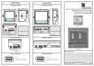
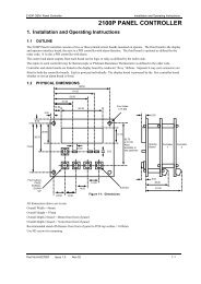
T820 HANDBOOK1.2 OTHER INFORMATION SOURCESFor details of Local Instrument Network (LIN) based Function Blocks, their parameters and input/output connectionsrefer to the LIN Blocks Reference Manual (Part no. HA082375U003) which explains how control strategy functionblocks are selected and interconnected etc. The creation, monitoring and Online Reconfiguration of LIN Databasesand LIN Sequential Function Charts (SFCs) is described in the LINtools Help (Part no. RM263001U055). TheELIN User Guide (Part no. HA082429) gives full details of installation, and how to configure an ELIN network,including setting the IP address using the instruments internal configurator. Modbus communications, including thethe interface type, can be configured, using the Modbus Tools software, see Modbus Tools OnLine Help(Part no. HA028988).Any specifically required T820 PageSets, which includes individual Pages for each required screen, can be designedand generated using the User Screen Editor software. All appropriate information is available in the User ScreenEditor Help (Part no. HA260749U005).Defined areas of the T820 can also be restricted by allocating the required access to the appropriate Users via SecurityManager. All appropriate information is available in the Security Manager Help (Part no. RM028131).Note. If you do not possess any document stated, please contact your distributor.1.3 THE T820The unit comprises the monochrome (black and white) graphical 128 x 64 pixel LCD screen, and 25 buttons, includingcursor, and navigation, numeric and user-definable keys.128x64 PixelLCD ScreenUser-DefinableKeysCursor and NavigationKeysMenu KeyOperatorKeysOption KeyCancel KeyNumeric/AlphanumericKeysCycle KeyFigure 1.3 T820 Human Machine InterfaceChapter 1Page 1 - 2HA029131Issue 3 Feb 08
T820 HANDBOOK1.3.1Main featuresThe main features of the T820 are as follows:LINThe Local Instrument Network (LIN) is a collection of LIN instruments, and LIN communications, etc. that togetherform the control system.LIN COMMUNICATIONThe Local Instrument Network (LIN) communications is our proprietry communications system used to connect eachLIN instrument in the network.ELIN COMMUNICATIONELIN communication is the LIN communications system transported via Ethernet. It allows peer-to-peercommunications between T820’s and the wider network via a standard Ethernet infrastructure, see Connections andWiring section.REDUNDANT POWER SUPPLY CONNECTIONThis instrument is capable of supporting a Redundant Power Supply Connection, disabled (default). Remove the wirelink to enable Redundant Power Supply Connection.It supports data in SRAM and the Real-Time Clock for approximately 1.5 years discontinuous use with an internalbattery.CONFIGURATIONContinuous strategies and Sequences are configured/downloaded/monitored with LINtools, the recommended LINconfiguration tool.ST USER ALGORITHMSSpecial ACTION function blocks support user algorithms written in Structured Text (ST) and are well-suited toimplement plant logical devices.SEQUENTIAL FUNCTION CHART (SFC)The Sequential Function Chart (SFC) is the graphical way LINtools (the recommended Configuration tool) representsa LIN Sequence (.sfc). A Sequence is employed when the process being controlled by the LIN Database (.dbf) canadopt several distinct states - e.g. ‘Starting Up’, ‘Full Running’, ‘Shutting Down’, etc. A LIN Sequence is aprogram that runs in a LIN instrument, in conjunction with a LIN Database. It interacts with its associated LINDatabase by writing new values to specified LIN Database fields, in response to changes in the values of otherspecified LIN Database fields.BLOCK SUPPORTMost standard LIN function blocks are supported. Special diagnostic blocks are available for hardware and softwarestatus reporting, refer to Diagnostics blocks section for a list of typically required diagnostic blocks, and the LINBlocks Reference Manual (Part no. HA082375U003) for a full description of each individual function block.DATA MANAGEMENTAutomatic data recording and archiving, providing Data Recording files, .uhh, to store recorded values from definedparameters selected from the database in the instrument. The .uhh files can be automatically archived to defined FTPServers, and then displayed as a charts using Review.HA029131Issue 3 Feb 08Chapter 1Page 1 - 3
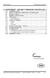
T820 HANDBOOK1.3.2 FEATURES (Cont.)EVENT LOGGINGAutomatic event logging, providing an ASCII text file to record and store individually time stamped events generatedin the instrument, and provide a means of indicating the impact of an event on the system.MODBUS COMMUNICATIONSModbus communication supported via both Serial and TCP interface types, see Installation section.Note. Always use the Modbus Tools software to configure the T820 Modbus parameters, see Modbus ToolsHelp (Part no. HA028988).MODBUS GATEWAY FACILITYThe Modbus Gateway facility provides a Modbus interface to the LIN Database. By using the techniques of LINfunction block caching, the Modbus Gateway facility can access data in other nodes distributed on the LIN, as well asLIN function blocks in the local LIN Database.It can support more than one Modbus Gateway facility and is configured by the GW_CON block. Each ModbusGateway facility is defined in one GW_CON block, e.g. it may require 3 GW_CON function blocks, one for eachModbus Gateway facility.This instrument can be configured to operate in Modbus Master mode. It can read and write values, to and from athird party (Modbus communicating) device operating in Modbus Slave mode. It can support more than one ModbusGateway facility which is configured using the GW_CON block, i.e. communications with more than one third partydevice configured to operate in Modbus Slave mode is permitted. Each Modbus Gateway facility is defined in oneGW_CON block, e.g. it may require 3 GW_CON function blocks, one for each Modbus Gateway facility (instrument).However, when this instrument is operating as a Modbus Slave, it only allows a PLC or supervisory system configuredas a Modbus Master to access values in the LIN Database.Note. For details concerning the Modbus communications protocol and interface types, see theCommunications Manual (Part no. HA028014).TRANSPARENT MODBUS ACCESS (TMA OR TALKTHRU).Transparent Modbus Access (TMA), otherwise known as TalkThru. This facility enables the iTools software package, seeiTools User Manual (Part no. HA026179) or other third party Supervisory Control And Data Acquisition (SCADA) softwareto inspect and edit specific I/O subsystem parameters while connected to an instrument configured to operate in ModbusMaster mode. Talking-through a Modbus Master to access the I/O subsystem parameters can be slower than if actuallyconnected directly because the Modbus Master is interleaving the iTools messages with its own data.Note. Specific function codes have been allocated to enable the TalkThru facility.SCADAsoftwareEthernet networkModbus-M(Master) withTalkThruconfiguredNote. The graphic shows ModbusSerial, but Modbus-TCPmay be supported via theEthernet port.Modbus-S(Slave)Modbus-S (Serial)Modbus-S(Slave)Modbus-S(Slave)Figure 1.3.2 Example of Transparent Modbus Access (TMA or TalkThru) configurationChapter 1Page 1 - 4HA029131Issue 3 Feb 08
T820 HANDBOOKCHAPTER 2 INSTALLATIONThis chapter is intended for use by those responsible for the installation and commissioning of the T820 and consistsof the following sections:• Safety and Electro-Magnetic Compatibility (EMC) information (section 2.1)• Unpacking (section 2.2)• Mechanical layout and installation (section 2.3)• Setting the communication options (section 2.4)• Connections and wiring (section 2.5)2.1 SAFETY AND ELECTRO-MAGNETIC COMPATIBILITY (EMC) INFORMATIONPlease read this section before installing the T820.The T820 is designed to meet the requirements of the European Directives on Safety and Electro-MagneticCompatibility (EMC). It is, however, the responsibility of the installer to ensure the safety and EMC compliance ofany particular installation.2.1.1Installation requirements for EMCThe T820 conforms with the essential protection requirements of the EMC Directive 89/336/EEC, amended by93/68/EEC. It also satisfies the emissions and immunity standards for industrial environments.To ensure compliance with the European EMC directive, BSEN61326, certain installation precautions are necessaryas follows:• General guidance. For general guidance refer to the EMC Installation Guide (Part no. HA025464).• Routing of wires. To minimise the pick-up of electrical noise, low voltage DC connections and sensor inputwiring should be routed away from high-current power cables. Where it is impractical to do this, shielded cablesshould be used, with the shield grounded at both ends.• Communications wires. If the communications wires cover a distance greater than 30metres or leave the buildingmake sure they are screened and connected to the connector shell at one or both ends to ensure immunity to surgeevents.It is recommended that...the Instrument Chassis is earthed to provide the best Electro-Magnetic Compatibility (EMC)performance.HA029131Issue 3 Feb 08Chapter 2Page 2 - 1
T820 HANDBOOK2.1.2Installation safety requirementsCautionIn order to comply with the requirements of BS EN61010, the voltage applied across terminals may not exceed thoseterminals’ isolation voltage. For terminals specified as having no isolation, the maximum permissible voltage is30V ac or 50 V dc.PERSONNELInstallation must ONLY be carried out by qualified personnel.POWER ISOLATIONThe installation must include a power isolating switch or circuit breaker. This device should be in close proximity(1 meter) to the controller, within easy reach of the operator and marked as the disconnecting device for theinstrument.CONDUCTIVE POLLUTIONElectrically conductive pollution (e.g. carbon dust, water condensation) must be excluded from the cabinet in whichthe controller is mounted. To secure a suitable atmosphere in conditions of conductive pollution, fit an air filter to theair intake of the cabinet. Where condensation is likely, include a thermostatically controlled heater in the cabinet.VENTILATIONEnsure that the enclosure or cabinet housing the unit provides adequate ventilation/heating to maintain the operatingtemperature of the instrument.PRECAUTIONS AGAINST ELECTROSTATIC DISCHARGECautionCircuit boards inside the unit contain components which can be damaged by static electrical discharge. Before anycircuit board is removed or handled, all electrostatic precautions must be observed, by ensuring that the handler, theinstrument and the circuit board are all at the same potential.2.1.3Keeping the product safeTo maintain the unit in a safe condition, observe the following instructions.MISUSE OF EQUIPMENTIf the equipment is used in a manner not specified in this handbook or by the distributor, the protection provided by theequipment may be impaired.SERVICE AND REPAIRSExcept for those parts detailed in the Service section, this unit has no user-serviceable parts. Contact the nearestmanufacturer’s agent for repair.Chapter 2Page 2 - 2HA029131Issue 3 Feb 08
T820 HANDBOOK2.2 UNPACKINGThe unit and accessories should be carefully unpacked and inspected for damage. The original packing materialsshould be retained in case re-shipment is required. If there is evidence of shipping damage, the supplier or the carriershould be notified within 72 hours and the packaging retained for inspection by the manufacturer’s and/or carrier’srepresentative.2.2.1Handling precautionsCautionCircuit boards inside the unit contain components which can be damaged by static electrical discharge. Before anycircuit board is removed or handled, all electrostatic precautions must be observed, by ensuring that the handler, theinstrument and the circuit board are all at the same potential.2.2.2Package contentsThe unit may form part of a larger assembly, and/or may be housed in a floor or wall-mounted enclosure. If so, thedocumentation that accompanied those items should be referred to.The package contents should be checked against the order codes, using the labels on the components.PRODUCT LABELLINGProduct labelling includes:• Sleeve label. On the back of the unit, showing all appropriate build information.• Compact Flash Memory Card label showing firmware version, issue number, initial software licence andEthernet-Mac Address.• Safety earth symbol adjacent to safety earth stud.SYMBOLS USED IN THE LABELLINGOne or more of the symbols in the table below, may appear on the labelling of the unit:Label!FunctionCaution, refer to the accompanying documentsFunctional (Ground/Safety) earthProtective earth terminalRisk of electric shock40 Year Environmently Friendly Usage PeriodHA029131Issue 3 Feb 08Chapter 2Page 2 - 3
T820 HANDBOOK2.3 MECHANICAL LAYOUT AND INSTALLATIONFigure 2.3 shows the T820 with the cover fitted and removed for clarity.DIN railLocking MechanismDIN railMounting BracketCompact FlashMemory CardCOM110/100+RedundantCOM110/100See Note+ + - -24V+ + - - 24VTERMUNTERM5W3WLK1 LK2LK2LK1Power Supplywire linkSafetyEarth StudRear CoverScrew(1 per corner)InternalBatteryRS485ConnectorEthernetConnector+ + - -24V dc supplyNote. Set RS485 Link positions (LK1 and LK2) and, if required, remove the wire link to enable a RedundantPower Supply before installing.Figure 2.3T820 - Rear ViewChapter 2Page 2 - 4HA029131Issue 3 Feb 08
T820 HANDBOOK2.3.1Mount a T820The T820 can be DIN rail or panel mounted.DIN RAIL MOUNTINGNote. Remember to set RS485 Link positions (LK1 and LK2), and if required, remove the wire link to enablethe connection of a Redundant Power Supply before installing, see Figure 2.3 parts reference.For DIN rail mounting, use symmetrical DIN rail to EN50022-35 X 7.5 or 35 X 15 mounted horizontally.1. Mount the DIN rail, using suitable bolts.2. Ensure that the DIN rail makes good electrical contact with the metal base of the enclosure.3. Guide the T820 to the DIN rail, allowing the lower teeth of the DIN rail Mounting Bracket to rest behind the DINrail itself.4. Slowly and firmly, push the top of the T820 back until the DIN rail Locking Mechanism springs back into place.This is confirmed by an audible ‘Click’. The T820 is now mounted to the DIN rail.Note. When DIN rail mounted, the unit is rated IP20.DIN railLocking Mechanism4DIN railMounting Bracket4ClickDIN railDIN rail3Rear CoverFigure 2.3.1Mounting T820 to a DIN railHA029131Issue 3 Feb 08Chapter 2Page 2 - 5
T820 HANDBOOK2.3.1 Mount a T820 (Cont.)DIRECT PANEL MOUNTINGNote. Remember to set RS485 Link positions (LK1 and LK2), and if required, remove the wire link to enablethe connection of a Redundant Power Supply before installing, see Figure 2.3 parts reference.1. Check that the mounting panel is no thicker than 25mm (typically for wood or plastic) and no thinner than 2mm(for steel).2. In the mounting panel, cut an aperture 99mm x 138mm (+ 1mm). If more than one T820 is to be mounted in thepanel, the recommended minimum spacings are as shown below.3. From the front side of the mounting panel, insert the instrument (rear end first) through the aperture.4. Support the rear of the T820 so that the seal is flat against the front of the mounting panel.5. Insert two panel clamps into the opposing pair of rectangular apertures at the sides of the case.6. Tighten the screws of the clamps sufficiently to hold the T820 firmly in position.Note. When mounted directly in a panel the unit is rated IP66 front of panel, and IP20, rear of panel.X*Panel cutout99mm x 138mm(+ 1mm)Top View99mmY*104mm6mm43mmRear cover fixing screws(4, 1 per corner)Front View144mm68mm115mm138mmMaximum panel thickness= 22mmView on right-hand sideCase clampingMinimum recommended inter-unit spacingClamp Position X* Y*Left and right 14 mm 7.5 mmFigure 2.3.1Mounting the T820 to a PanelChapter 2Page 2 - 6HA029131Issue 3 Feb 08
T820 HANDBOOK2.4 SETTING THE COMMUNICATION OPTIONSThe RS485 communication options are configured using the 2 banks of 6 pin Links, LK1 and LK2, located within theT820. These links will configure either,• 3-wire or 5-wire RS485 communications, using LK1• Terminated or Unterminated, using LK2Note. Remember to set RS485 Link positions (LK1 and LK2), and if required, remove the wire link to enablethe connection of a Redundant Power Supply before installing, see Figure 2.3 parts reference.2.4.1Link LocationThe links, LK1 and LK2, located within the T820, for setting communication options are only accessible (Figure 2.3)when the Rear Cover is removed.2.4.2Link Functions5-WIRE/3-WIRE SELECTION (LK1)The first bank of 6 pin Links, LK1, specify that RS485 3-wire/5-wire Modbus communications is required.Link Position FunctionLK1 3-5 and 4-6 RS485 3-wire communications.LK1 1-3 and 2-4 RS485 5-wire communications.TERMUNTERM5W3WLK1 LK212Note. Remember when this instrument is operating asa Display unit, LK1 pins 1-3 and 2-4 must beconfigured.10/100+ + - -24V56Note. Pin numbers shown for clarity.TERMINATED/UNTERMINATED SELECTION (LK2)The second bank of 6 pin Links, LK2, indicates that the RS485 link is internally terminated or unterminated.Link Position FunctionTERMUNTERM5W3WLK1 LK215LK2 3-5 and 4-6 Unterminated RS485 communications.LK2 1-3 and 2-4 Terminated RS485 communications.2610/100Note. Pin numbers shown for clarity.+ + - -24VHA029131Issue 3 Feb 08Chapter 2Page 2 - 7
T820 HANDBOOK2.5 CONNECTIONS AND WIRINGIf assembling the system yourself, refer to the LIN/ALIN Installation & User Guide (Part no. HA082429U005), theELIN User Guide (Part no. HA082429) for advice on LIN connections and wiring and the Communications Manual(Part no. HA028014) for advice on Modbus connections and wiring.Figure 2.5a and Figure 2.5b below, show a simplified overall connection diagram for an RS485 Serial or an Ethernetcontrol system using an Ethernet hub/switch.Category 5 cables may be used for individual line lengths of up to 100 metres. For line lengths greater than this, oneor more pairs of hubs with fibre-optic connections is recommended.T820I/O SubsystemTo/From ProcessFigure 2.5a Typical RS485 Serial connection diagramT820Network Switch(Rapid SpanningTree Protocol(RSTP))PC -Duplex connection(operating Configuration Tools)PC -Duplex connection(operating Configuration Tools)Network Switch(Rapid SpanningTree Protocol(RSTP))I/O SubsystemTo/From ProcessI/O SubsystemI/O Subsystems -Ethernet connectionsTo/From ProcessI/O SubsystemTo/From ProcessFigure 2.5b Typical Ethernet connection diagramChapter 2Page 2 - 8HA029131Issue 3 Feb 08
T820 HANDBOOK2.5.1CommunicationsETHERNET (100/10 BASE-T) CONNECTORNote. Ethernet communications are only available on Controller units.The Ethernet RJ45 connector includes 2 LEDs, a Yellow showing communication activity and a Green LED showingspeed (On shows 100Mbps communication speed, Off shows 10Mbps communication speed).Figure 2.5.1a shows the RS485 Ethernet RJ45 pinout connections.PinSignalEthernetPin 8Pin 1Ethernet RJ45 plug: View on underside8 Not Used7 Not Used6 RX-5 Not Used4 Not Used3 RX+2 TX-1 TX+Plug shroud to Cable screenNote. Modbus-TCP Communications will be supported using these pinouts.Figure 2.5.1a Pinouts for T820 Ethernet RJ45 type plugsRS485 SERIAL CONNECTORThe RS485 Serial RJ45 connector includes 2 LEDs, a Yellow showing communication activity and a Green LED thatis not used.The RS485 Serial RJ45 connector may be used to communicate with a T2550, or to connect to a Modbus network forcommunicating with a variety of third-party serial devices.Figure 2.5.1b shows the connector pinouts for Serial communications. These must be configured in conjunction withthe Links, LK1 and LK2.Note. The T820 Display variant supports the 5-wire pinout only. This allows direct connection to a T2550.Pin 8Pin 1RS485 RJ45 plug: View on undersideEIA485 SerialPin 3-wire 5-wire8 N/A TX+ (TxA)7 N/A TX- (TxB)6 Gnd Gnd5 N/A N/A4 N/A N/A3 Gnd Gnd2 A RX+ (RxA)1 B RX- (RxB)Plug shroud to Cable screenFigure 2.5.1b Pinouts for T820 RS485 Serial RJ45 type plugsHA029131Issue 3 Feb 08Chapter 2Page 2 - 9
T820 HANDBOOK2.5.2Electrical InstallationNote. Before carrying out any wiring, please read the Safety and EMC Information.WarningVoltages of greater than 40V (peak), relative to the safety earth potential, must never be applied to any of the dc inputterminals (positive or negative), as under such circumstances, the unit may become hazardous to the touch.It is recommended that external 2 Amp fuses are fitted in each positive supply line.CautionAlways ensure the power is isolated prior to removing the rear cover and before configuring the hardware.A Polycarbonmonofluoride Lithium battery is also fitted in the unit. When fully charged this will maintain the SRAMand Real-Time Clock (RTC) data for approximately 1.5 years discontinuous use.POWER RING CONNECTIONThe unit can be connected as part of a Power Ring to a maximum of 16A.1. Connect the input supply to the + and - terminals,ensuring the correct polarity.2. Connect the output from the remaining + and -terminals.REDUNDANT POWER CONNECTIONRedundant Power can be supplied via two independant sources.Note. Remove the Redundant Power Supplywire link, Figure 2.3, to enableRedundant Power Supply facility.10/100TERMUNTERM5W3WLK1 LK2+ + - -24VRedundant PowerSupply wire link1. Connect the first input supply to the + and -terminals. Ensure the correct polarity.2. Connect the second input supply to the + and- terminals. Ensure the correct polarity.Input Supply+-+ -Second Input supply oroutput to next instrumentFigure 2.5.2Power Supply connections2.5.3Safety earth connectionAs shown in Figure 2.3, an earth stud connection is provided. This stud should be bonded to a good local earth usingmultistrand tri-rated 1.5mm 2 (21A) green/yellow earth cable, with ring terminals for security.Chapter 2Page 2 - 10HA029131Issue 3 Feb 08
T820 HANDBOOKCHAPTER 3 GETTING STARTEDThis chapter is for all prospective users of the instrument, including those responsible for installing and commissioningit. The chapter consists of the following sections,• Switch-on, and the opening display, including the navigation keys (section 3.1)• The Screen: Built-in pages and entry (section 3.2)• The Pop-up menu (section 3.3)• The Alarm page (section 3.4)• The Access page (section 3.5)3.1 SWITCH-ON AND THE OPENING DISPLAYThis section shows the instrument factory set defaults.3.1.1Switch onThe unit is not fitted with a power switch, so the switch-on arrangements depend upon the particular installation.Approximately 15 seconds, after switch-on an opening display appears that fills most or all of the screen area.If this opening display fails to appear, check,• the power supply• with the Commissioning Engineer that the instrument powered up faultlessly when finally installed andcommissioned.After this, if the problem is still unresolved, recall the Commissioning Engineer.3.1.2The user interfaceThe user interface is open to customisation, either before operation or with the instrument taken out of service. Forexample the opening page (or the Home page) can differ, other pages can be changed, and User pages (User screensgenerated using the User Screen Editor (Part no. HA260749U005)) can be added. The size of the User generatedpages can differ, and legends can also differ.Note. All built-in menus and pages supplied by the manufacturer have a pre-defined reference number, seeCustomising section. Built-in menus and pages can be displayed from User generated Pages byspecifying the relevant reference number as a Structured Text (ST) action.The Operation and Management chapters of this manual describe the system of menus and pages, Built-in pages,supplied by the manufacturer, before any customisation by the user.HA029131Issue 3 Feb 08Chapter 3Page 3 - 1
T820 HANDBOOK3.1.3The standard interfaceThe Standard Interface consists of a ‘Screen’ and a group of ‘Navigation and Menu’ keys.128x64 PixelLCD ScreenCursor and NavigationKeysMenu KeyOperatorKeysOption KeyCancel KeyCycle KeySCREENFigure 3.1.3 The Screen, and Navigation and Operator keysThe Screen is used to display defined system values via User generated Pages created using the User Screen Editor(Part no. HA260749U005). It will also allow the User to select specific Menus for displaying the requiredinstrument-specific and application-specific functions from a selection of Built-in pages, i.e. showing active andinactive alarms, and enabling a specific level of security.NAVIGATION AND MENU KEYSThe Navigation and Menu keys carry out the following functions:UPDOWNLEFTRIGHTRETURNMENUOPTIONCANCELCYCLEHighlights an option one level above the currently selected item, moving vertically in a menustructure.Highlights an option one level below the currently selected item, moving vertically in a menustructure.Highlights an option one position to the left of the currently selected item. Also moves forward(left) between successive pages of tabular data. Action depends upon context.Highlights an option one position to the right of the currently selected item. Also moves back(right) between successive pages of tabular data. Action depends upon context.Confirms the selection or configuration entry. Action depends upon context.Displays the Menu (top-level) screen, showing the ACCESS, SYSTEM, and ALARMS pages.Displays a menu, or an extra set of keys, for options specific to the page on display.Closes the currently displayed Menu screenDisplays the next page in the sequence to be scrolled through, e.g. the System Summary pagehas two pages, the other is displayed when this key is used.Chapter 3Page 3 - 2HA029131Issue 3 Feb 08
T820 HANDBOOK3.1.4The opening displayNote. If the system has been customised and configured with an overview screen, the opening page shows theUser selected overview screen.The opening display is the System Summary page depicted in Figure 3.1.4, below.System SummaryInstrument type: T820Serial no: 197Firmware: 1.1*Node: 01Note. The Node number is configured as a Hex number. The ‘A’, ‘B’ or ‘C’ alphanumeric value is input bypressing the ‘2’ numeric key the appropriate number of times, whereas the ‘D’, ‘E’, or ‘F’alphanumeric value is input by pressing the ‘3’ numeric key the appropriate number of times.Figure 3.1.4 System Summary pageThe System Summary page confirms the order options that were specified for this instrument. Operation of the‘Down’ or ‘Cycle Screens’ key calls a second page displaying any additional software options that are fitted.Initially the opening display is ‘Locked’. In this state, only the Navigation and Menu keys are active. Operation of theMENU key causes the opening ‘Pop-up’ menu of the Standard Interface to appear. Selecting the ACCESS optioncalls the Security Access page, see The Access Page section. This allows the current Security Access level of theinstrument to be changed using an appropriate password.HA029131Issue 3 Feb 08Chapter 3Page 3 - 3
T820 HANDBOOK3.2 THE SCREENThe Screen is used to display system values via Pages created using the User Screen Editor(Part no. HA260749U005). It will also allow the User to select a Menu for displaying the requiredinstrument-specific, application-specific and program-specific functions, i.e. displaying active and inactive alarms,configuring a specific level of security, and controlling the application.Note. System specific information will appear only if correctly configured Pages are generated using theUser Screen Editor (Part no. HA260749U005 ).Screen3.2.1Built-in pagesFigure 3.2 The ScreenThe Built-in pages are a menu system whose structure is hierarchical like a family tree. At the top is the Pop-up menuwhich offers a choice of submenus as depicted below.Security AccessACCESSSYSTEMALARMSFigure 3.2.1 The Buitl-in page: top level menuNote. ACCESS, SYSTEM and ALARMS appear on every instrument, additional Options can appear only ifconfigured using the User Screen Editor(Part no. HA260749U005).Below this menu level, there are further levels of functions that give users successively more detailed control ofdifferent aspects of programs, applications, and the instrument itself.3.2.2Built-in page entryInformation entry is via the Navigation keys to select an area on the screen and confirm the selection by using theReturn key.Chapter 3Page 3 - 4HA029131Issue 3 Feb 08
T820 HANDBOOK3.3 THE POP-UP MENUNote. In the following description of the Pop-up menu, and indeed of all the screen displays throughout thismanual, it is important to note that almost everything is open to customisation. On any particularinstrument the legends can be different from those shown here, or need not exist at all.Throughout this manual what is called the Standard Interface is described. This is generated by themanufacturer, before any customisation by the user. The Minimum Interface, is generated by theminimum configuration necessary for the instrument to function.The Standard Interface, or Built-in pages, Pop-up menu consists of three options: ACCESS, SYSTEM and ALARMS,see Figure 3.2.1. With the display ‘Locked’, i.e. before a password is entered and access to the configuration menus isrestricted, only ACCESS and SYSTEM are active. However, most users will operate the Standard Interface withadditional User Screens generated using the User Screen Editor, see User Screen Editor Online help(Part no. HA260749U005).In this case, with the display locked, ACCESS, SYSTEM, and HOME/USER SCREENS will be active.From this menu, without a password, you can explore the menu systems and display information. The SYSTEM, andUSER SCREENS displays are view-only at this locked stage; only ACCESS will respond fully to menu and keyselections, to grant access, see the Gaining Access section.The functions of each page:ACCESSSYSTEMALARMSHOME/USER SCREENSWith a valid password, this page is the gateway to the functions-sets below that areneeded to do the job.is the gateway to the system functions of the instrument (that is, the instrument-specificand application-specific functions, as opposed to the program-specific functions).is the gateway to the alarm functions.If configured, this returns you to the Home page. The Home page may be a single page,or it may be the root page of a user-written hierarchy of pages. If HOME/USERSCREENS is not configured, the System Summary page acts as a default Home page,displayed after a timeout.Note. All built-in pages supplied by the manufacturer have a pre-defined reference number, see Customisingsection. Built-in pages can be displayed from User generated Pages by specifying the relevantreference number as a Structured Text (ST) action.Of the two or three further levels in the hierarchy, all are available to Engineers, but only some are available toOperators and Commissioning Engineers. This helps to improve usability, by hiding those facilities which are notcurrently required.HA029131Issue 3 Feb 08Chapter 3Page 3 - 5
T820 HANDBOOK3.4 THE ALARM PAGEThe Alarm Page is used to display any alarm signals (triggered by abnormal conditions detected in the process undercontrol), instrument alarms etc.Plant MimicACCESSSYSTEMALARMSPlant MimicT2550_C2ACKHISTORYSUMMARYFigure 3.4 The Alarm PageAlarms can be set to be latching or non-latching (auto acknowledging). Latching alarms are annunciated untilacknowledged; auto-acknowledge alarms are annunciated until the alarm trigger returns to a non-alarm state.Decisions on which conditions should trigger an Auto-Ack Alarm rather than an Acknowledge Alarm (latching alarm)are made during configuration.3.4.1Alarm state indicationAlarm state is active or inactive, acknowledged or not. An alarm is triggered (becomes active) when the value it ismonitoring moves outside a pre-set value or range of values. It becomes inactive when the signal returns to within thepreset value or range of values. These values are set up during configuration.To acknowledge an alarm, select the alarm using the Navigation keys and confirm the selection using the Return key.Again using the Navigation and Return keys, select Alarm Summary. This will display a list of all current alarms.Use the Navigation keys to select the Alarm and by pressing the Option key display the types of alarms that requireacknowledging. Select the Alarm type and Acknowledge using the Return key. (Access permission needs to be set.)Note. If an alarm is selected, pressing the Right arrow displays additional alarm information, e.g. ACTIVE,when the alarm was set, CLEAR, when the alarm cleared, and ACK, when the alarm wasacknowledged. Pressing again hides this additional information.In the Alarm Summary page, seeFigure. 3.4.1, Alarm indicators flash until the alarm has been acknowledged, at which time theybecome illuminated steadily.In order to gain more details, the Alarm History page can be displayed, see Alarm History section.Alarm SummaryMod16_C2 HardwarMod16_C1 HardwarMod16_C2 HardwarAlarm SummaryMod16_C2 HardwarACTIVE: 03/01 20:09CLEAR:ACK: ----- -----Figure 3.4.1 The Alarm Summary PageChapter 3Page 3 - 6HA029131Issue 3 Feb 08
T820 HANDBOOK3.4.2Responding to alarmsThere are four possible responses to an alarm,• do nothing• get more information, by bringing up the Alarm History page, which is a list of past and current alarms and events• acknowledge the alarm, using the Menu, Navigation, Option and Return keys.• report and then remedy the abnormal conditionDO NOTHINGDoing nothing is acceptable when a non-serious abnormal condition did exist but it has now returned to normal, andthat it has been acknowledged.Doing nothing is also acceptable with an Alarm that is not the result of its having been manually acknowledged. In thiscase, the alarm will have been triggered by an Auto-Ack alarm, which does not require active intervention but will giveinformation about a slightly abnormal condition.ALARM HISTORY PAGEFigure 3.4.2a shows the Alarm History page of the instrument.The Alarm History page displays a list of alarm conditions and Events. By pressing the Right arrow, additional alarminformation showing when they occurred, and if appropriate, when they were cleared or acknowledged. Events andother items which are not clearable or which cannot be acknowledged display ----- ----- in the CLEAR and ACK fields.The Alarm History record starts in the first instance from when the instrument is powered up for the first time.Thereafter it is preserved through any automatic restarts called hot starts, see Setting the Start-up strategy section.Note. Each existing record is lost and a new one started whenever a new application database is loaded.The Standard model of the instrument can retain and display a total of 512 alarms or Events. Once these limits areexceeded the oldest item in each case is deleted when a new addition is made to the list.Alarm HistoryMod16_C2 HardwarMod16_C1 HardwarMod16_C2 HardwarAlarm HistoryMod16_C2 HardwarACTIVE: 03/01 20:09CLEAR:ACK: ----- -----Figure 3.4.2a The Alarm History PageHA029131Issue 3 Feb 08Chapter 3Page 3 - 7
T820 HANDBOOK3.4.2 Responding to alarms (Cont.)ALARM ACKNOWLEDGEMENTUnacknowledged alarms are made evident by the flashing of the alarm bell icon in the Alarm History page and theAlarm Summary page.Alarm HistoryMod16_C2 HardwarMod16_C1 HardwarMod16_C2 HardwarActive Alarms(Alarm bell icon)Figure 3.4.2b Alarm IndicationIMPORTANT It is recommended that an alarm is acknowledged before any attempt is made to rectify thecause of the alarm.To acknowledge an alarm, select the alarm using the Navigation keys and Acknowledge this selecting the ACK optionand confirm using the Return key.Note. If an alarm is selected, pressing the Right arrow displays additional alarm information, e.g. ACTIVE,when the alarm was set, CLEAR, when the alarm cleared, and ACK, when the alarm wasacknowledged. Pressing again hides this additional information.MULTI-LINE DISPLAYOperation of the Right arrow key toggles between single-line and multi-line working. Single line working is asdescribed above, and as shown in Figure 3.4.2a. When in two-line working, each alarm has a second line showing theUser ID of the user who was logged on at the time of the alarm, or event.Chapter 3Page 3 - 8HA029131Issue 3 Feb 08
T820 HANDBOOK3.5 THE ACCESS PAGEThis area is displayed to allow a different level of security access to the T820. Each security access level can bepassword restricted to ensure the security of the T820. Selecting this option from the Built-in pages calls the first ofthe Access pages described in Gaining Access section.3.5.1Gaining accessThe Unit is supplied with the standard access system in operation and is configured with the following types of Users,• Locked (Disabled User)• Operator• Commission (Commissioning Engineers)• EngineerEach of these User types has what is known as a level of access to the facilities of the instrument, based upon the needsof the job, and they gain access to that level by typing in a password. The level of access is fixed for each type of User.That is to say, all Operators share the same password to their level of access; all Commissioning Engineers share thesame password to their level of access; and all Engineers share the same password to their level of access. TheEngineer-level password gives access to every facility in the instrument.Note: Only from Engineer-level can passwords be changed.The hierarchy of levels is LOCKED (lowest), OPERATOR (next lowest), COMMISSION (middle), ENGINEER(highest). You need a password to change up levels, but not to change down. No password is needed for Locked.What follows are step-by-step instructions on how to navigate the menu system to get access to your level of facilities.The assumption is that you have your password ready. Passwords are set and re-set by the Engineer.Note: For first-time access, immediately after commissioning, see the Controlling Access section.To gain access to a required level of functions,1. With the Unit powered up, press the Menu key.The top level menu of the Built-in pages (figure 3.2.1)appears.2. Select the ACCESS option and confirm using theReturn key.The Security Access page appears.Plant MimicACCESSSYSTEMALARMS3. Select the ‘New Level’ field, and again confirmselection using the Return key.The Security Access pick-list appears.Security AccessCurrently: OPERATORNew Level: OPERATORPassword: ********[CHANGE]HA029131Issue 3 Feb 08Chapter 3Page 3 - 9
T820 HANDBOOK3.5.1 Gaining access (Cont.)4. Using the Navigation keys select the required level ofaccess,• LOCKED• OPERATOR• COMMISSION• ENGINEERConfirm using the Return key.The pick-list disappears, revealing the Security Accesspage again, showing the selected level (LOCKED,OPERATOR, COMMISSION or ENGINEER) in the‘New Level’ field.Security AccessLOCKEDOPERATORCOMMISSIONENGINEER5. Select the Password field (shown as asterisks) using theNavigation keys and confirm using the Return key.The asterisks are removed and Password field starts toflash.Note. A Password is not required when selectinga lower security access level, e.g.ENGINEER to OPERATOR.Security AccessCurrently: OPERATORNew Level: OPERATORPassword: ********[CHANGE]6. Enter each character/numeric of the required Password,using the alphanumeric keys. Each key press selects thenext alphanumeric in the list. The selectedalphanumeric is only entered in the password when thealphanumeric list disappears.G1 2 BC4 HIAJ5 KLDM3 EFN6ONote. A Password is entered following the sameprinciples as the mobile phone, usingmultiple keys presses to select the letter ornumber required.Erroneous characters can be deleted by selecting therelevant character and pressing the appropriatealphanumeric key.U7 8PQRST. 0VWXYZ±Security Access9Currently: OPERATORNew Level:WXYZ9OPERATORPassword: *_[CHANGE]Chapter 3Page 3 - 10HA029131Issue 3 Feb 08
T820 HANDBOOK3.5.1 Gaining access (Cont.)7. Select the ‘Change’ field using the Navigation arrowsand confirm using the Return key.Security AccessCurrently: OPERATORNew Level: ENGINEERPassword: ********[CHANGE] [PASSWDS]8. The display blanks momentarily, and returns showingthe selected level (OPERATOR, ENGINEER orCOMMISSION) in the ‘Currently’ field, as well as the‘New Level’ field.Note. If not, an incorrect password must have beenentered. Check that the password is correctfor the level selected in step 4, and thenrepeat from step 3 onward.Security AccessCurrently: ENGINEERNew Level: ENGINEERPassword: ********[CHANGE] [PASSWDS]The unit now permits the selected level of configuration.IMPORTANT To ensure the security of the unit, it MUST never be unattended while ENGINEER securityaccess has been selected.HA029131Issue 3 Feb 08Chapter 3Page 3 - 11
T820 HANDBOOKIntentionally left blankChapter 3Page 3 - 12HA029131Issue 3 Feb 08
T820 HANDBOOKCHAPTER 4 CONFIGURATIONThis chapter presents and describes the recommended Configuration Tools and issues concerning the instrumentcommunication protocol.Note. Configuration and Ethernet functionality is only applicable to a Control unit. A Display unit will onlyshow the LIN Database of the connected T2550 I/O Subsystem.The main topics of this chapter are:• Tools: The Automatic Build and Configuration Tools (section 4.1)• Automatic Build (section 4.2)• LINtools (section 4.3)• Modbus Configuration Editor (section 4.4)• Instrument Properties Dialog (section 4.5)4.1 TOOLS: THE AUTOMATIC BUILD AND CONFIGURATION TOOLSMost LIN Database configuration of a Control unit will be done before despatch, using the LINtools configurationtool. However, at start-up a basic LIN Database and communications parameters can be automatically configured forthe T820 instrument using the Automatic Build procedure. A basic Terminal Configurator, see Terminal Configuratorsection, is also resident within the Control unit. The instrument employs the standard LIN block structured approach.Using the recommended LINtools program also allows the creation of new LIN Databases, including new functionblocks, and the editing of existing configurations on-site and on-line, usually to accompany modifications to theprocessing plant. The LINtools Help (Part no. RM263001U055) should be referred to for details of the reconfigurationprocedures using the LINtools program.Note. Refer to LIN Blocks Reference Manual (Part no. HA082375U003) for full details of the function blocksavailable for control strategies, and how to configure their parametersHA029131Issue 3 Feb 08Chapter 4Page 4 - 1
T820 HANDBOOK4.2 AUTOMATIC BUILDAn automatically generated LIN Database does not result in a complete, usable control strategy, and is dependant onthe hardware configuration of the Instrument. However, it does provide the user with sufficient information, forming agood starting point for the user to begin building a more detailed control strategy.An instrument operating as a Control unit, can automatically generate a basic range of diagnostic function blocks toassist in identifying and monitoring the instrument and system, generating and configuring appropriate function blocksto replicate the hardware.The table below shows a list of diagnostic function blocks that are automatically generated as part of the automaticallycreated LIN Database, if a LIN Database is not loaded and the power is isolated, then re-applied.Block Type Block Name FunctionDB_DIAG DDIAG_nn Database diagnostics block. Shows actual and maximum resource levels of the LINDatabase by the current software. Displayed parameter values are only valid at runtime.EDB_DIAG EDIAG_nn External database diagnostics block. Shows connection information to one externaldatabase running in remote instruments and monitors the cached block update rate tuningalgorithm.EIO_DIAG EIODI_nn Ethernet I/O system diagnostic block. Shows the current state (Healthy/Unhealthy) of theexpected and actual I/O modules at each site. It can display a maximum of 16 I/O sites onone screen.ELINDIAG ELIND_nn ELIN diagnostics block. Statistics on the operation of the Ethernet Local InstrumentNetwork (ELIN).IDENTITY IDENT_nn IDENTITY diagnostics block. Identifies the instrument containing this function block.LIN_DEXT LDEXT_nn LIN High-level diagnostics extension block. Statistics on the operation of the LocalInstrument Network (LIN).OPT_DIAG ODIAG_nn Options/Licence Control System diagnostics block. Shows the user system attributes thatmay impose some limit of operation, or cause a licence violation alarm. The block is notessential to the LIN Database, and can be added while online.PNL_DIAG PNLDI_nn Panel diagnostic block. Shows information about the panel.SFC_DIAG SFCDI_nn Sequence diagnostics block. If SFC is enabled, this block shows actual and maximumresource levels of the sequence by the current software. It displays parameter values thatare only valid at runtime.TACTTUNE TTUNE_nn Tactician tuning block. System task monitoring in priority order.USERTASK UTASK_nn User Task diagnostic block. Control strategy task performance monitoring.Note. ‘nn’ denotes the numeric instance of that specific block type.Table 4.2 Automatically generated diagnostic function blocksChapter 4Page 4 - 2HA029131Issue 3 Feb 08
T820 HANDBOOK4.2.1Preparing for the Automatic BuildBefore the Automatic Build process can be started, any active application must be stopped and unloaded. Only thenshould power be isolated and re-applied, initiating the automatic generation of a LIN Database ‘_auto.dbf’, andcorresponding ‘_auto.run’ file. A ‘*.run’ file is automatically generated each time a LIN Database is started, but isalways transparent to the user. The automatically generated LIN Database will run automatically, but is not saved tothe filesystem.Note. A Control unit requires that both Hot Start and Cold Start parameters are set OFF.Use the ‘Save as’ command at the instrument level of the ‘manufacturers Network Explorer’ or the ‘Save’ commandin the ‘Terminal Configurator’ to save an automatically generated LIN Database.Note. The only constraints on the name of the LIN Database is that it must be a unique 8-character string,although it is recommended that the name of the LIN Database is the Instrument Type and the LINAddress, i.e. T820_0f.Control UnitDisplay UnitHot/Cold Startparameters set Off(Startup Strategy menu)Power up unit(Database and.run files areautomatically created)Power upI/O subsystem after theControl Strategy hasbeen configured andthe Hot/Cold Startparameters setas required(Startup Strategy menu)Configure and savecontrol strategyDatabase RunsAutomatically. the unit andI/O subsystem communicate.Unit used to display valuesHot/Cold Startparameters setas required(Startup Strategy menu)Power down instrumentPower up instrumentLocal DatabaseRuns AutomaticallyFigure 4.2.1 Automatic LIN Database generation routineHA029131Issue 3 Feb 08Chapter 4Page 4 - 3
T820 HANDBOOK4.3 LINTOOLSThe LINtools program provides the user with a view of the control strategy components that compose theconfiguration of a single device, and an easy way to manage those components. There may be more than one of eachcomponent, but not always all component types.• I/O Modules LIN Database (file extension .dbf)• LIN Databases (Function Block Diagram - FBD, file extension .dbf)• Sequences (Sequential Function Chart - SFC, file extension .sdb)• User Screen PageSets (file extension .uxp and .ofl)• Action block methods (Structured Text - ST, and Ladder, file extension .stx and .sto)• Modbus Gateway configurations (file extension .ujg and .gwf)In summary, LINtools• Provides a comprehensive view of the instrument configuration• Provides Build and Download functions• Assigns LIN names and node addresses to external LIN DatabasesNote. External databases (EDBs) are LIN Databases running in other LIN instruments.• Provides On-line Reconfiguration to a running LIN Database onlyNote. On-line Reconfiguration does not apply to other files, i.e. Modbus Gateway file (.gwf), SequentialFunction Chart file (.sdb),or User Screen PageSets file (.ofl), etc..Chapter 4Page 4 - 4HA029131Issue 3 Feb 08
T820 HANDBOOK4.3.1On-line ReconfigurationOn-line Reconfiguration of a unit may involve adding and editing function blocks and wires in a running controlstrategy. Changes, such as adding new function blocks and wires are automatically made as ‘Tentative’. However,when using on-line reconfiguration, LINtools will not permit changes to certain fields of I/O function blocks unlessspecific conditions are acheived. To ensure that changes made to block fields do not impact on the running controlstrategy until the user decides, LINtools detaches the block from the control strategy, allowing changes to first be triedusing the ‘Try’ function, and accepted using the ‘Apply’ function.On-line Reconfiguration allows the user to make ‘Tentative’ edits to a running control strategy before applyingchanges. During on-line reconfiguration, the user can edit a LIN Database loaded in LINtools, and ‘Try’ changes in theinstrument to ensure the changes have the desired affect. The user can then either ‘Apply’ these changes, making thempermanent in both LINtools and the instrument; ‘Discard’ the changes (restoring the last saved data); or ‘Untry’ thechanges (removing the changes from the live instrument, but retaining them in the PC, so that the changes can bealtered in LINtools before again using the ‘Try’ command).CautionAny changes made directly to a running function block cannot be ‘Tried/Untried’, but are applied immediately (e.g.changing the value of a block’s field).In order to make ‘Tentative’ changes to a running function block, the user must choose to ‘Unlink’ that function blockin LINtools, so any changes are not directly applied to the function block in a running control strategy. The user canthen ‘Try’ the changes as normal. The instrument creates a new copy of the function block, with all of the changes, andruns it in place of the original. At this point the T820 instrument will be running the altered LIN Database, however,the original function block is still present in the LIN Database, so can be restored if ‘Untry’ or ‘Discard’ is selected).The user can also ‘Re-link’ the function block, discarding all changes made to it, by selecting ‘Undo Unlink’ on thefunction block.During On-line Reconfiguration, using the Apply command will save changes in the running LIN Database, but anyother files, i.e. Modbus Gateway file (.gwf), Sequential Function Chart file (.sdb),or User Screen PageSets file (.ofl),etc., that have been edited using the relevant Tools, or are dependant on the LIN Database at load, MUST bedownloaded. However, after files have been downloaded and the control strategy is stable, either the application willhave to be stopped and then loaded again, or the power to the instrument must be isolated and then re-applied.IMPORTANTOn-line Reconfiguration only applies to LIN Database files, .dbf.HA029131Issue 3 Feb 08Chapter 4Page 4 - 5
T820 HANDBOOK4.3.2Preparing to run LINtoolsGetting ready to run LINtools consists of two main topics:• Connecting the instrument to a PC• Creating a Project folderCONNECTING TO A PCThe instrument LIN Database can be accessed over an Ethernet network via an Ethernet hub/switch. It connects theEthernet port on the PC, to the Ethernet port (‘TCP’) of a Control unit, or via the T2550 I/O subsystem to a Displayunit communicating via the Modbus network.Note. Instrument ports can be configured using the Instrument Properties dialog, see Instrument PropertiesHelp (Part no. RM029278).CREATING A PROJECT FOLDERThe use of LINtools is restricted only by the requirement of a Project folder (or Project Database) containingappropriate Network and Instrument folders. A New Project folder is created via the New Project wizard, startedfrom the Start > Programs > ... > Project Folder > New Project command. Thereafter use the context-sensitivemenus to create the required Network and Instrument folders.Note. ‘...’ indicates the file path of the installed software.Each Network folder represents a network and type defined via the New Network wizard and contains all theInstruments within it.Note. The Build command can be used at any time, but Networks must be built before Instruments.Each Instrument folder represents a type of instrument defined via the New Instrument wizard and contains all thefiles required for the successful operation of the control strategy by the instrument at the specified address.Note. Automatically generated LIN Databases can be saved to the correct Instrument folder using LINtools.Project DirectoryProject FolderAdditional Directoriesadded for clarityNetwork FolderInstrument FolderNetwork Folder(contains ELIN2networked instruments)4.3.3Running LINtoolsFigure 4.3.2 Project directory structureLINtools FunctionBlock Diagram (FBD)filesAn empty LINtools instance can be started via Start > Programs > ... > LINtools Engineering StudioNote. ‘...’ indicates the file path of the installed software.Use the ‘Open’ command to locate the required Instrument and then select the required file type and finally open.• Alternatively, simply double-click the LINtools file from the required Instrument folder.Note. Refer to the LINtools Help (Part no. RM263001U055) for details of LIN Database configuration andOn-line Reconfiguration procedures using the LINtools software.Chapter 4Page 4 - 6HA029131Issue 3 Feb 08
T820 HANDBOOK4.4 MODBUS CONFIGURATION EDITORAny LIN instrument may be configured as a Master communicating to one or more Modbus instruments, andalternatively may be configured as a Modbus Slave instrument, see Communications Manual (Part no. HA028014) forModbus details.The Modbus Tools software application defines the communications between LIN and Modbus instruments.The Modbus configuration data is defined in a Modbus Gateway File (.gwf). This is downloaded with the LINDatabase (.dbf) into a LIN instrument. The data in the .gwf is used to define the transfer of data between LIN andModbus instruments.This data defines,• The operating mode (i.e. Modbus Master or Modbus Slave)• The serial line set-up (or TCP)• The mapping between fields in function blocks and the registers of a Modbus instrument• How field values are transferred between instruments. For example which Modbus functions to use, the addressesof Modbus registers and the format in which data is to be transferred.4.4.1Preparing to run Modbus ToolsThe Modbus Tools software application requires the same preparation as LINtools, consisting of:• Connecting the instrument to a PC.• Creating a Project folder.Use the Modbus Tools Help (Part no. HA028988) for details of Modbus Configuration procedures using the ModbusTools software application.4.4.2Running Modbus ToolsAn empty Modbus Tools file instance can be started via Start > Programs > ... > LINtools Advanced > Modbus ToolsNote. ‘...’ indicates the file path of the installed software.Use the ‘Open’ command to locate the required Instrument and then select the required file type and finally open.• Alternatively, simply double-click the LIN MODBUS Database file (.ujg) from the required Instrument folder.HA029131Issue 3 Feb 08Chapter 4Page 4 - 7
T820 HANDBOOK4.5 THE LIN INSTRUMENT PROPERTIES DIALOGThis dialog provides the simplest method of ensuring the appropriate configuration of the unit is correct. It shows the setupoptions of a selected Instrument type and Version and permits existing instrument parameters to be uploaded from theinstrument, configured and then downloaded to ensure all relevant instrument parameters are correctly defined.Changing Instrument Options or Network settings of the instrument is achieved by editing parameters, see InstrumentProperties help (Part no. RM029278).4.5.1Instrument OptionsThe Instrument Options page, displays the same editable settings as accessed via the Setup page. In theInstrument Properties dialog, this page contains all the controls used to define the Setup configuration, as follows.• StartupThese settings define how the unit will attempt to start after it has been powered down.• CommunicationsThese settings define the communication parameters used by each port.• InternationaliseThese settings define the Language and the Calendar display configurations.• PanelThese settings define the screen parameters, such as Time-out periods and Contrast.4.5.2Network SettingsThe Network Settings, held in the network.unh file, display the same editable settings as accessed via the LINOPCApplet available from the PC Control Panel directory.In the Instrument Properties dialog, this tab contains all the controls used to define the Communicationconfiguration, as follows.• IP• LIN• PRThese parameters define how the IP configuration will be allocated.These parameters define the LIN protocol configuration.These parameters define the IP address of each instrument permitted to communicate with this unit.IMPORTANT The network.unh is not only used by instruments, but also by LINOPC on the PC forconfiguring EuroPRP and LIN devices. Configuration of the EuroPRP and LIN devices exceeds the scope of theProperties Dialog.4.5.3Running the Instrument Properties dialogAn Instrument Properties dialog can be opened by,• selecting the properties of an instrument folder from either LINtools or a Project environment• press the Instrument Options button on the Port Properties page in the Modbus Tools software application, seeModbus Tools Help (Part no. HA028988)Note. This will show the Instrument Option parameters only.Chapter 4Page 4 - 8HA029131Issue 3 Feb 08
T820 HANDBOOKCHAPTER 5 CONTROL AND AUTOTUNINGThe instrument strategy can be configured to control and tune a control loop, via LINtools Engineering Studio. Thischapter discusses the use of the LOOP_PID block, but similar Proportional Band, Integral Time, and Derivative Time,PID, principles are also applicable to the 3_Term block and PID block.Note Details of each block is described in the LIN Block Reference Manual, Part no. HA 082 375 U003.Each single loop of control contains two outputs, Channel 1 and Channel 2, that can be configured for PID, On/Off orValve Position (bounded or unbounded) control. In a temperature control loop Channel 1 is normally configured forheating and Channel 2 for cooling. Descriptions given in this chapter generally refer to temperature control but canalso apply to other process loops.The main topics covered are:• What is a Control Loop ? (section 5.1)• LOOP_PID Function Block (section 5.2)• Effect of Control Action, Hysteresis and Deadband (section 5.3)5.1 WHAT IS A CONTROL LOOP ?This is an example of a heat only temperature control loop.Simplified Loop Function BlockProcess Under ControlPID Tuning(PID page)Control Setup(Setup page)PID/OnOff/VPControl Output(OP page)PowerRegulatorSetPoint(SP page)GeneratorErrorControlLoopPVStatus Values(Diag page)OperatingValues(Main page)MeasuredTemperatureHeaterFigure 5-1Single Loop, Single Channel Control Loop Block schematicThe actual measured temperature, or Process Variable (PV), is connected to the input of the instrument. This PVmeasurement is compared with a SetPoint (SP, or required temperature). If an error exists between the SP andmeasured temperature the instrument calculates an output value to call for heating or cooling depending on the processbeing controlled. In this instrument it is possible to select between a PID, On/Off, Boundless or Bounded ValvePosition algorithm. The output(s) from the instrument (OP) are connected to devices in the plant/system, and adjustthe heating, or cooling, that results in a change of the PV, that is again measured by the sensor, and the process isrepeated. This is referred to as closed loop control.HA029131Issue 3 Feb 08Chapter 5Page 5 - 1
T820 HANDBOOK5.2 LOOP_PID FUNCTION BLOCKThe instrument control loop is configured using the Loop function block and up to 7 (seven) additional Tune_Setblocks, allowing a total of eight sets of tuning parameters for an individual control loop.NoteEach set of PID tuning parameters, one additional set of tuning parameters per Tune_Set block,provides specific tuning for different levels of temperature, particularly useful in control systems wherethe response to the cooling power is significantly different to that of the heating power.The LOOP_PID block consists of the following pages• MainTo setup the operating parameters of the Control Loop. These are an overview of the main parameters such asAuto/Manual select, current PV, current output demand, selected SP value and working SP value.• SetupTo configure control type for each channel of the selected loop• TuneTo set up and run the Auto Tune function• PIDTo set up 3 term, Proportional Band, Integral Time, and Derivative Time (PID) control parameters• SPTo select and adjust different setpoints, setpoint limits, rate of change of setpoint• OPTo set up output parameters such as limits, sensor break conditions• DiagTo diagnose Control Loop problems, such as sensor break detection, loop break detection• AlarmsTo setup alarm parameters used to indicate operational extents have been exceededNoteParameters are wired using the LINtools Engineering Studio, as part of a strategy, see LIN BlockReference Manual, Part no. HA 082 375 U003, for full block parameter details.Chapter 5Page 5 - 2HA029131Issue 3 Feb 08
T820 HANDBOOK5.2.1 Main pageThe Main page of the Loop block provides an overview of parameters used by the overall control loop. It allows,• Auto or Manual operation to be selected• To stop the loop from controlling for commissioning purposes• To hold the integral action• Read PV and SP valuesAUTOMATIC/MANUAL MODEEach type of control operates differently according to the current operating mode. Automatic indicates that PV iscontinuously monitored and compared to the SP. The output power is calculated and used to minimise any difference.Manual indicates that the operator controls the output power. The power delivered to the process may be editeddirectly from the instrument via the User Screen or via the communications network. However, the loop continues tobe monitored, allowing a smooth change when Automatic mode is selected.If On/Off control is configured the output power can be edited by the user but will only allow the power to be set to+100%, 0% or -100%, representing, heat ON/cool OFF, heat OFF/cool OFF, heat OFF/cool ON.If PID control is configured the output can be edited between +100% and -100%, if cool is configured. The trueoutput value is subject to limiting and output rate limit.If Valve Position control is configured the raise and lower buttons on a User Screen, configured using the User ScreeenEditor, will directly control the raise and lower relay outputs during manual operation. By using digitalcommunications it is possible to control the valve by sending nudge commands. A single nudge command,OP.NudgeUp or OP.NudgeDn, will move the valve by 1 minimum On-Time. In manual mode the natural state will berest.NoteIf sensor break occurs while the control loop is in automatic operation, a configured sensor breakoutput power, OP.SbrkOP or OP.SafeOP if Main.Inhibit is configured, can be output. However, theuser can now switch to manual control. In this case manual will become active and the user can editthe output power. On leaving manual, i.e. returning to automatic operation control, the controller willagain check for sensor break.HA029131Issue 3 Feb 08Chapter 5Page 5 - 3
T820 HANDBOOKIf Auto Tune is enabled, Tune.Enable set Yes, while in manual mode, the Auto Tune will remain in a reset state,Tune.Stage shows Reset, until the control loop is switched to automatic control, automatically starting the Auto Tuneprocess.5.2.2 Set Up pageSet Up configures the type of control required for each channel.TYPES OF CONTROL LOOPThe following control loop types can be configured,• On/Off ControlOn/Off control is the simplest means of control and simply turns heating power on when the PV, is below SP andoff when it is above SP. As a consequence, On/Off control leads to oscillation of the PV. This oscillation canaffect the quality of the final product and may be used on non-critical processes. A degree of hysteresis,Alarms.Hyst, must be set in On/Off control if the operation of the switching device is to be reduced and relaychatter is to be avoided.If cooling is used, cooling power is turned on when the PV is above SP and off when it is below.It is suitable for controlling switching devices such as relays, contactors, triacs or digital (logic) devices.• PID ControlPID (Proportional Band, Integral time, and Derivative time), or 3 (Three) Term Control, is an algorithm thatcontinuously adjusts the output, according to a set of rules, to compensate for changes in the PV. It provides morestable control but the parameters need to be set up to match the characteristics of the process under control.The output from the control is the sum of the contributions from the PID terms. The combined output is afunction of the magnitude and duration of the error signal, and the rate of change of the PV.It is possible to disable the Integral time and Derivative time terms and control the Proportional Band only (P), orProportional plus Integral (PI) or Proportional plus Derivative (PD).NotePI control can be used, for example, when the sensor measuring an oven temperature is susceptible tonoise or other electrical interference where derivative action could cause the heater power to fluctuatewildly. Whereas, PD control may be used, for example, on servo mechanisms.In addition to the PID terms described above, there are other parameters that determine the control loopperformance. These include Cutback terms, Relative Cool Gain, Manual Reset.• Valve Position ControlValve Position (Motorised Valve) Control is an algorithm designed specifically for positioning motorised valves.It operates in boundless, Valve Positioning Unbounded or bounded mode.Boundless VP (VPU) control does not require a position feedback potentiometer to operate. It is a velocity modealgorithm that directly controls the direction and velocity of the movement of the valve in order to minimise theerror between the SP and the PV. It uses triac or relay outputs to drive the valve motor.Tip!A potentiometer can be used in boundless mode but can only indicate the actual valve position, and isnot included in the control algorithum.Bounded VP (VPB) control requires a feedback potentiometer as part of the control algorithm.The control is performed by delivering a ‘raise’ pulse, a ‘lower’ pulse or no pulse in response to the controldemand signal via relay or triac outputs.In manual mode operation, Bounded VP controls by the fact that the inner positional loop is still running againstthe potentiometer feedback, so it is operating as a position loop.Chapter 5Page 5 - 4HA029131Issue 3 Feb 08
T820 HANDBOOK5.2.2 Set Up page (Cont.)In manual mode operation, BoundlessVP control is an algorithm used as a velocity mode positioner. Thealgorithm predicts where the valve will move to based on the edit of the manual power. Effectively, when theraise or lower command is activated, the raise or lower output is turned on applying +100% or -100% velocityrespectively. It is essential that the motor travel time is correct, so the Integral time can be calculated correctly.NoteMotor travel time is defined as valve fully open – valve fully closed, it is not necessarily the timeprinted on the motor because if the mechanical stops have been set on the motor, the travel time of theactual valve may be different. Also, if the travel time for the valve is set correctly, the positionindicated on the controller will accurately match the actual valve position.Every time the valve is driven to its end stops, the algorithm is reset to 0% or 100% to compensate for anychanges that have occurred due to wear in linkages or other mechanical parts.This technique makes boundless VP look like a positional loop in manual even though it is not, and enablescombinations of heating and cooling, e.g. PID heat, VPU cool and have the manual mode work as expected.NoteMotorised Valve Output configuration will automatically configure the second channel after the firsthas been setup, e.g. if OP.Ch2Outpt is wired and configured as cooling, OP.Ch1Outpt is automaticallywired and configured as heating.5.2.3 PID pageThe PID parameters are used to optimize the control of the loop.NoteIf the loop is configured for On/Off Control, only the PID.LBTn is available.• Proportional Band, PBThe Proportional Band, PB, or gain, delivers an output that is proportional to the size of the error signal inengineering units or as a percentage of the range. It is the range over which the output power is continuouslyadjustable in a linear fashion from 0% to 100%, for a heat only control. An error signal below the PB causes anoutput of 100%, but an error signal above the PB causes an output of 0%.The width of the PB determines the response to the error signal. If the error signal is too narrow (high gain) thesystem oscillates by being over responsive, if it is too wide (low gain) the control is sluggish. A control loop isoperating at its optimum performance when the PB is as narrow as possible without causing oscillation.The diagram below shows the effect of narrowing PB to the point of oscillation. A wide PB results in straight linecontrol but with an appreciable initial error between SP and actual temperature. As the PB is narrowed thetemperature gets closer to SP until finally becoming unstable.OutputProportional Band(PB)NarrowTemperaturePB value beforeoscillation occurs100%WideSP50%PB valuedecreasing0%TemperatureTimeSPFigure 5-2-3aProportional Band (PB) configurationHA029131Issue 3 Feb 08Chapter 5Page 5 - 5
T820 HANDBOOK5.2.3 PID page (Cont.)• Integral Time, TiIn Proportional only control, an error between SP and PV must exist for power to be delivered. Integral time, Ti,is used to achieve zero steady state control error.The Ti term slowly shifts the output level as a result of an error between SP and measured PV. If the measured PVis below SP the Integral time action gradually increases the output in an attempt to correct the error. If it is aboveSP the Ti action gradually decreases the output or increases the cooling power to correct the error. The diagrambelow shows the result of introducing Ti action.TemperatureProportionalControl OnlySPProportional &Integral ControlTimeFigure 5-2-3bIntegral Time (Ti) configurationThe units for the Ti term are measured in time (1 to 99999 seconds). The longer the Ti constant, the more slowlythe output is shifted, resulting in poor response. If the Ti is set too small, it will cause the process to overshootand even oscillate. The Ti action can be disabled by setting PID.Tin Off.Temporarily disabling the Ti term can be useful when a control loop is expected to open, i.e. it may be necessaryto turn heaters off for a short period or switch into manual at low power. In this case it may be an advantage towire it to a digital input that activates when the heaters are turned off. When the heaters are switched on again theTi term is already at its previous value minimising overshoot.In a PID control (3-term control), the Ti term of the PID calculation can be frozen at the current value ifMain.IntHold is set Yes. It will hold the Ti term at its current value but will not integrate any disturbances in theplant/system. Essentially, this is equivalent to switching to PD control with a manual reset value, Ti term value,preconfigured.When the control loop is configured to use PID control, changes between manual and automatic can cause abruptchanges to the output value. By configuring Integral Balance, PID.IntBal, abrupt changes, bumps, can beprevented, and the output power gradually changed in accordance with the demand from the PID algorithm or byan user via a User Screen.NoteOutput bumps can damage valves and destabilise the process.Chapter 5Page 5 - 6HA029131Issue 3 Feb 08
T820 HANDBOOK5.2.3 PID page (Cont.)• Derivative Time, TdDerivative time, Td action, or rate, provides a sudden shift in output as a result of a rapid change in error, whetheror not this is caused by PV alone (derivative on PV) or on SP changes as well (derivative on error selection). Ifthe measured PV falls quickly, the Td provides a large change to the output in an attempt to correct the change inerror before it goes too far. It is most beneficial in recovering from small error changes.TemperatureTemperatureSPSPProportional & IntegralresponseProportional & IntegralresponseTimeResponse without configured Derivative actionTimeResponse with configured Derivative actionFigure 5-2-3cDerivative Time (Td) configurationNoteA reduction to wear on valve control can be achieved by configuring Td to react to PV changes,whereas, configuring the Td to react to changes to Error, difference between PV and SP, will redueramp overshoot, and allows rapid response to small SP changes in temperature control systems.The Td modifies the output to reduce the rate of error changes. It reacts to changes in the PV by changing theoutput to remove the errors . Increasing the Td will reduce the settling time of the loop after a change.Td is often mistakenly associated with overshoot inhibition rather than error response. In fact, Td should not beused to curb overshoot on start up since this will inevitably degrade the steady state performance of the system.Overshoot should be configured using the High and Low Cutback control parameters.Td is generally used to increase the stability of the loop, however, there are situations where Td may be the causeof instability, e.g. if the PV is noisy, Td can amplify that noise and cause excessive output changes. In thesesituations it is often better to disable the Td and re-tune the loop. The Td can be disabled by setting PID.Tdn Off.Td can be calculated on change of PV or change of error. If configured on error, changes in the SP will betransmitted to the output. For applications such as furnace temperature control, it is common practice to select Tdon PV to prevent thermal shock caused by a sudden change of output as a result of a change in SP.• Relative Cool Gain, R2GThe Relative Cool Gain, R2G, is a tuning parameter corresponding to the gain of channel 2 control output, relativeto the channel 1 control output.R2G compensates for the different quantities of power available to heat, as opposed to that available to cool, aprocess, e.g. water cooling applications might require an R2G value of 0.25 because cooling is 4 times greaterthan the heating process at the operating temperature.NoteThis parameter is set automatically when the Autotune process is performed.HA029131Issue 3 Feb 08Chapter 5Page 5 - 7
T820 HANDBOOK5.2.3 PID page (Cont.)• High and Low Cutback, CBHand CBLThe CutBack High, PID.CBH, and CutBack Low, PID.CBL, are values that modify the amount of overshoot, orundershoot, that occurs during large step changes in PV, e.g. under start-up conditions, and are independent of thePID terms. This means that the PID terms can be set for optimal steady state response, while the PID.CBH andCBL are used to modify any overshoot that may be present.PID.CBH and PID.CBL involves moving the PB towards a cutback point nearest the measured value whenever thelatter is outside the PB and the power is saturated, at 0 or 100% for a heat only controller. The PB movesdownscale to the lower cutback point and waits for the measured value to enter it. It then escorts the measuredvalue with full PID control to the SP. In some cases it can cause a ‘dip’ in the measured value as it approaches SP,see below, but generally decreases the time needed to bring the process into operation.The action described above is reversed for falling temperature.If PID.CBH and PID.CBL are set to Auto, the values are automatically configured to 3 x PB.TemperatureCBHSP0% output level100% output levelCBLTimeFigure 5-2-3dHigh and Low Cutback (CBH and CBL) configuration• Manual Reset, MRIn a PID control (3 Term control), the Ti term automatically removes the steady state error from the SP. If the PIDcontrol is changed to PD control, the Ti term will be set to ‘OFF’. Under these conditions the measured valuemay not settle precisely at SP. The MR parameter represents the value of the power output that will be deliveredwhen the error is 0 (zero). To remove the steady state error, the MR value must be configured manually.Chapter 5Page 5 - 8HA029131Issue 3 Feb 08
T820 HANDBOOK5.2.3 PID page (Cont.)• Loop BreakThe term Loop Break is used to show that the PV has not responded to changes in the output, generally within aconfigured time. The time of response will usually vary between processes, but by configuring the LBT (LoopBreak Time) tuning parameter, the Diag.LpBreak will only show Yes if the PV does not respond before this timelimit expires.The Diag.LpBreak attempts to detect loss of restoring action in the control loop by checking the control output,the PV and its rate of change. If the PV has not responded to changes in the output within the configured timelimit, PID.LBTn, a Loop Break has occurred, setting Diag.LpBreak to Yes. The control action is not affectedunless it is specifically wired, in software or hardware, to the control.NoteThis must not to be confused with Load Failure and Partial Load Failure. The loop break algorithm ispurely software detection.It is assumed that while the requested output power is operating within the output power limits of a control loop,the control loop is operating in linear control and therefore a Loop Break has not occurred. However, if theoutput becomes saturated, the control loop is operating outside its linear control region, indicating a Loop Breakhas occurred.NoteIf the output power remains saturated at the same level for a significant duration, it could indicate afault in the control loop. The source of the Loop Break is not important, but the loss of control couldhave serious consequences.Since the worst case time constant for a given load is usually known, a worst case time can be calculated using theminimum movement in temperature at the given load. This calculation corresponds to the rate of approach to theSP, and is used to determine that the Loop control will fail at the chosen SP, i.e. if the PV was drifting away fromthe SP or approaching the SP at a rate less than that calculated, the Diag.LpBreak will be set Yes.If an Auto Tune is performed, LBTn is automatically set to Tin x 2 for PI or PID loop control, and alternatively 12x Tdn for PD loop control. In On/Off control, loop break detection is also based on LBTn as 0.1 x SPAN whereSPAN = Range High - Range Low. Therefore, if the output is at limit and the PV has not moved by 0.1 x SPAN inthe time configured in LBTn, the Diag.LpBreak will be set Yes.NoteIf the time configured in LBTn is 0(off), loop break detection will be disabled.If the output is in saturation and the PV has not moved by >0.5 x Pbn in the time configured in LBTn, theDiag.LpBreak will be set Yes.HA029131Issue 3 Feb 08Chapter 5Page 5 - 9
T820 HANDBOOK5.2.3 PID page (Cont.)• Gain SchedulingIn some processes the tuned PID set can be very different at low temperatures from that at high temperaturesparticularly in control systems where the response to the cooling power is significantly different from that of theheating power. Gain Scheduling allows a number of PID sets to be stored and provides automatic transfer ofcontrol between one set of PID values and another at different operating points of the process. The Loop blockincludes one set of PID values, but up to an additional 7 (seven) PID sets, one per Tune_Set block can be used.The total number of PID sets used by the control loop is defined in the PID.NumSets parameter.PID.ShedType =PV, SP, Error, OP, or RemTune_Set 2/3 BoundaryTune_Set 1/2 BoundaryPlant Operating PositionPID Set1 PID Set2PID Set3Figure 5-2-3ePID Set boundariesGain Scheduling is basically a look up table that can be selected using different strategies or types and providesboundaries, configured in the Bound field of each Tune_Set block, that define when the next PID set is used. Asthe boundary between PID sets is exceeded, under instruction from the Gain Scheduling type defined inPID.ShedType, the next PID set is used. The transfer to the next PID set is controlled to stop schedulingoscillation at the boundaries and provides a smooth change between PID sets. The next PID set will start,• when selected by the operator, if PID.ShedType is set to Set. This can also be controlled via the soft wiringwithin the instrument to allow the operator to select the required PID set remotely.• when the SP, PV, Error, OP, or Rem value reaches the value configured in the Bound field of a Tune_Setblock, if PID.ShedType is set to SP, PV, Error, OP, or Rem respectively.NoteAuto tune will tune to the active scheduled PID.Chapter 5Page 5 - 10HA029131Issue 3 Feb 08
T820 HANDBOOK5.2.4 Tuning PageThis page is used to automatically configure parameters that are used to set up and run the Auto Tune function.Tuning involves configuring the Proportional Band, PB, Integral Time, Ti, Derivative Time, Td, CutBack High, CBH,CutBack Low, CBL, and Relative Cool Gain, R2G, parameters, applicable to heat/cool systems only.The Loop block is added to the strategy with these parameters set to default values. In many cases the default valueswill give adequate stable straight line control, however, the response of the loop may not be ideal. This is because theprocess characteristics are fixed by the design of the process, and therefore it is necessary to adjust the controlparameters to achieve best control. To determine the optimum values for any particular loop or process it is necessaryto carry out a procedure called Loop Tuning.CautionIf changes are made to the process that affect the Control Loop response significantly, it may be necessary to retunethe control loop.Users have the choice of tuning the loop automatically or manually. Both procedures require the loop to oscillate toprovide a control signal.LOOP RESPONSEExcluding loop oscillation, loop performance can be described as,• Under DampedIn this situation the terms are set to prevent oscillation but do lead to an overshoot of the PV followed by decayingoscillation to finally settle at the SP. This type of response can give a minimum time to SP but overshoot maycause problems in certain situations and the loop may be sensitive to sudden changes in Process Value. This willresult in further decaying oscillations before settling once again.• Critically DampedThis represents an ideal situation where overshoot to small step changes does not occur and the process respondsto changes in control, e.g. PV does not oscillate close to SP.• Over DampedIn this situation the loop responds in a controlled but sluggish manner that will result in a loop performance that isnot ideal and unnecessarily slow. The balancing of the P, I and D terms depend totally on the nature of the processto be controlled.ExampleIn a plastics extruder, a barrel zone will have a different response to a die, casting roll, drive loop, thickness controlloop or pressure loop. In order to achieve the best performance from an extrusion line all loop tuning parameters mustbe set to their optimum values.HA029131Issue 3 Feb 08Chapter 5Page 5 - 11
T820 HANDBOOK5.2.4 Tune Page (Cont.)INITIAL LOOP BLOCK SETTINGSIn addition to the tuning parameters, there are a number of other parameters that can effect the loop response. Ensurethat the following parameters, but not exclusively, are set before any tuning is initiated.• SetpointBefore starting a tuning process, the control loop conditions should be set as closely as practicable to the actualconditions that will be met in normal operation, e.g. in a furnace or oven application a representative load shouldbe included, an extruder should be running, etc.• Heat/Cool LimitsThe minimum and maximum power delivered to the process can be limited by the parameters OP.OutputLo andOP.OutputHi. In heat only control the default values are 0 and 100%, but in heat/cool control the defaults are100 and 100% only. Although it is expected that most processes will be designed to work between these limits itis possible to limit the power delivered to the process, e.g. if driving a 220V heater from a 240V source the heatlimit may be set 80% to ensure that the heater does not dissipate more than its maximum power.• Remote Output LimitsThe OP.RemOPL and OP.RemOPH parameters must be set within the Heat/Cool Limits, if used.• Heat/Cool DeadbandIn heat/cool control, use the OP.Ch2DeadB to set the distance between the heat and cool PBs. The default valueis 0%, indicating that the heating will turn off at the same time as cooling turns on. The deadband must be set toensure that the heat and cool channels will not run at the same time, particularly when cycling output stages areinstalled.• Minimum On-TimeIf either or both of the output channels is fitted with a relay, triac or logic output, the OP.NudgeUp andOP.NudgeDn parameters apply the On-Time, for the cycling time of a time proportioning output and should beconfigured correctly before tuning is started.• Output Rate limitThis parameter, OP.RateOP, is active during tuning and can affect the tuning results.• Valve Travel TimeIf an output is connected to a motor valve positioner, OP.C1TravT and OP.C2TravT must be configured accordingto the application.Before the Tuning process begins, it is recommended• the tuning process is always started when PV and SP are not in close proximity. This allows start up conditions tobe measured and CutBack High, CBH, and CutBack Low, CBL values to be calculated more accurately.• the tuning should only be attempted during dwell periods and not during ramp stages. If a control loop is tunedautomatically, set Main.IntHold to Yes during each dwell period while Auto Tune is active. It may be worthnoting that tuning, carried out in dwell periods that are at different extremes of temperature can give differentresults owing to non linearity of heating or cooling. This can provide a convenient way to establish values forGain Scheduling.• the OP.OutputHi and OP.OutputLo parameters are configured, as required. These overall output limit parametersapply during tuning and normal operation.• the Tune.HiOutput and Tune.LoOutput parameters are configured, as required. These output power limitparameters apply during the Auto Tune function.NoteThe ‘tighter’ power limit will always apply, e.g. if Tune.HiOutput is set to 80% and OP.OutputHi is setto 70%, the output power will be limited to 70%. The measured value must oscillate to some degreefor the tuner to be able to calculate values. The limits must be set to allow oscillation about the SP.Chapter 5Page 5 - 12HA029131Issue 3 Feb 08
T820 HANDBOOK5.2.4 Tune page (Cont.)AUTOMATIC TUNINGAutomatic tuning operates by switching the output on and off to induce an oscillation in the PV, and calculates the PIDtuning parameter values from the amplitude and period of the oscillation. This automatically configures each of thePID parameters with default values.• Proprtional Band, PBThis parameter is not tuned using this process.• Integral time, Ti, and Derivative, TdIf using PI, PD or P only control, i.e. if Ti and/or Td is set to OFF, disabled, relevant parameters will not be tuned.• CutBack High, PID.CBH, and CutBack Low, PID.CBLThese parameters can only be automatically tuned if a specific value, not AUTO, is configured before Auto Tuneis started. If PID.CBH and/or PID.CBL is set to Auto, these parameters will remain at the default value 3 x PB.Note Auto Tune will never return PID.CBH or PID.CBL values less than 1.6 x PB.• Relative Cool Gain, PID.R2GThis parameter can only be automatically tuned if the control is configured as heat/cool. The tuning will alwayslimit the calculated PID.R2G value to between 0.1 and 10. If the calculated value is exceeds this limit, R2Gremains at its previous value but all other tuning parameters are changed.• Loop Break Time, PID.LBTThe tuning of this parameter depends on the Ti configuration. If Ti is set to OFF, disabled, this parameter is set to12 x Td, but if Ti is enabled, PID.LBT is set to 2 x Ti.CautionDuring automatic tuning faults may occur. If a sensor break occurs, Diag.SensorB shows On and Alarms.SensorBshows TRUE, the Auto Tune will abort and the instrument will deliver the output power configured in OP.SbrkOP.Once the fault has been repaired and the fields cleared, the Auto Tune must be re-started.Automatic tuning can be performed if more than one PID set is used in the control loop. The calculated PID valueswill be written to the PID set that is active on completion of the tune. Therefore, the user can tune and write the PIDvalues within the boundaries of the appropriate PID set.NoteIf the boundaries are close at the completion of the tune, it is not guaranteed the PID values will bewritten to the correct set, particularly if PID.ShedType shows PV or OP. In this situation thePID.ShedType should be set to ‘Set’ and the ‘Active Set’ chosen manually.The Auto Tune algorithm reacts depending on the initial conditions of the plant, i.e. from where PV starts. In aheat/cool, or heat only control loop, automatic tuning can start when PV is,• below the SP• at the same value as the SP, i.e. within 0.3% of the range if Setup.PB_Units is set to % or ±1 engineering unit, 1 in1000, if Setup.PB_Units is set to Eng.• outside the OP.OutputHi and OP.OutputLo or Tune.HiOutput and Tune.LoOutput as determined by the tightestparameter values.HA029131Issue 3 Feb 08Chapter 5Page 5 - 13
12345678901234567890123456789012123456789012345678901234567890121234567890123456789012345678901234567890121234567890123456789012345678901212345678901234567890123456789012345678901212345678901234567890123456789012123456789012345678901234567890123456789012123456789012345678901234567890121234567890T820 HANDBOOK5.2.4 Tune page (Cont.)Tuning from below SP - Heat/Cool control loopThe point that automatic tuning is performed, Tune Control Point, is designed to operate just below the Target SP,Loop block - Main.TargetSP, the expected operating value of the process. Using a Tuning Control Point configuredbelow the Target SP ensures the process is not significantly overheated or overcooled and is calculated as,Tune Control Point = Initial PV + 0.75 (Target SP – Initial PV)NoteThe Initial PV is the PV measured after a settling period of 1 minute.ExampleIf Target SP = 500°C and Initial PV = 20°C, the Tune Control Point is calculated at 380°C.If Target SP = 500°C and Initial PV = 400°C, the Tune Control Point is calculated at 475°C.NoteAn overshoot is likely to be less in the second example because the process temperature is alreadyclose to the Target SP.When automatically tuning a heat/cool control loop and the Initial PV is below the SP, a number of cycles are run tocalculate the PID tuning parameters.i Auto Tune is started, Tune.Enable set On (A), but both heating and cooling power remain off for 1 minute (A - B)to allow the algorithm to establish steady state condition, then calculate the Initial PV.ii First heat/cool cycle (B - D) establishes the first overshoot used to calculate PID.CBL if it is not set to Auto.iii Two cycles of oscillation (B - F) are produced to measure the peak to peak response, the true period of oscillation,and calculate the PID terms.iv An extra heat stage (F - G) is applied and all power is turned off to allow the plant to respond naturally. Duringthis period the PID.R2G is calculated, then PID.CBH is calculated using the sum PID.CBL x PID.R2G.v Auto Tune is complete, Tune.Enable set Off (H). The control loop is now operating at the Target SP using theautomatically tuned PID term values.NoteThis operation also applies if the Initial PV is above SP, but will start with full cooling applied from(B), and not full heating, as below.TemperatureTarget SP(Main.TargetSP)First Overshootpeak to peakTune Control PointHysteresis(Alarms.Hyst)PVInitial PVOPHigh Output(Tune.HiOutput)Zero OutputLow Output(Tune.LoOutput)1 minA B C D E F G HTimeFigure 5-2-4aTuning from below SP - Heat/Cool control loopChapter 5Page 5 - 14HA029131Issue 3 Feb 08
1234567890123456789012345678901212345678901234567890123456789012123456789012345678901234567890123456789012123456789012345678901234567890121234567890T820 HANDBOOK5.2.4 Tune page (Cont.)Tuning from below SP - Heat only control loopWhen automatically tuning a heat only control loop and the Initial PV is below the SP, a number of cycles are run tocalculate the PID tuning parameters. The operation is similar to the heat/cool control loop, but because a coolingchannel does not exist, it completes prematurely, ignoring the PID.R2G.NotePID.R2G is set to 1.0 for heat only control loopiiiiiiivAuto Tune is started, Tune.Enable set On (A), the heating power remains off for 1 minute (A - B) to allow thealgorithm to establish steady state condition, then calculate the Initial PV.First heat cycle (B - D) establishes the first overshoot used to calculate PID.CBL if it is not set to Auto andPID.CBH is set to the same value.Two cycles of oscillation (B - F) are produced to measure the peak to peak response, the true period of oscillation,and calculate the PID terms.Auto Tune is complete, Tune.Enable set Off (F). The control loop is now operating at the Target SP using theautomatically tuned PID term values.NoteThis operation also applies if the Initial PV is above SP, but will start with full cooling applied from(B), and not full heating, PID.CBH is calculated, not PID.CBL, and PID.CBL is set to the same valueas PID.CBH.. The operation is similar to the heat/cool control loop, but because a cooling channeldoes not exist, it completes prematurely, ignoring the PID.R2G.TemperatureTarget SP(Main.TargetSP)Tune Control PointFirst Overshootpeak to peak12345678901234567890123456789012123456789012345678901234567890121234567890PVHysteresis(Alarms.Hyst)Initial PVHigh Output(Tune.HiOutput)Zero OutputLow Output(Tune.LoOutput)1 minA B C D E FOPTimeFigure 5-2-4bTuning from below SP - Heat only control loopHA029131Issue 3 Feb 08Chapter 5Page 5 - 15
12345678901234567890123456789012123456789012345678901234567890121234567890123456789012345678901212345678901234567890123456789012345678901212345678901234567890123456789012123456789012345678901234567890121234567890T820 HANDBOOK5.2.4 Tune page (Cont.)Tuning at SP - Heat/Cool and Heat only control loopWhen automatically tuning either type of control loop and the Initial PV is configured at the same value as the SP, anumber of oscillations are produced to calculate the PID tuning parameters. This operation does not calculatePID.CBH and PID.CBL because there is not an initial start up response to the application of heating or cooling.NotePID.CBH and PID.CBL will never return a value less than 1.6 x PB.iiiiiiivAuto Tune is started, Tune.Enable set On (A). The output is frozen at the current value for 1 minute (A - B), andSP must remain within 0.3% of the range of the control if Setup.PB_Units is set to %, Percent, or ±1 engineeringunit (1 in 1000) if set to Eng. Range is defined using the SP.RangeHi, and SP.RangeLo parameters. If during thisperiod the PV drifts outside these conditions Auto Tune will be aborted, and resumed from above or below SPdepending on which way the PV has drifted.NoteA Tune Control Point is not used because the loop is already at SP.Cycles of oscillation (C - G) are produced by switching the output between the output limits, and are used tomeasure the peak to peak response, the true period of oscillation, and calculate the PID terms.An extra heat stage (G - H) is applied and all power is turned off (H) to allow the plant to respond naturally.During this period the PID.R2G is calculated.Auto Tune is complete, Tune.Enable set Off (I). The control loop is now operating at the Target SP using theautomatically tuned PID term values.Temperaturepeak to peakPVTarget SP(Main.TargetSP)1234567890123456789012345678901212345678901234567890123456789012123456789012345678901234567890121234567890Hysteresis(Alarms.Hyst)OPHigh Output(Tune.HiOutput)Zero OutputLow Output(Tune.LoOutput)ABCD E F G H1 minITimeFigure 5-2-4cTuning from below SP - Heat/Cool and Heat only control loopChapter 5Page 5 - 16HA029131Issue 3 Feb 08
T820 HANDBOOK5.2.4 Tune page (Cont.)MANUAL TUNINGIf automatic tuning gives unsatisfactory results, the control loop can be tuned manually. There are a number ofstandard methods for manual tuning, this is the Ziegler-Nichols method.NoteIn a heat/cool control loop, channel 2 must be correctly configured for cooling before tuning is startedto allow accurate tuning of the PID.R2G.iiiiiiAdjust SP to the normal operating condition. It is assumed this will be above the PV so that heat only is applied.Set the Integral Time, PID.Ti, and the Derivative Time, PID.Td, to OFF.Set CutBack High, PID.CBH, and CutBack Low, PID.CBL, to Auto. These can be changed later, if required.NoteIt is not important that PV does not settle precisely at the SP.ivDepending how PV is reacting edit the PID.PB value. If PV is stable, reduce and keep reducing PID.PB untiljust before PV starts to oscillate, allowing the loop to settle between each change. Record the PID.PB value andthe time taken for PV to oscillate. If PV is already oscillating, measure the time taken for PV to oscillate, thenincrease the PID.PB until it just stops oscillating. Record the PID.PB value.NoteThe measured time taken for PV to oscillate is used to calculate the PID.Ti and PID.Td values formanually tuning the control loop, see table below.vConfigure the PID values according to the type of control used, see below.Type of Control Proportional Band Integral Time Derivative TimePID.PB PID.Ti PID.TdProportional Only 2 x PB OFF(Disabled) OFF(Disabled)Proportional and Integral 2.2 x PB 0.8 x measured time OFF(Disabled)Proportional, Integral and Derivative 1.7 x PB 0.5 x measured time 0.12 x measured timeTuning the Relative Cool Gain, PID.R2GThe PID.R2G parameter is used to compensate for the different quantities of energy needed to heat, as opposed to thatneeded to cool a process.iiiiiiObserve the oscillating PV, an uneven waveform indicates the energy needed for each process is not compensatedcorrectly.Adjust the PID.R2G value to produce a symmetrical waveform showing the energy needed for each process iscompensated correctly.When the waveform is symmetrical, configure the PID values according to the type of control used, see above.Temperaturetime taken for PV to oscillateSPPVPID.R2G value is correctPID.R2G value is too largePID.R2G value is too smallTimeFigure 5-2-4d Relative Cool Gain waveform tuningHA029131Issue 3 Feb 08Chapter 5Page 5 - 17
T820 HANDBOOK5.2.4 Tune page (Cont.)Tuning the CutBack High, PID.CBH, and CutBack Low, PID.CBLThe PID.CBH, and PID.CBL parameters are used prevent unacceptable overshoot and undershoot at startup or largestep changes in PV.iiiiiiExampleAdjust SP to the normal operating condition. It is assumed this will be above the PV so that heat only is applied.Set the Integral Time, PID.Ti, and the Derivative Time, PID.Td, to provide the optimum steady state control.Set CutBack High, PID.CBH, and CutBack Low, PID.CBL, to one proportional bandwidth converted into displayunits. This is calculated using PID.PB defined as a %, percentage, value inPBPID.CBH and PID.CBL = x Span of control100If PB = 10% and the Span of the control is 0 - 1200°C, then10PID.CBH and PID.CBL = x 1200 = 120100If overshoot is observed following the correct settings of the PID terms increase the value of PID.CBL by the value ofthe overshoot in display units. If undershoot is observed increase the value of the parameter PID.CBH by the value ofthe undershoot in display unitsDisplay UnitsInitialOvershootAdjust PID.CBH toreduce undershoot whentuning from above SPMain.SPAdjust PID.CBL toreduce overshoot whentuning from below SPInitialUndershootTimeFigure 5-2-4d CutBack High, PID.CBH, and CutBack Low, PID.CBL waveform tuning5.2.5 SP pageThe SetPoint, SP, page of the Loop block provides parameters for configuring the SP used by the control loop.The control SP, defined as the Working SetPoint (Main.WSP), is the value ultimately used to control the PV in acontrol loop, and can be derived from,• SP.SP1 or SP.SP2, can be configured by the user and switched into use by an external signal or via a user interface• SP.AltSP, an external (remote) analogue sourceSP.SP1SP.SP2SP.AltSPSP.SPSelectNoYesSP.AltSPEnSP.SPTrimSP.RangeHi/SP.RangeLo,SP.SPHiLim/SP.SPLoLim,SP.SPTrimHi/SP.SPTrimLoSP.SPRateDsYesNoSP.RateSPSP.RateDoneYesNoValue used incontrol algorithumMain.TargetSPOther Inputs, i.e. PV, Ramprate, Servo, SP changedRampRamp MaxMain.WSPRamp MinRamp StatusFigure 5-2-5a SetPoint, SP, page block diagramChapter 5Page 5 - 18HA029131Issue 3 Feb 08
T820 HANDBOOK5.2.5 SP page (Cont.)When the control loop is configured, changes to the Main.TargetSP can cause abrupt changes to the output value. Byconfiguring Setpoint Integral Balance, SP.SPIntBal, abrupt changes, bumps, can be prevented, and the output powergradually changed in accordance with the demand by an user via a User Screen.This page also provides the facility to limit the rate of change of the SP before it is applied to the control algorithm. Itwill also provide upper and lower SP limits, SP.SPHiLim and SP.SPLoLim, for the local SPs, SP.SP1 and SP.SP2.Tip!SP.RangeHi and SP.RangeLo provides range information for the control loop in the control calculationto generate the Proportional Bandwidth, Span = SP.RangeHi - SP.RangeLo. These parametersultimately affect all SP values.User configurable methods for tracking are available, providing smooth transfers between SP values and betweenoperational modes.MaximumDisplay Units+SpanSP.RangeHiSP.SPTrimHiSP.SPHiLimSP.AltSPSP.SP1SP.SP2Main.TargetSPMain.WSPAlarms.allSP.SPTrimSP.SPLoLimSP.SPTrimLoSP.RangeLoMinimumDisplay Units-SpanFigure 5-2-5b Setpoint Limits• Setpoint Rate Limit, SP.RateSPThe Setpoint Rate Limit, SP.RateSP, allows the rate of change of SP to be controlled and prevents step changes inthe SP. It is a simple symmetrical rate limiter including any configured Setpoint Trim, SP.SPTrim, applied to theWorking SP, Main.WSP. SP.RateSP is controlled by Setpoint Rate Limit Disable, SP.SPRateDS. If SP.SPRate isset Off, any change made to the SP will be effective immediately, but when a value is set any change in the SP willbe effected at the value set in units per minute. SP.RateSP applies to SP.SP1, SP.SP2 and SP.AltSP.When SP.RateSP is active SP.RateDone will display No. When the SP has been reached the value configured inthis parameter, SP.RateDone will change to Yes, but will be cleared if the Target Setpoint, Main.TargetSP, ischanged.When SP.RateSP is set to a value, not Off, SP.SPRateDS can be used to control, disable and enable, theSP.RateSP. This avoids constantly switching this parameter between Off and a value.NoteSP.RateSP is suspended and Main.WSP is set to 0 (zero) if the PV is in sensor break, Diag.SensorB setYes and Alarms.SBreak set TRUE. When the sensor break is cleared, Main.WSP returns to the definedSP at the configured SP.RateSP.HA029131Issue 3 Feb 08Chapter 5Page 5 - 19
T820 HANDBOOK5.2.5 SP page (Cont.)• Setpoint Tracking, SP.SPTrackSetpoint Tracking, SP.SPTrack, ensures the Local SP, SP.SP1 or SP.SP2, adopts the Alternate Setpoint, SP.AltSP,value when switching from SP.SP1 or SP.SP2 to SP.AltSP to maintain bumpless transfer when returning to SP.SP1or SP.SP2. Bumpless transfer does not take place when changing from Local to Remote.NoteIf a SP.RateSP value is configured, the SP will be effected at the value set in units per minute whenchanging from SP.SP1 or SP.SP2 to SP.AltSP.The SP used by the control can be derived from,• local SPs, SP.SP1 or SP.SP2. These can be selected via SP.SPSelect, digital communications or by a digitalinput that selects SP.SP1 or SP.SP2, e.g. to switch between normal running conditions and standby conditions.If SP.RateSP is set OFF, the new SP value is adopted immediately when the switch is changed.• a Remote analogue source. The source could be an external analogue input into an analogue input modulewired to SP.AltSP or a User Value wired to SP.AltSP. The Alternate Setpoint, SP.AltSP, is used when theSP.AltSPEn shows Yes.• Manual TrackingWhen the control loop is operating in manual mode the currently selected SP, SP.SP1 or SP.SP2, tracks the PV.When the control loop resumes automatic control there will be no step change in the resolved SP. Manualtracking does not apply to the Alternate Setpoint, SP.AltSP.• Servo to PVAfter power cycling the instrument, the time taken toobtain the Main.WSP can be increased by configuringSP.ServToPV. When SP.ServToPV shows On, themeasured PV, Main.PV, is used as a start point for theMain.WSP. This decreases the time required for theMain.WSP to arrive at the Main.TargetSP.5.2.6 OP pageThe Output, OP, page of the of the Loop block provides parameters for output control algorithms and manages theoutput in exception conditions, i.e. start up and sensor break. It selects the correct output sources to be used,determines the heat or cool operation and then applies limits. Power FeedForward and non-linear cooling are alsoapplied. The outputs, OP.Ch1Outpt and OP.Ch2Outpt, are normally connected to an output module and converted intoan analogue or time proportioned signal for electrical heating, cooling or valve movement. These parameters arelimited using the upper and lower output limits, OP.OutputHi and OP.OutputLo. The following additionalconfiguration may also be required,• Individual output limits can be configured for each set of PID parameters when gain scheduling is used.• The Diag.SchdOPHi and Diag.SchdOPLo can be set to values that override the gain scheduling output values.• A limit can be applied from an external source, derived from OP.RemOPH and OP.RemOPLo, Remote output highand Remote output low. These parameters are wireable, e.g. they can be wired to an analogue input module sothat a limit can be applied through some external strategy. However, if these parameters are not wired, ±100%limit is applied every time the instrument is powered up.• The tightest set, between Remote and PID, is connected to the output if an overall limit is applied usingparameters OP.OutputHi and OP.OutputLo.• Diag.WrkOPHi and Diag.WrkOPLo read only parameters showing the overall working output limits.NoteThe tune limits are a separate part of the algorithm and are applied to the output during the tuningprocess. The overall limits OP.OutputHi and OP.OutputLo always have priority.Chapter 5Page 5 - 20HA029131Issue 3 Feb 08
○ ○ ○ ○ ○ ○ ○ ○ ○ ○ ○ ○ ○ ○ ○ ○ ○ ○ ○ ○ ○ ○ ○T820 HANDBOOK5.2.6 OP page (Cont.)PID pageDiag pagePID.OPHi1PID.OPLo1Tune_Set blockDiag.SchdOpHiDiag.SchdOpLo(not wireable)OP pageMinOP pageOP.OutputHiOP.OutputLoDiag page(read only)Diag.WrkOpHiDiag.WrkOpLoWorkingOutputOPHinOP.RemOpLOPLonOP.RemOpHOutputlimiting to +veTune pageTune.HiOutputTune.LoOutputNoteEach OPHin and OPLon are derived from a Tune_set block identified by the n, where n equals the PIDset number.• Output Rate Limit, OP.RateOPFigure 5-2-5a Output LimitsThe Output Rate Limit, OP.RateOP, allows the rate of change of OP to be controlled and prevents step changes inthe OP. It is a simple symmetrical rate limiter applied to the Working OP, Main.WrkOP, and remains active whilethe control loop is operating in manual mode. The OP.RateOP is performed by determining the direction theoutput is changing, and incrementing or decrementing the Working Output, Main.WrkOP, until Main.WrkOP isequal to the required Target Output, Diag.TargetOP.The incremental or decremental value is calculated based on the sampling (update) rate of the algorithm, i.e.110ms, and the configured OP.RateOP value. Any change in output less than the rate limit increment will takeeffect immediately. The direction and increment is calculated on every execution of the rate limit. Therefore, ifthe rate limit is changed during execution, the new rate of change will take effect immediately. If the output ischanged while rate limiting is taking place, the new value will take effect immediately in the direction of the ratelimit and in determining whether the rate limit has completed.NoteThe OP.RateOP is self-correcting, i.e. if the increment is small and is lost in the floating pointresolution, the increment will be accumulated until it takes effect.OP.RateOP is controlled by Output Rate Limit Disable, OP.RateDis. If OP.RateOP shows Off, any change madeto the OP will be effective immediately, but when a value is set any change in the OP will be effected at the rateset in %, per cent, per second.When OP.RateOP is set to a value, not Off, OP.RateDis can be used to control, disable and enable, theOP.RateOP. This avoids constantly switching this parameter between Off and a value.• Sensor Break Mode, OP.SbrkModeThe Sensor Break Mode, OP.SbrkMode, determines the response of the control loop when a Sensor Break occurs.When a Sensor Break is detected by the measurement system, Diag.SensorB shows On and Main.Alarms.Sbreakset TRUE, the output can be configured to go to a pre-set value, defined by OP.SbrkOP, or remain at its currentvalue, OP.SbrkMode set Hold.When OP.SbrkMode shows SbrkOP, the output will ramp to the OP.SbrkOP value at the rate defined inOP.RateOP, unless OP.RateOP shows Off causing the output to step to the OP.SbrkOP value. WhenOP.SbrkMode shows Hold, the output of the loop will stay at its last good value. If an OP.RateOP value, not Off,has been configured a small step may be seen, because the Main.WrkOP will limit to the 2 second old value.When a Sensor Break has been cleared, the power output will ramp from the current value and transfer smoothlyto the control value.HA029131Issue 3 Feb 08Chapter 5Page 5 - 21
T820 HANDBOOK5.2.6 OP page (Cont.)• Forced Output, OP.ForcedOPA Forced Output, OP.ForcedOP, is a manually defined control loop output value adopted when switching fromautomatic control, Main.AutoMan shows Auto, to manual control, Main.AutoMan shows Man. By default, theoutput power is maintained and can be edited by the user. An OP value can be automatically applied after powercycling by defining the source using the OP.ManStart. When the OP.ManStart parameter is set On, OP.ManModeis used to define the source of power applied at startup, but if set Off the source of power applied depends onMain.AutoMan.When the control loop output switches to manual mode, Main.AutoMan shows Man, the current Diag.TargetOPvalue steps, OP.ManMode shows Step, to the output value derived from OP.ForcedOP. If OP.ManMode showsTrack or LastMop, the OP.ForcedOP value is not affected.NoteIf OP.ManMode shows Track, and OP.TrackEN shows On, OP.ManOP is derived from a value trackingthe Main.WrkOP during automatic control, providing a bumpless transfer to manual mode. Anysubsequent edits to the Diag.TargetOP are tracked back into OP.ManOP. If OP.ManMode showsLastMOP, the OP.ManOP value uses the last value configured by the user.• Power FeedForward, OP.PwrffEnbPower FeedForward is used to drive a heating element. It monitors the line voltage and compensates forfluctuations before they affect the process temperature, providing better steady state performance when the linevoltage is not stable. It is mainly used for digital type outputs that drive contactors or solid state relays.Power FeedForward is only applicable to a heating application and can be controlled by Power FeedForwardEnable, OP.PwrffEnb shows On.NoteOP.PwrffEnb can be set Off, for any non-electric heating process or when analogue thyristor control isused because compensation for power changes is included in the thyristor driver..ExampleConsider a process running at 25% power, with zero error and then the line voltage falls by 20%. The heaterpower would drop by 36% because of the square law dependence of power on voltage. A drop in temperaturewould result. After a time, the thermocouple and control loop would detect this fall and increase the On-Time ofthe contactor just enough to bring the temperature back to SP. Meanwhile, the process would be running a bitcooler than optimum that can cause some imperfection in the product.With Power Feed Forward enabled, OP.PwrffEnb shows On, the line voltage is monitored continuously andOn-Time increased or decreased to compensate immediately. This prevents any temperature disturbance causedby a line voltage change.NotePower FeedForward and Feed Forward are not the same.Chapter 5Page 5 - 22HA029131Issue 3 Feb 08
T820 HANDBOOK5.2.6 OP page (Cont.)• Cooling Algorithm, OP.CoolTypeExampleCooling Algorithm, OP.CoolType, is used to define the method of cooling a system that can vary betweenapplications.An extruder barrel can be cooled by forced air from a fan, or by circulating water or oil around a jacket. Thecooling effect is different depending on the method. The cooling algorithm can be set to linear where the controloutput changes linearly with the PID demand signal, or it can be set to water, oil or fan where the output changesnon-linearly against the PID demand. The algorithm provides optimum performance for these methods of cooling,• Oil Cooling. Being non-evaporative, oil cooling is pulsed in a linear manner. It is a deep and direct coolingmethod and needs a lower heat cool gain, PID.R2G, than fan cooling• Water Cooling. Water cooling does not operate well in areas running well above 100°C. The first pulses ofwater will flash off into steam giving a greatly increased cooling capacity due to the latent heat ofevaporation. When the area settles down, less or even no evaporation is possible and the cooling is lesssevere. The Water cooling algoritm compensates for the transition out of the initial strong evaporativecooling.• Fan Cooling. This is much gentler than water cooling and not so immediate or decisive because of the longheat transfer path through the finned aluminium cooler and barrel. With fan cooling, a heat cool gain,PID.R2G, setting of 3 upwards would be typical and delivery of pulses to the blower would be linear, i.e. theOn-Time would increase proportionally with percentage cool demand.• FeedForward,FeedForward is a scaled value that is added to the PID output, before any limiting. It can be used for theimplementation of cascade loops or constant heat control. FeedForward is implemented such that the PID outputis limited to trim limits, OP.FFTrimLm, and acts as a trim on a FeedForward value, OP.FFOP. The OP.FFOP isderived from the PV or SP, OP.FFType shows PV or SP, by scaling the PV or SP by the OP.FFGain andOP.FFOffset. Alternatively, if OP.FFOP shows Remote, a remote value will be used for the OP.FFOP, this is notsubject to any scaling. The resultant OP.FFOP is added to the limited PID OP and becomes the PID output as faras the output algorithm is concerned. The feedback value that is generated must have the OP.FFOP removedbefore being used again by the PID algorithm, as shown below.OP.FFTypeOP.FFOffsetOP.FFTypeSPPVOP.FFGain++Remote-+FeedbackSP.SP1 orSP.SP2PVPIDOP.FFTrimLmHiLo++OutputAlgorithmOutputFigure 5-2-5b FeedForward block diagramHA029131Issue 3 Feb 08Chapter 5Page 5 - 23
T820 HANDBOOK5.2.7 Diag pageThe Diagnostic, Diag, page of the Loop block provides parameters that assist the commissioning of the control loop.These parameters are generally read only, but can be wired from to produce an application specific strategy, e.g.Diag.LpBreak can be wired to an output module to produce a physical output if the Loop Break Time, PID.LBT, isexceeded.Additional gain scheduling parameters are also provided. These display the current values of the control timeconstants as set by the active PID list and determined by Gain Scheduling.5.2.8Alarms pageThe Alarms page of the Loop block provides parameters that define the alarm limits applied during the operation ofthe control loop and will help during commissioning.• High High Absolute, High Absolute, Low Absolute and Low Low Absolute, Alarms.HiHi,Alarms.Hi, Alarms.Lo,and Alarms.LoLoA High High Absolute, High Absolute, Low Absolute and Low Low Absolute value, displayed in engineeringunits, define the limits of the process. If the configured value is exceeded the correpsonding alarm field is setTRUE, i.e. Main.Alarms.Hi shows TRUE, if PV exceeds an Alarms.Hi set at 90. The action of these fourmultipurpose parameters depends on which type of alarm function is selected (via the Type parameter):HiHighAl = TRUE when PV > HiHighHighAl = TRUE when PV > HighLowAl = TRUE when PV < LowLoLowAl = TRUE when PV < LoLowAn alarm is not reset immediately PV returns to the alarm level - PV must be inside the level by a margin equal to the Hystparameter before the alarm resets. This hysteresis permits clean transitions into and out of the alarm condition. The configuredHysteresis value will be applied.• High Deviation and Low Deviation, Alarms.DevHi,and Alarms.DevLoA High Deviation and Low Deviation (Error) value, displayed in engineering units, define the limits that PV candeviate from SP before asserting an alarm, Main.Alarms.DevHi or Main.Alarms.DevLo. The high alarms are setwhen the positive deviation exceeds the defined levels. The low alarms are set when the negative deviation exceedsthe levels:HiHighAl = TRUE when (PV–SetPoint) > HiHighHighAl = TRUE when (PV–SetPoint) > HighLowAl = TRUE when (SetPoint–PV) > LowLoLowAl = TRUE when (SetPoint–PV) > LoLow.Hysteresis is applied to deviation values as it is to PV in absolute alarms.• Hysteresis, Alarms.HystA hysteresis value, displayed in engineering units, is applicable to the High Absolute and Low Absolute Alarmlimits and the High Deviation, Low Deviation (Error) Alarm limits. This value provides a band that defines whenthe alarm limits are set TRUE. Once an alarm has been annunciated, it is not cleared until the value causing thealarm has returned inside the limit by an amount specified by this parameter.Chapter 5Page 5 - 24HA029131Issue 3 Feb 08
T820 HANDBOOK5.3 EFFECT OF CONTROL ACTION, HYSTERESIS AND DEADBAND5.3.1 Control Action, Setup.CtrlActWhen configuring temperature control Setup.CtrlAct should be set to Rev. If using PID control this means the heaterpower decreases as the PV increases, but if using on/off control, output 1, usually heat, will be on, 100%, when PV isbelow the SP and output 2, usually cool, will be on when PV is above the SP.5.3.2Hysteresis, Alarms.HystHysteresis applies to on/off control only and is set in the units of the PV. In heating applications the output will turnoff when the PV is at SP. It will turn on again when the PV falls below SP by the hysteresis value, see below.Hysteresis is used to prevent the OP from oscillating at the control SP. If Hysteresis is set to 0, any change in the PVwhen operating at SP will change the OP, possibly causing unacceptable oscillations. Hysteresis should be set to avalue that provides acceptable life for the output contacts, but does not cause unacceptable oscillations in the PV.NoteIf this performance is unacceptable, it is recommended that you try PID control.Display UnitsHyst.C (CoolingHysteresis)SP 300°CHyst.H (HeatingHysteresis)OP1 On(Heating 100%)No OPOP2 On(Cooling 100%)Display UnitsA B C DFigure 5-2-6a Hysteresis applied, Deadband not appliedStrategy ConfigurationHeat/Cool type On/Off ControlSetpoint (SP) 300°CControl Action ReverseHeating Hysteresis 8°CCooling Hysteresis 10°CChannel2 Deadband OffTimingA SP + Hyst.C = 300°C,Heating turned offB SP + Hyst.C = 310°C,Cooling turned onC SP - Hyst.H = 300°C,Cooling turned offD SP - Hyst.H = 292°C,Heating turned onTimeHyst.C (CoolingHysteresis)DeadbandSP 300°CHyst.H (HeatingHysteresis)Strategy ConfigurationHeat/Cool type On/Off ControlSetpoint (SP) 300°CControl Action ReverseHeating Hysteresis 8°CCooling Hysteresis 10°CChannel2 Deadband 50%of coolingOP1 On(Heating 100%)No OPOP2 On(Cooling 100%)HA029131Issue 3 Feb 08PowerA BDeadbandC DFigure 5-2-6b Hysteresis applied at 5%, Deadband applied at 50%TimingA SP + Hyst.C = 300°C,Heating turned offB SP + Hyst.C = 310°C,Cooling turned onC DeadBand = 305°C,OP.Ch2DeadB set to 20,Cooling turned offD SP - Hyst.H = 292°C,Heating turned onTimeChapter 5Page 5 - 25
T820 HANDBOOK5.3.3Deadband, OP.CH2DeadBChannel 2 Deadband, OP.CH2DeadB, can operate on both on/off control or PID control. When used in these controltypes it has the effect of widening the period when no heating or cooling is applied. However, in PID control its effectis modified by both the PID.Ti and PID.Td.OP.CH2DeadB is expected to be used in on/off control only. However, it can be used in PID control when actuatorstake time to complete their cycle, ensuring that heating and cooling are not being applied at the same time, seeprevious diagram.Chapter 5Page 5 - 26HA029131Issue 3 Feb 08
T820 HANDBOOKCHAPTER 6 OPERATIONThis section is for those responsible for the day-to-day operation and monitoring of the instrument. The tasks in thissection all require at least the ‘Operator’ level of access to the instrument. The chapter consists of the following,• Responding to alarms (section 6.1)All the descriptions assume that access at Operator level has already been gained, see Gaining Access section.Note. If at any point the display differs from what is shown, press the Menu key to return to the top levelmenu of the Built-in pages allowing the task to be repeated, if required.6.1 RESPONDING TO ALARMSThis describes the way in which the• Alarm page is used by the instrument to annunciate alarm, and events occurrence• Alarm History page is used by the instrument to acknowledge these alarms, and events6.1.1Time representationIf time synchronisation is configured, the date and time of a cached block are the date and time of alarm/eventoccurrence at the originating block, and are displayed as DD/MM HH:MM. If it is not certain that the original block’sinstrument has its own clock synchronised, the date and time of detection of the alarm or event will be used, and theseare displayed as DD*MM HH*MM.6.1.2Filtering optionsThe following filter options are displayed after pressing the Option key.ALLDisplays all Alarms and Events.= ALARMS Displays only Alarms.= EVENTS Displays only Events.= AREA If an Alarm name is selected, then pressing =AREA causes only those alarms configured to be in thesame ‘Area’ as the highlighted alarm to be displayed.= GROUP As for =AREA, but for Group.= BLOCK As for =AREA, but for function block.HA029131Issue 3 Feb 08Chapter 6Page 6 - 1
T820 HANDBOOK6.1.3Alarm History pageThis page displays a list of ‘Alarms’, and ‘Events’ that have occurred since the LIN Database was loaded.Note. The unit lists 512 ‘events’ before each new event causes the oldest event to be discarded.To display the Alarm History page,1. Press the Menu key to display the top level menu ofthe Built-in pages.Security AccessACCESSSYSTEMALARMS2. Then, using the Navigation keys select ALARMSoption from the pop-up menu and confirm using theReturn key.The Alarms pop-up menu appears.Security AccessACCESSSYSTEMALARMS3. Using the Navigation keys select HISTORY fromthe Alarm menu and confirm using the Return key.All previous alarm conditions are displayed in theAlarm History page.4. The Alarm History page appears.Use the Up and Down Navigation keys to select therequired alarm record.Note. Use the Right arrow to show or hideadditional alarm information, and theOption key to display a menu to allowfurther filtering of these alarms.Security AccessT2550_C2ACKACK ALLHISTORYSUMMARYAlarm HistoryMod16_C2 HardwarMod16_C1 HardwarMod16_C2 HardwarAdditional alarm information, giving the date and time of occurrence, and where appropriate, the time of clearing andtime of acknowledgement. Where more ‘Alarms’, and ‘Events’ have occurred than can be displayed on one page, a‘Scroll bar’ appears allowing each ‘Alarm’, and ‘Event’ to be displayed in turn.Chapter 6Page 6 - 2HA029131Issue 3 Feb 08
T820 HANDBOOK6.1.4Alarm AcknowledgementALARMSAlarms can be acknowledged by,1. Press the Menu key to display the top level menu ofthe Built-in pages.Security AccessACCESSSYSTEMALARMS2. Then, using the Navigation keys select ALARMSoption from the pop-up menu and confirm using theReturn key.The Alarms pop-up menu appears.Security AccessACCESSSYSTEMALARMS3. Using the Navigation keys select ACK from theAlarm menu and confirm using the Return key.Note. Select ACK ALL to acknowledge allcurrently active alarms. Always check toensure it is appropriate to use thiscommand.All previous alarm conditions are displayed in theAlarm Summary page.Note. Use the Navigation key to select the AlarmHistory page section or the Alarm Summarypage section, if required.Security AccessT2550_C2ACKACK ALLHISTORYSUMMARYHA029131Issue 3 Feb 08Chapter 6Page 6 - 3
T820 HANDBOOKIntentionally left blankChapter 6Page 6 - 4HA029131Issue 3 Feb 08
T820 HANDBOOKCHAPTER 7 MANAGEMENTThis chapter is for Users responsible for setting up the instrument, for managing application data, and for supervisingthe day-to-day operation and monitoring of the unit. ‘Engineer’ level of access to the unit is required, seeGaining access section.This chapter consists of the following sections,• The Application (section 7.1)• Displaying the Application Summary page (section 7.2)• Displaying the Application Manager page (section 7.3)• Displaying the Function Block Manager page (section 7.4)• Controlling the Access (section 7.5)• Setting up the instrument (section 7.6)• Setting up the Clock (section 7.7)• Changing Language and Date/Time Formats (section 7.8)• Setting up the Panel display (section 7.9)• Displaying the File Manager page (section 7.10)Most sections consist of several tasks, which are listed in the sub-contents at the start of each section.Note. If at any point the display differs from what is shown, press the Menu key to return to the top levelmenu of the Built-in pages allowing the task to be repeated, if required.7.1 THE APPLICATIONThis section describes the the following functions required by an application, that appear in the Application Managerpage.• UNLOAD and DELETE: For many processes, this unit will control one application all the time. It will be loadedand run at commissioning, or soon after, and thereafter will never be unloaded and will never be deleted. Formany processes, therefore, UNLOAD and DELETE will not be used.• STOP, SAVE, SAVE AS and START: All processes will use STOP, SAVE, SAVE AS and START because anapplication has to be stopped to save application data (to preserve cold-start values if they need changing). This istrue even if the process runs only one application. START simply restarts an application after a SAVE.• LOAD and LD+RUN: All processes require a LOAD or LD+RUN at least once.If the very first application is being loaded and run on an instrument, LOAD and then START, or just LD+RUN willbe used.If an application is already running and it is to be replaced by another, the sequence from Displaying the ApplicationManager page to Loading an application (or Loading and running) should be referred to.Note. The Application Summary page and Function Block Manager page provide useful summaries andoverviews at any time.HA029131Issue 3 Feb 08Chapter 7Page 7 - 1
T820 HANDBOOK7.2 THE APPLICATION SUMMARY PAGEThis page displays the information about the instrument’s various memory resources in percentages (%), that arecurrently in use.To display the Application Summary page,1. Press the Menu key to display the top level menu ofthe Built-in pages.Appl’n SummaryACCESSSYSTEMALARMS2. Then, using the Navigation keys select theSYSTEM option from the pop-up menu andconfirm using the Return key.The System pop-up menu appears.Appl’n SummaryACCESSSYSTEMALARMS3. Again, using the Navigation keys select the APPLN(Application) option from the pop-up menu andconfirm using the Return key.The Application pop-up menu appears.Appl’n SummarySystemSUMMARYAPPLNSETUPChapter 7Page 7 - 24. Finally, using the Navigation keys select theAPP SUM option from the pop-up menu andconfirm using the Return key.5. The Application Summary page appears, showing:• the name of the loaded application• its state (RUNNING, IDLE, or STOPPED)• data about memory usageAppl’n SummaryApplicationAPP SUMAPP MGRDIAGSFB MGRAppl’n SummaryApplication:T2550_C2Machine State:RunningMemory UsageControl DB:70 kb 47%HA029131Issue 3 Feb 08
T820 HANDBOOK7.3 THE APPLICATION MANAGER PAGEThis page controls the operation of the selected application, and consists of the following tasks,• Stopping an application (section 7.3.1)• Saving an application (section 7.3.2)• Unloading an application (section 7.3.3)• Loading or loading and running an application (section 7.3.4)• Deleting an application (section 7.3.5)To display the Application Manager page,1. Press the Menu key to display the top level menu ofthe Built-in pages.Plant MimicACCESSSYSTEMALARMS2. Then, using the Navigation keys select theSYSTEM option from the pop-up menu andconfirm using the Return key.The System pop-up menu appears.3. Again, using the Navigation keys select the APPLN(Application) option from the pop-up menu andconfirm using the Return key.The Application pop-up menu appears.Plant MimicACCESSSYSTEMALARMSPlant MimicSystemSUMMARYAPPLNSETUP4. Finally, using the Navigation keys select theAPP MGR option from the pop-up menu andconfirm using the Return key.5. The Application Summary page appears, showing:• the name of the loaded application• its state (RUNNING, IDLE, or STOPPED)• available commandsPlant MimicApplicationAPP SUMAPP MGRDIAGSFB MGRAppl’n ManagerFile: T2550_C2State: Stopped[Unload] [Save][Save as] [Start]HA029131Issue 3 Feb 08Chapter 7Page 7 - 3
T820 HANDBOOK7.3.1Stopping an applicationWith an application running, the Appl’n Manager page should look like this (except for the actual file name).To stop the application,1. Using the Navigation keys select the STOP optionfrom the pop-up menu and confirm using the Returnkey.Note. Stopping an application during a criticaloperation is not recommended.Appl’n ManagerFile: T2550_C2State: RUNNING[STOP]2. The display confirms that the application hasSTOPPED.The commands at the bottom of the display offer thefollowing options:UNLOAD the application, without first saving theapplication data, typically prior to selecting a newapplication.SAVE the application data, not including the current setpoint program, typically because the Cold-start valueshave changed (usually from the Terminal Configurator).SAVE AS a different filename. The application data, not including the current setpoint program, is saved using adifferent filename.START the application again.Note. SAVE, SAVE AS and START are covered in the next section.Appl’n ManagerFile: T2550_C2State: Stopped[UNLOAD] [SAVE][SAVE AS] [START]Chapter 7Page 7 - 4HA029131Issue 3 Feb 08
T820 HANDBOOK7.3.2Saving an applicationWith the application stopped, the Appl’n Manager page should look like this (except for the actual file name).To save the application,1. Using the Navigation keys select the SAVE optionfrom the pop-up menu and confirm using the Returnkey.The display indicates that the application hasSTOPPED.Note. The progress bar ‘Saving’ page may be displayed momentarily, as this depends on the size of the LINDatabase.To save the current application data under a different name.Appl’n ManagerFile: T2550_C2State: Stopped[UNLOAD] [SAVE][SAVE AS] [START]1. Using the Navigation keys select the SAVE ASoption from the pop-up menu and confirm using theReturn key.A ‘SAVE AS’ page appearsAppl’n ManagerFile: T2550_C2State: Stopped[UNLOAD] [SAVE][SAVE AS] [START]2. Select the ‘File’ field using the Navigation keys andconfirm using the Return key.The ‘File’ field starts to flash.Appl’n ManagerSAVE ASFile: T2550_C2[OK] [CANCEL]3. Enter each character/numeric required for the newfilename, using the alphanumeric keys. Each key pressselects the next alphanumeric in the list. The selectedalphanumeric is only entered in the filename when thealphanumeric list disappears.Note. A Filename is entered following the sameprinciples as the mobile phone, usingmultiple keys presses to select the letteror number required.Erroneous characters can be deleted by selecting therelevant character and pressing the appropriatealphanumeric key.4. When complete, confirm using the Return key.5. Use the Navigation keys to select OK to accept orCANCEL to ignore the Filename, and confirm using theReturn key.The File is now saved with a different filename, in the T820.GA1 2 BC4 HIU7 8PQRSJT5 KL. 0VDM3 EFN6Appl’n ManagerSAVE ASFile: T2550_C3[OK] [CANCEL]WXYZ9OWXYZ9±HA029131Issue 3 Feb 08Chapter 7Page 7 - 5
T820 HANDBOOK7.3.2 Saving an application (Cont.)To re-start the application,Note. The Appl’n Manager page reverts to its opening display, reporting the current application running.1. Using the Navigation keys select the START optionfrom the pop-up menu and confirm using the Returnkey.2. The display confirms that the application hasSTARTED.Note. START can be used to start otherapplications after they have been loaded.Appl’n ManagerFile: T2550_C2State: Stopped[UNLOAD] [SAVE][SAVE AS] [START]7.3.3Unloading an applicationWith an application Stopped, the Appl’n Manager page should look like this (except for the actual file name).To unload the application,1. Using the Navigation keys select the UNLOADoption from the pop-up menu and confirm using theReturn key.Note. The screen might go blank for a fewseconds while the application unloads.2. The display confirms that the application hasUNLOADED by the display of the LOAD,LD+RUN and DELETE options.This is referred to as the ‘bare’ panel.At this point choose either to load or load-and-runanother application, or to delete an application.Appl’n ManagerFile: T2550_C2State: Stopped[UNLOAD] [SAVE][SAVE AS] [START]Appl’n ManagerFile: T2550_C2[LOAD] [LD+RUN][DELETE]Note. A default LIN Database will be automatically generated, when the Control Unit is powered up, and anapplication is not loaded.Chapter 7Page 7 - 6HA029131Issue 3 Feb 08
T820 HANDBOOK7.3.4Loading or loading and running an applicationBefore an application can be loaded, any previously-loaded application must have been stopped and unloaded. TheAppl’n Manager page should look like this (except for the actual file name).APPLICATION SELECTIONTo select the application,1. Using the Navigation keys select the ‘File’ field andconfirm using the Return key.A list of available applications appears.2. Using the Navigation keys select the requiredapplication from the pick list and press the Returnkey.The name is displayed in the File field.3. The selected application is now ready to be loaded.Appl’n ManagerFile: T2550_C2[LOAD] [LD+RUN][DELETE]Appl’n ManagerT2550_C3T2550_C2T2550_C1T2550_C4Appl’n ManagerFile: T2550_C3[LOAD] [LD+RUN][DELETE]APPLICATION LOADINGBefore an application can be loaded, the application must be selected. The Appl’n Manager page should look likethis (except for the actual file name).To load, or load and run the application,1. Using the Navigation keys select the required optionand confirm using the Return key.If LOAD is selected, there is a short delay beforethe page shows the name of the application and itsstate, IDLE.Note. A loaded application must now be started.Appl’n ManagerFile: T2550_C3[LOAD] [LD+RUN][DELETE]If LD+RUN is selected, there is a short delay beforethe page shows the name of the application and itsstate, RUNNING. The same state can be achievedusing LOAD, then START.Appl’n ManagerFile: T2550_C3[LOAD] [LD+RUN][DELETE]HA029131Issue 3 Feb 08Chapter 7Page 7 - 7
T820 HANDBOOK7.3.5Deleting an applicationBefore an application can be deleted, the application must have been stopped and unloaded. The Appl’n Managerpage should look like this (except for the actual file name).Note. To ensure the correct application is selected refer to Loading an Application.To delete the application,1. Using the Navigation keys select the DELETEoption and confirm using the Return key.A Confirm Delete page appears.Appl’n ManagerFile: T2550_C3[LOAD] [LD+RUN][DELETE]2. Using the Navigation keys select OK to accept orCANCEL to ignore the operation, and confirm usingthe Return key.The Appl’n Manager page shows that anapplication must be loaded.Appl’n ManagerConfirm DeleteFile: T2550_C3[OK] [CANCEL]3. Select the required application, see Applicationselection, and load, or load and run it, see Loadingor loading and running an application.Appl’n ManagerFile: ????????Chapter 7Page 7 - 8HA029131Issue 3 Feb 08
T820 HANDBOOK7.4 THE FUNCTION BLOCK MANAGER (FB MGR) PAGEThe function blocks set up in LINtools for an application can be viewed by selecting the FB MGR option from theApplication pop-up. Individual function block details can be displayed and edited.Note. See the LINtools On-line Help file (Part no. RM263001U055) for configuring an application detailsand the LIN Blocks Reference Manual (Part no. HA082375U003) for function block specifics.This page controls the display of the selected function block, and consists of the following tasks,• Editing a Function Block (section 7.4.1)To display the Function Block Manager page,1. Press the Menu key to display the top level menu ofthe Built-in pages.2. Then, using the Navigation keys select theSYSTEM option from the pop-up menu andconfirm using the Return key.The System pop-up menu appears.3. Again, using the Navigation keys select the APPLN(Application) option from the pop-up menu andconfirm using the Return key.The Application pop-up menu appears.Plant MimicACCESSSYSTEMALARMSPlant MimicACCESSSYSTEMALARMSPlant MimicSystemSUMMARYAPPLNSETUP4. Finally, using the Navigation keys select theFB MGR option from the pop-up menu and confirmusing the Return key.A list of all the Function Blocks in the application isdisplayed.5. Function block field information can be displayedby selecting the required function block andconfirming the selection.Note. Use the Option key to toggle the listbetween LIN Database order andalphabetical order.Plant MimicApplicationAPP SUMAPP MGRDIAGSFB MGRFB ManagerT2550_C2IDENT_C2OPT_D_C2DDIAG_C2HA029131Issue 3 Feb 08Chapter 7Page 7 - 9
T820 HANDBOOK7.4.1Editing a Function Block1. Using the Navigation keys select the requiredfunction block from the list and confirm using theReturn key.The function block fields appear.FB ManagerT2550_C2IDENT_C2OPT_D_C2DDIAG_C22. Using the Navigation keys select the requiredfunction block field and confirm using the Returnkey.The selected field starts to flash.T2550_C2 : TACTICTime19:28:54 66 MHzDate25/09/05 DD/MM/YYIP_type>0000 003. Enter the required values inputting each character/numeric in turn, using the alphanumeric keys.Each key press selects the next alphanumeric in the list.The selected alphanumeric is only entered when thealphanumeric list disappears.Note. A value is entered following the sameprinciples as the mobile phone, usingmultiple keys presses to select the letteror number required.Erroneous characters can be deleted by selecting therelevant character and pressing the appropriatealphanumeric key.If subfields exist, further pages are displayed. Thesecan be edited using the same selection andconfirmation methods as described in these steps.The page is closed by pressing the X key.4. When complete, confirm using the Return key.The value is now entered in to the LIN Database.GA1 2 BC4 HIU7 8PQRSJT5 KL. 0VDM3 EFN6OWXYZ9±T2550_C2 : TACTICTime19:28:54 66 MHzDate25/09/05 DD/MM/YYIP_type>0000 00Chapter 7Page 7 - 10HA029131Issue 3 Feb 08
T820 HANDBOOK7.5 CONTROLLING ACCESSAccess control consists of setting up (and changing, if necessary) the passwords for each of the following types ofusers:• Operators• Commissioning Engineers• EngineersThe Gaining Access section, contains details of how the passwords are used to gain access to various parts of theinstrument configuration. This section consists of the following tasks,• First-time access (section 7.5.1)• Editing the Passwords (section 7.5.2)Using the instructions as described in Setting up the Panel display section, it is possible to set a time period (time-out)after which the access level returns to ‘Locked’.7.5.1First-time accessLOCKED level: For access to the LOCKED level at first-time or at any other time, no password is required.OPERATOR and COMMISSION (Commissioning Engineer) levels: For first-time access, no password isrequired.ENGINEER level: For first-time access, immediately after the instrument has been commissioned, the factory-setdefault password for Engineer-level access should be entered. This password is:defaulti.e. a space character followed immediately byd e f a u l t (eight characters in all). The space isthe first option on the 0 (zero) key.Security AccessCurrently: ENGINEERNew Level: ENGINEER_ 0Password: _[CHANGE] [PASSWDS]HA029131Issue 3 Feb 08Chapter 7Page 7 - 11
T820 HANDBOOK7.5.2Editing the passwordsBefore a password can be changed, an Engineer access level must be entered.Note. Passwords can only be changed at ENGINEER access level.To change the passwords,1. With the T820 powered up, press the Menu key todisplay the top level menu of the Built-in pages.2. Using the Navigation keys select the ACCESS optionand confirm using the Return key.The Security Access page appears, displaying thecurrent access level (ENGINEER) and two options:CHANGE and PASSWDS.Plant MimicACCESSSYSTEMALARMSNote. Gaining ENGINEER Access Level isrequired in order to change Passwords.The PASSWDS option is not available atany other Access Level.3. Again, using the Navigation keys select the PASSWDSoption and confirm using the Return key.The Passwords page appears.Security AccessCurrently: ENGINEERNew Level: ENGINEERPassword: ********[CHANGE] [PASSWDS]4. Using the Navigation keys select the Password field(shown as asterisks) you want to change (e.g. Operator)and confirm using the Return key.The asterisks are removed and Password field starts toflash.Security AccessOPERATOR: ********COMMISSION: ********ENGINEER: ********[OK] [CANCEL][USERS]Chapter 7Page 7 - 12HA029131Issue 3 Feb 08
T820 HANDBOOK7.5.2 EDITING PASSWORDS (Cont.)5. Enter each character/numeric required for the newPassword, using the alphanumeric keys.Each key press selects the next alphanumeric in the list.The selected alphanumeric is only entered in thepassword when the alphanumeric list disappears.Note. A Password is entered following the sameprinciples as the mobile phone, usingmultiple keys presses to select the letteror number required.Erroneous characters can be deleted by selecting therelevant character and pressing the appropriatealphanumeric key.Confirm using the Return key.The Security Access page appears if changing theCOMMISSION or OPERATOR passwords.G1 2 BC4 HIAU7 8PQRSJT5 KL. 0VDM3 EFN6OWXYZ9±Security AccessOPERATOR: ********COMMISSION:WXYZ9 ********ENGINEER: _[OK] [CANCEL][USERS]Note. If changing the ENGINEER passwordadditional confirmation is required viathe Confirm Password page.EDITING ENGINEER ACCESS LEVEL PASSWORDThis requires further confirmation to ensure the security of the T820.6. Again, using the Navigation keys select the Passwordfield and, as previously described, use the alphanumerickeys to enter the new Password.PasswordsConfirm Passwordpassword:ENGINEER:********[OK] [CANCEL]7. Finally, using the Navigation keys select OK to acceptor CANCEL to ignore the operation, and confirm usingthe Return key.PasswordsConfirm Passwordpassword:ENGINEER:********[OK] [CANCEL]HA029131Issue 3 Feb 08Chapter 7Page 7 - 13
T820 HANDBOOK7.6 SETTING UP THE INSTRUMENTThis section describes the operation required for setting up a unit, and consists of the following tasks,• Editing Communications parameters (section 7.6.1)• Setting the Startup strategy (section 7.6.2)• Setting startup values (section 7.6.3)Note. Parameters displayed in these pages can also be edited using the Instrument Properties dialog, seeInstrument Properties Online help (Part no. RM029278). The LIN Instrument Properties dialog canonly be used if a PC is connected, as the LIN Instrument Properties dialog, is displayed from within anapplication, such as LINtools, or from the Project Explorer Properties command.7.6.1Editing communications parametersEditing Communications parameters consists of displaying the Comms Setup page and setting up or editing theparameters for each port fitted.Note. Before any changes can take effect, the application must be stopped and then restarted, or the unitmust be powered off and on again. Generally, ‘parameter’ value changes, i.e. baud rate, require only astop and restart of the application, whereas ‘hardware’ changes, i.e. changing a Modbus master portto a slave port, require a power down and up operation.To edit the communications parameters,1. Press the Menu key to display the top level menu ofthe Built-in pages.Plant MimicACCESSSYSTEMALARMS2. Then, using the Navigation keys select theSYSTEM option from the pop-up menu andconfirm using the Return key.The System pop-up menu appears.Plant MimicACCESSSYSTEMALARMS3. Again, using the Navigation keys select the SETUPoption from the pop-up menu and confirm using theReturn key.The Setup page appears.Plant MimicSystemSUMMARYAPPLNSETUPChapter 7Page 7 - 14HA029131Issue 3 Feb 08
T820 HANDBOOK7.6.1 Editing communications parameters (Cont.)4. Finally, using the Navigation keys select theCOMMS option from the pop-up menu and confirmusing the Return key.5. The Comms Setup page appears.Use the left and right Navigation keys to show eachPort in turn (ENET1, …, ENET5, COM1, COM2).Use the up and down Navigation keys to displayeach of the Port parameters (Hardware, Protocol,Node No…).Plant MimicSetupSTARTUPCOMMSCLOCKINTERNATComms SetupPORT COM1Hardware RS485Protocol ???????Node No.The full parameter list is:• Hardware Standard (for example, RS232)• Protocol (for example, Modbus Slave, ELIN, FTP)• Node Number (hex)Note. The ‘A’, ‘B’ or ‘C’ alphanumeric valueis input by pressing the ‘2’ numeric keythe appropriate number of times, ‘D’,‘E’, or ‘F’ alphanumeric value bypressing the ‘3’ numeric key theappropriate number of times.Editing the Node Number Example• Baud (rate)• Parity• Data bits (number of)• Stop bits (number of)• Timeout (Modbus Master only, in milliseconds)• Talk Thru (Modbus Slave only - see Transparent Modbus Access (TMA/TalkThru) section)Note. A blank cell indicates the parameter does not apply to the protocol selected for that port, and a cellcontaining ‘???????’ indicates further configuration is required.6. Select the parameter that must be edited and confirmusing the Return key.Comms SetupPORT ENET1Hardware RS485Protocol ???????Node No. 0C+A0 2 BCX 3 = 0CThe selected field will either, flash to indicate anumeric value is required, or display a popup menuof available values. Edt the field as appropriate.7. Press the Option key to display the Protocol pop-upmenu.8. Then, using the Navigation keys select SAVE fromthe pop-up menu and confirm using the Return key.Comms SetupSAVECANCELETHERNETMODBUS/M/TCPHA029131Issue 3 Feb 08Chapter 7Page 7 - 15
T820 HANDBOOK7.6.1 Editing communications parameters (Cont.)EDIT THE ETHERNET PROTOCOLThe Protocol for the selected Port can be changed by pressing the ‘Option’ key.1. Press the Option key to display the Protocol pop-upmenu.2. Then, using the Navigation keys select the requiredProtocol from the pop-up menu and confirm usingthe Return key.An additional Comms - Protocol page appearsdisplaying the parameters relevant to the selectedProtocol.Note. The displayed Protocols depend on thecurrent configuration of the instrument.Comms SetupSAVECANCELETHERNETMODBUS/M/TCP3. Again, using the Navigation keys select the requiredparameter and confirm using the Return key.Note. Parameters that require numeric oralphanumeric input will flash to indicatethat it can be edited. Some parameters willdisplay a pop-up menu.Use the appropriate method to configure theselected parameter and confirm using the Returnkey.Comms - EthernetLIN Protocol SetupProtocol Name:NETAll Subnet Enable:NOLocal IP Setup4. Finally, using the Navigation keys select theappropriate option to Save, Cancel or return to thepage.Comms - EthernetRemote Subnet NodeListNumber of nodes:0[SAVE] [CANCEL][COMMS]Chapter 7Page 7 - 16HA029131Issue 3 Feb 08
T820 HANDBOOK7.6.1 Editing communications parameters (Cont.)EDIT THE MODBUS PROTOCOLThe Protocol for the selected Port can be changed by pressing the ‘Option’ key.1. Press the Option key to display the Protocol pop-upmenu.2. Then, using the Navigation keys select the requiredProtocol from the pop-up menu and confirm usingthe Return key.An additional Comms - Protocol page appearsdisplaying the parameters relevant to the selectedProtocol.Note. The displayed Protocols depend on thecurrent configuration of the instrument.Comms SetupSAVECANCELETHERNETMODBUS/M/TCP3. Again, using the Navigation keys select the requiredparameter and confirm using the Return key.Note. The displayed parameters depend on thecurrent configuration of the instrument.Modbus/M/TCPINS SLAVE ADDRESSUse the appropriate method to configure theselected parameter and confirm using the Returnkey.• INS (Displays number of this Instrument)• SLAVE ADDRESS (Displays the Slave Address)• HOST (Displays the Host IP Address)• TCP PORT (Displays the TCP Port configured for this instrument)4. Press the Option key again, to display a Commandpop-up menu with a list of commands. Use theNavigation keys select the required Command andconfigure as appropriate, confirm using the Returnkey.• Save (Save the current changes to the selected Portand return to the Comms - Protocol page)• Cancel (Ignore the current changes to the selectedPort and return the Comms - Protocol page)• New (Displays a further page that enables a newslave, including all relevant parameters to beconfigured)Comms SetupSAVECANCELNEWTUNINGCOMMS• Tuning (Displays a further page showing the TCP Port Properties, also configurable via the InstrumentProperties dialog)Note. It is recommended that these fields are not edited, however, selecting the DEFAULTS command willreset the parameters to the factory setting.• Comms (Causes the screen to return to the Comms Setup page)HA029131Issue 3 Feb 08Chapter 7Page 7 - 17
T820 HANDBOOK7.6.1 Editing communications parameters (Cont.)SOFTWARE PARAMETER EDITING1. Using the Navigation keys select the required parameter and confirm using the Return key.Confirmation will display either numeric values or a pick-list.2. Select an option or enter the new value as required, using the appropriate method of configuration and confirmusing the Return key.HARDWARE CHANGES1. Change the position of the Communications jumpers within the unit, see Link Functions.2. With no application loaded, press the Option key while the Comms Setup page is displayed. This displays theComms Setup menu.3. Using the Navigation keys select the required Hardware option.Note. Read and observe the instructions displayed before continuing with the Hardware check operation.The screen redraws and shows the new settings. If these do not correspond to the required values, check that thejumpers have been set to the correct positions.PROTOCOLS AVAILABLEThe communications Protocol can be configured for each Port fitted on the unit. It can also changed at any time,however, these changes will only become effective when specific criteria are met, as follows,• ENET1, 2, 3, 4 On power up• Serial On application startNotes.1. Serial ports are always EIA422/485.2. All Modbus protocols use 8 data bits.3. The Node Number (Node No. - where presented) must be non-zero to enable the port.Port Protocol NotesCOM1None, Termcfg,MODBUS/S, MODBUS/MENET1 None, ELINENET2 None, FTPENET3 None, Modbus-SENET3 None, Modbus-MUsed to provide serial communications support to the Termcfg (Telnet TerminalConfigurator), Modbus/M (Modbus Master) or Modbus/S (Modbus Slave).Used to connect a Local Instrument Network (LIN) across Ethernet, only if theinstrument can operate as a Control unit, see Introduction.Used to provide an FTP server, only if the instrument can operate as a Control unit,see Introduction.The fullname of the protocol is ‘Modbus RTU slave’. It is used for Modbus/TCP,but only if the instrument can operate as a Control unit, see Introduction. Supportsthe ‘TalkThru’ facility, and direct connection with a Modbus master.The full name of the protocol is ‘Modbus RTU master’.Note.ENET5 TermcfgNote.An additional Comms Setup configuration page is displayed for MODBUS/TCP master configuration, toassist with setting up IP Addresses for MODBUS/TCP slaves.This will always be enabled.Used to provide an ethernet communications to the Terminal Configurator via aTelnet session, only if the instrument can operate as a Control unit, see Introduction.Table 7.6.1Available ProtocolsChapter 7Page 7 - 18HA029131Issue 3 Feb 08
T820 HANDBOOK7.6.1 Editing communications parameters (Cont.)ETHERNETThis only applies if the instrument is used to operate as a Control unit, see Introduction.Notes.1. The user must have suitable access permission in order to edit the Ethernet setup.2. Communications between Ethernet and Serial networks can be established using the TransparentModbus Access (TMA or Talk Thru) facility, see Communications Manual (Part no. HA028014).Node location, including IP address configuration, is setup on the Network Settings page in the InstrumentProperties dialog, see Instrument Properties Online help (Part no. RM029278) for details.HA029131Issue 3 Feb 08Chapter 7Page 7 - 19
T820 HANDBOOK7.6.2Setting the startup strategyHot-Start and Cold-Start define the automatic start parameters after a power failure or a power variation large enoughto trigger an alarm (a ‘Brown-out’). The control strategy is configured by specifying a Hot-start, Cold-start, both, orneither, and by setting periods for Hot-start and Brown-out time-outs.HOT-STARTA Hot-start uses data about the current application that is automatically saved in case of power variation or failure.Using this information, which is preserved through a power loss, the process can be restarted at any time after normalpower returns.In the fields on the Startup Strategy page, the following items need to be configured,• whether the process is to start automatically after a power loss• a maximum time period (time-out), after the expiry of which, a hot-start is inappropriateCOLD-STARTCold-start indicates that the T820 re-starts with the default LIN Database loaded, including all parameters and valuesset to starting values appropriate to the process (re-initialised). If the Cold-start fails the LIN Database will be clearedwhile the instrument indicates an ‘Idle’ state, remaining until physically restarted.Parameter FileIn the event of a cold-start, the instrument loads the .dbf file and searches for a .CPF file with the same name, and iffound, the file is executed. The .CPF file consists of a list of parameters being processed in Structured Text (ST) styleassignment statements (one complete statement per line of text) that,• allocate the current Cold-start parameter values to function block fields.• define the Reset Data Set values.Note. A .CPF file is a parameter overlay text file storing values that are initialised when a Cold-start isrequested. If the it exceeds 10kB, the power hold-up may not be long enough to ensure all the datagets stored. LINtools can allow this file to be interrogated to determine the Cold-start parameters.Fields that are normally ‘read only’ can be written to from the .CPF file by adding the ‘>’ character to the beginning ofthe assignment statement. A .CPF file can also include ST comment lines, e.g. (* Comment *). The header blockincludes a ‘CPF alarm’ to indicate if any problems were encountered whilst executing the .CPF file.Sample .CPF file:(* Production plant Cold Start Initialisation --- .CPF file *)(* Ensure no automatic control until started *)PIC-023.Mode := “Manual”;XCV-124.Mode := “Manual”;(* Ensure vent valves open *)XCV-124.Demand := “False”; (* Open *)XCV-123.Demand := “False”; (* Open *)(* Reset profile to default *)Profile.A0 := 23.4; (* Start temp Deg C *)Profile.A1 := 34.5; (* First target temp Deg C *)Profile.A2 := 2.0; (* Ramp rate Deg C / min *)(* Initialise totalisation block*)>COUNT-01.NTotal := 10;>COUNT-01.NTotFrac := 0.5;Chapter 7Page 7 - 20HA029131Issue 3 Feb 08
T820 HANDBOOK7.6.2 Setting the startup strategy (Cont.)Reset Data SetThe .CPF file is also used to define the Reset Data Set. It can include parameters both with and without assignments,however only those with assigments cause values to be written on Cold-start.PIC-023.ModeXCV-124Profile.A0The Reset Data Set also includes the mode (MODE), local setpoint (SL) and output (OP) values of the control loopfunction blocks (PID, MODE, SETPOINT, MAN_STAT). The Reset Data Set defines the parameters which areunaltered in the .dbf file when performing a runtime save from the header block ‘Options.SaveDBF’.In the Reset Data package are a number of explicitly defined fields, specified in a .CPF file. The maximum totalnumber of fields (including the SL, OP and MODE fields) is 2560.HOT/COLD START CRITERIAThe type of start depends upon the process, and on the operational policy of the user, e.g. some processes are sosensitive that a power-loss of any duration will cause the process plant, the load, or both, to need manual attentionbefore restarting. Automatic Hot-start or Cold-start would be inappropriate.Hot-start and Cold-start selectedThe most common control strategy is to set both the Hot-start and the Cold-start to ‘YES’ so, if power returns beforethe time-out has expired, a Hot-start is attempted. If the time-out has expired, then a Cold-start power up is attempted.Hot-start onlyA power loss, or a ‘brown-out’ lasting long enough to trigger an automatic restart, which returns to normal before theHot Start time-out, causes the T820 to attempt a Hot-start. If the power does not return to normal within the time-outperiod, a manual restart will be required, see Saving an application sectionCold-start onlyIf a power loss, or a ‘brown-out’ lasting long enough to trigger an automatic restart occurs, provided that powerreturns before the Hot-start time-out interval, the instrument will attempt a Cold-start power up.Neither Hot-start nor Cold-startIf both Hot-start and Cold-start are set to ‘No’ the T820 will automatically generate a LIN Database including alimited number of function blocks.TIME-OUT PERIOD SELECTIONHot-start timeThis depends upon the process under control. If the process can tolerate only a short time without normal power beforeeither the plant or the load requires manual attention, then a short time-out needs to be set. If, however, the process isrobust enough to regain normal processing conditions even after a lengthy power-outage, then a longer Hot-starttime-out may be set.IMPORTANT Actual Hot-start times are process-dependent, but as a general rule, the process must notrestart automatically beyond the time when manual attention is required.Brown-out timeThis sets an alarm when a power-variation has persisted for longer than a preset time. Unless the alarm is set up totake some action, the Brown-out time acts only as a warning, in case some special control strategies exist that mayneed implementing in those circumstances, or that have been set up to run automatically.Any total power failure, that returns within the period specified as Brown-out time is treated as such. If it returns afterthe Brown-out time, a restart is either possible or certain, depending on how soon after the time limit it returns.IMPORTANT The type of restart attempted depends on the programmed control strategy.HA029131Issue 3 Feb 08Chapter 7Page 7 - 21
T820 HANDBOOK7.6.2 Setting the startup strategy (Cont.)STARTUP STRATEGY PAGE1. Press the Menu key to display the top level menu ofthe Built-in pages.Plant MimicACCESSSYSTEMALARMS2. Then, using the Navigation keys select theSYSTEM option from the pop-up menu andconfirm using the Return key.The System pop-up menu appears.Plant MimicACCESSSYSTEMALARMS3. Again, using the Navigation keys select the SETUPoption from the pop-up menu and confirm using theReturn key.The Setup page appears.Plant MimicSystemSUMMARYAPPLNSETUP4. Finally, using the Navigation keys select theSTARTUP option from the pop-up menu andconfirm using the Return key.The Startup Strategy page appears.5. Each specific field can now be edited, as required.Plant MimicSetupSTARTUPCOMMSCLOCKINTERNATStartup StrategyHot Start: NOCold Start: YESHot-start time:00:00:00Brown-out time:Chapter 7Page 7 - 22HA029131Issue 3 Feb 08
T820 HANDBOOK7.6.3Setting startup valuesCONFIGURE HOT-START AND COLD-START SETTINGS1. Using the Navigation keys select the Hot-start orCold-start fields, as required and confirm using theReturn key.A Yes/No pick-list appears.Startup StrategyHot Start: NOCold Start: YESHot-start time:00:00:00Brown-out time:2. Using the Navigation keys select the required optionand confirm using the Return key.The pick-list disappears and the Startup Strategypage displays the new value.3. Using the Navigation keys select the ‘SAVE’ option,and confirm using the Return key.Startup StrategyNOYESNote. Setting both Hot-start and Cold-startparameters to ‘NO’ will automaticallycreate a LIN Database.CONFIGURE TIME-OUT VALUES1. Using the Navigation keys select the Hot-start timefield, and confirm using the Return key.The Hot-start time field starts to flash.2. Enter each numeric of the required value, using thealphanumeric keys, following the format indicated.Confirm using the Return key.The pick-list disappears and the Startup Strategypage displays the new value.3. Using the Navigation keys select the ‘SAVE’ option,and confirm using the Return key.GStartup StrategyHot Start: YESCold Start: YESHot-start time:00:00:00Brown-out time:A1 2 BC4 HIU7 8PQRSJT5 K L. 0VDM3 EFN6OWXYZ9±Startup StrategyHot Start: YESCold Start: YESHot-start time:00:10:00Brown-out time:HA029131Issue 3 Feb 08Chapter 7Page 7 - 23
T820 HANDBOOK7.7 THE CLOCK SETUP PAGEThis allows the Real-Time Clock to be configured manually.If the instument is configured as a Time Of Day slave, it automatically receives the time and date from an externalsource. By default, instrument LIN Databases that do not contain the TOD_DIAG block operate in TOD (time-of-day)slave mode. An instrument can act as a TOD slave to a cross-subnet master, by mapping to the cross-subnet master,see The ELIN User Guide (Part no. HA082429).This page controls the display of the clock, and consists of the following tasks,• Changing Date and Time (section 7.7.1)1. Press the Menu key to display the top level menuof the Built-in pages.2. Then, using the Navigation keys select theSYSTEM option from the pop-up menu andconfirm using the Return key.The System page appears.3. Again, using the Navigation keys select theSETUP option from the pop-up menu andconfirm using the Return key.The Setup page appears.Plant MimicACCESSSYSTEMALARMSPlant MimicSystemSUMMARYAPPLNSETUPPlant MimicACCESSSYSTEMALARMS4. Finally, using the Navigation keys select theCLOCK option from the pop-up menu and confirmusing the Return key.5. The Clock Setup page appears.Chapter 7Page 7 - 24Each specific field can now be edited, as required.Plant MimicSetupSTARTUPCOMMSCLOCKINTERNATClock SetupClock configured asslaveDate: 25/09/05Time: 12:00:00[SET] [CANCEL][ Hr +1 ] [ Hr -1 ]HA029131Issue 3 Feb 08
T820 HANDBOOK7.7.1Changing Date and TimeTo increment or decrement the hours value, press the Hr+1 or the Hr-1 key respectively.The change takes place immediately, and changes the date if appropriate.Notes.1. Operating the SET key enters the time and date displayed on the page. These values are notupdated in real-time, but show the values obtaining when the page was called to the screen. As it isnot possible to SET the date separately from the time, it is recommended that the date be changedfirst, then the time.2. The clock re-starts when the SET is selected. This happens after the time has been keyed in andafter the Return key has been pressed. It is therefore recommended that the keyed-in time is at least20 seconds ahead of real time, so that SET can subsequently be operated (to start the clock) whenreal-time equals the keyed-in time.3. For systems configured to have their clocks synchronised by another network node, it is notpossible to edit the time or date if the master clock is running.DATE CHANGING1. Using the Navigation keys select the DATE fieldand confirm using the Return key.The Date field starts to flash.Clock SetupClock configured asslaveDate: 18/01/01Time: 12:00:00[SET] [CANCEL][ Hr +1 ] [ Hr -1 ]2. Enter each numeric of the required value, using thealphanumeric keys, following the format indicated.Confirm using the Return key.GA1 2 BC4 HIJ5 K LDM3 EFN6O3. Using the Navigation keys select the ‘SET’ option,and confirm using the Return key when the actualtime is the same as the time just entered to re-startthe clock.U7 8PQRSTVWXYZ9. 0 ±Clock SetupClock configured asslaveDate: 25/09/05Time: 12:00:00[SET] [CANCEL][ Hr +1 ] [ Hr -1 ]HA029131Issue 3 Feb 08Chapter 7Page 7 - 25
T820 HANDBOOK7.7.1 CHANGING DATE AND TIME (Cont.)TIME CHANGINGBefore starting, please see note 3 on the previous page.1. Using the Navigation keys select the TIME field andconfirm using the Return key.The Time field starts to flash.Clock SetupClock configured asslaveDate: 18/01/01Time: 12:00:00[SET] [CANCEL][ Hr +1 ] [ Hr -1 ]2. Enter each numeric of the required value, using thealphanumeric keys, following the format indicated.Confirm using the Return key.GA1 2 BC4 HIJ5 K LDM3 EFN6O3. Using the Navigation keys select the ‘SET’ option,and confirm using the Return key when the actualtime is the same as the time just entered to re-startthe clock.U7 8PQRSTVWXYZ9. 0 ±Clock SetupClock configured asslaveDate: 18/01/01Time: 23:59:00[SET] [CANCEL][ Hr +1 ] [ Hr -1 ]Chapter 7Page 7 - 26HA029131Issue 3 Feb 08
T820 HANDBOOK7.8 CHANGING LANGUAGE AND DATE/TIME FORMATSA different language can be selected only if the instrument holds the appropriate language dictionary file.Note. Parameters displayed in these pages can also be edited using the Instrument Properties dialog, seeInstrument Properties Online help (Part no. RM029278).This page controls the T820 display, and consists of the following tasks,• Changing the language (section 7.8.1)• Changing the Date Format (section 7.8.2)• Changing the Time Format (section 7.8.3)• Changing the Duration Fmt (section 7.8.4)1. Press the Menu key to display the top level menu ofthe Built-in pages.2. Then, using the Navigation keys select theSYSTEM option from the pop-up menu andconfirm using the Return key.The System pop-up menu appears.Plant MimicACCESSSYSTEMALARMSPlant MimicACCESSSYSTEMALARMS3. Again, using the Navigation keys select the SETUPoption from the pop-up menu and confirm using theReturn key.The Setup page appears.4. Finally, using the Navigation keys select theINTERNAT option from the pop-up menu andconfirm using the Return key.Plant MimicSystemSUMMARYAPPLNSETUPPlant MimicSetupSTARTUPCOMMSCLOCKINTERNAT5. The Internationalise page appears.InternationaliseLanguage: EnglishDate Format:DD/MM/YYYY(DD/MM/YY)Time Format:HH:MM:SSHA029131Issue 3 Feb 08Chapter 7Page 7 - 27
T820 HANDBOOK7.8.1Changing the language1. Using the Navigation keys select the Languageoption from the page and confirm using the Returnkey.The pick-list showing all available Languagesappears.2. Using the Navigation keys select the Languagerequired and confirm using the Return key.The Internationalise page appears.InternationaliseLanguage: EnglishDate Format:DD/MM/YYYY(DD/MM/YY)Time Format:HH:MM:SSInternationaliseEnglishFrenchGermanItalian3. Finally, using the Navigation keys select theCHANGE field and confirm using the Return key.The language is now selected.Internationalise(DD/MM/YY)Time Format:HH:MM:SSDuration Fmt:DD-HH:MM:SS.TTT[CHANGE]Chapter 7Page 7 - 28HA029131Issue 3 Feb 08
T820 HANDBOOK7.8.2Changing the Date Format1. Using the Navigation keys select the Date Formatoption from the page and confirm using the Returnkey.The Date Format pick-list appears.2. Using the Navigation keys select the Date Formatrequired and confirm using the Return key.The Internationalise page appears.3. Finally, using the Navigation keys select theCHANGE field and confirm using the Return key.The Date Format field shows the selected format.InternationaliseLanguage: EnglishDate Format:DD/MM/YYYY(DD/MM/YY)Time Format:HH:MM:SSInternationaliseDD/MM/YYYYMM/DD/YYYYYYYY/MM/DDDD-mm-YYmmm DD, YYInternationalise(MM/DD/YY)Time Format:HH:MM:SSDuration Fmt:DD-HH:MM:SS.TTT[CHANGE]HA029131Issue 3 Feb 08Chapter 7Page 7 - 29
T820 HANDBOOK7.8.3Changing the Time Format1. Using the Navigation keys select the Time Formatoption from the page and confirm using the Returnkey.The Time Format pick-list appears.2. Using the Navigation keys select the Time Formatrequired and confirm using the Return key.The Internationalise page appears.InternationaliseLanguage: EnglishDate Format:DD/MM/YYYY(DD/MM/YY)Time Format:HH:MM:SSInternationaliseHH:MM:SShh:MM XMhh:MM xm3. Finally, using the Navigation keys select theCHANGE field and confirm using the Return key.The Time Format field shows the selected format.Internationalise(MM/DD/YY)Time Format:hh:MM:XMDuration Fmt:DD-HH:MM:SS.TTT[CHANGE]Chapter 7Page 7 - 30HA029131Issue 3 Feb 08
T820 HANDBOOK7.8.4Changing the Duration Fmt1. Using the Navigation keys select the DurationFormat option from the page and confirm using theReturn key.The Duration Format pick-list appears.2. Using the Navigation keys select the DurationFormat required and confirm using the Return key.The Internationalise page appears.Internationalise(MM/DD/YY)Time Format:hh:MM:XMDuration Fmt:DD-HH:MM:SS.TTT[CHANGE]InternationaliseDD-HH:MM:SS.TTTDD,HH:MM:SS.TTTDD HH:MM:SS.TTTDDdHHhMMmSSsTTTmsHHH:MM:SS.TTT3. Finally, using the Navigation keys select theCHANGE field and confirm using the Return key.The Duration Format field shows the selected format.Internationalise(MM/DD/YY)Time Format:hh:MM:XMDuration Fmt:DD,HH:MM:SS.TTT[CHANGE]HA029131Issue 3 Feb 08Chapter 7Page 7 - 31
T820 HANDBOOK7.9 SETTING UP THE PANEL DISPLAYThis page displays the T820’s current screen and time-out setup.Note. Parameters displayed in these pages can also be edited using the Instrument Properties dialog, seeInstrument Properties Online help (Part no. RM029278).From the Panel Setup page you can change the,• Contrast properties (section 7.9.1)Contrast. This has the effect of scaling the relative colour strength of the screen.• Page time-out values (0 = no time-out) (section 7.9.2)Home (for any Home pages)Pop-up (for the Pop-up menu)Data Entry (for the pick-lists)1. Press the Menu key to display the top level menu ofthe Built-in pages.Plant MimicACCESSSYSTEMALARMS2. Then, using the Navigation keys select theSYSTEM option from the pop-up menu andconfirm using the Return key.The System pop-up menu appears.Plant MimicACCESSSYSTEMALARMS3. Again, using the Navigation keys select the SETUPoption from the pop-up menu and confirm using theReturn key.The Setup page appears.Plant MimicSystemSUMMARYAPPLNSETUP4. Finally, using the Navigation keys select the PANELoption from the pop-up menu and confirm using theReturn key.5. The Panel Setup page appears.Plant MimicSetupCOMMSCLOCKINTERNATPANELChapter 7Page 7 - 32HA029131Issue 3 Feb 08
T820 HANDBOOK7.9.1Contrast settings1. Using the Navigation keys select the Contrast fieldand confirm using the Return key.The Contrast field begins to flashPanel SetupContrast: 5PAGE TIMEOUTSHome: 2 minutesPop-up: 10 secondsData entry:10 seconds2. Using the Up and Down Navigation keys toincrease (up to 10) or decrease (down to 1) therelative colour strength of the screen and confirmusing the Return key.IMPORTANT The screen text may becomeillegible when setting the Contrast to the extents ofthe limit.Note. A value may also be entered using thealphanumeric keypad.The Panel Setup page appears.3. Finally, using the Navigation keys select the SAVEfield and confirm using the Return key.Panel SetupContrast: 3PAGE TIMEOUTSHome: 2 minutesPop-up: 10 secondsData entry:10 secondsPanel SetupPAGE TIMEOUTSHome: 2 minutesPop-up: 10 secondsData entry:10 seconds[SAVE] [CANCEL]HA029131Issue 3 Feb 08Chapter 7Page 7 - 33
T820 HANDBOOK7.9.2Time-outs1. Using the Navigation keys select the requiredTimeout field and confirm using the Return key.The selected Timeout field starts to flash.Panel SetupPAGE TIMEOUTSHome: 2 minutesPop-up: 10 secondsData entry:10 seconds[SAVE] [CANCEL]2. Enter each numeric of the required value, using thealphanumeric keys, observing the indicated.Confirm using the Return key.G1 2 BC4 HIAJ5 K LDM3 EFN6OU7 8PQRSTVWXYZ9. 0 ±Panel SetupPAGE TIMEOUTSHome: 10 minutesPop-up: 10 secondsData entry:10 seconds[SAVE] [CANCEL]3. Finally, using the Navigation keys select the SAVEfield and confirm using the Return key.The Timeout value is saved.Panel SetupPAGE TIMEOUTSHome: 10 minutesPop-up: 10 secondsData entry:10 seconds[SAVE] [CANCEL]Chapter 7Page 7 - 34HA029131Issue 3 Feb 08
T820 HANDBOOK7.10 THE FILE MANAGER PAGEThe File Manager allows the copying of files in the internal Flash memory. It also allows files to be deleted from theinternal memory and consists of the following tasks,• Copy and Delete a File (section 7.10.1)Before the File Manager page can be displayed, any application must be stopped and unloaded. Once theapplication has been stopped and unloaded, the File Manager can be displayed via the 'Maint' (Maintenance) option.1. Stop and unload the application, see the Stopping anapplication and Unloading an application sections.The Appl’n Manager page appears.Appl’n ManagerFile: ????????2. Press the Menu key to display a pick-list. Using theNavigation keys select the MAINT option from thepick-list and confirm using the Return key.The Maintenance page appears.Appl’n ManagerSUMMARYACCESSAPP MGRSETUPMAINT3. Using the Navigation keys select the FILE MGRoption from the Maintenance page and confirmusing the Return key.Appl’n ManagerMaintenanceFILE MGR4. The File Manager page appears.DeviceFilterFileSizeFree spaceE: (internal flash memory) only.Allows file display to be limited tocertain types of files.For example, *.* shows all files,whereas, an entry of *.dbf allows onlyfiles with .dbf extension to appear. See'File'.Selecting this option causes a scroll list of files to be displayed. Any file can be selected (one at atime) for copying or deleting. The range of files displayed can be limited by entering a display 'filter'to limit the scroll list to certain file names or file types.Shows the size of the selected file.Shows the remaining capacity of the drive selected.File ManagerDevice: E:Filter: *.*File: T2550_C2.dbfSize:3407 bytesFree Space:HA029131Issue 3 Feb 08Chapter 7Page 7 - 35
T820 HANDBOOK7.10.1 Copy and Delete a FileSelecting the FILE MGR option in the 'Maintenance' pop-up calls the File Manager page. Once this page is ondisplay, a file name has to be selected from the relevant drive, then the copy or delete option can be selected.CAUTION1. Files of the form _SYSTEM.xyz* must not be deleted or the instrument will not operate correctly and revert to afactory configuration.2. The file _DEFAULT.ofl must not be deleted or the faceplates in the overview page will fail to operate correctly,* .xyz is any three character extension.1. Using the Navigation keys select the FILE MGRoption from the Maintenance page and confirmusing the Return key.A pick-list of all available files appears.Note. Use the Filter field to show only theselected file types.File ManagerDevice: E:Filter: *.*File: T2550_C2.dbfSize:3407 bytesFree Space:2. Again, using the Navigation keys select the requiredfile and confirm using the Return key.A File Manager page appears.3. Finally, using the Navigation keys select therequired option (COPY, COPY ALL, DELETE, orDEL ALL) and confirm using the Return key.A Confirm Delete page appears.File ManagerT2550_C2.dbfT2550_C2.oflT2550_C3.dbfT2550_C3.oflNetwork.unhFile ManagerSize:3407 bytesFree Space:19415040 bytes[COPY] [COPY ALL][DELETE] [DEL ALL]4. Using the Navigation keys select OK to accept orCANCEL to ignore the operation, and confirm usingthe Return key.File ManagerConfirm DeleteFile: T2550_C3.dbf[OK] [CANCEL]Chapter 7Page 7 - 36HA029131Issue 3 Feb 08
T820 HANDBOOKCHAPTER 8 TASK ORGANISATION AND TUNINGThe first section of this chapter describes various software functions (tasks) and their scheduling within the instrument.The next section describes user tasks and their associated block servers. User Task software structure and block serveroperation is also outlined, as is User Task Tuning, by varying minimum repeat rates, is described.Note. Task Organisation and Tuning is only applicable to the Control unit only. When using a Display unitthe Task Organisation and Tuning is controlled via the connected T2550 I/O subsystem.The main topics covered are:• Task Scheduling (section 8.1)• User Tasks (section 8.2)• User Task Tuning (section 8.3)• Data Coherence (section 8.4)8.1 TASK SCHEDULINGAll in-built and user-programmed instructions are performed serially, i.e. one at a time.8.1.1TasksA Task is a unit of software that is responsible for carrying out particular duties at certain times, usually while the LINDatabase is running. There are 24 recognisable Tasks in the instrument. Most Tasks are fixed and cannot be varied bythe user. Others, the user tasks, are programmable, see User Tasks .8.1.2PrioritiesEach task has a priority based on its importance to efficient and safe operation. Priorities are numbered from1 (highest) to 24 (lowest). A task, once started, will run to completion unless it is interrupted at any time by a task ofhigher priority. In this case the lower priority task suspends activities until the higher priority Task has finished, atwhich point it resumes running. These interruptions are hierarchical; several Tasks may be held in suspension byhigher priority Tasks at any one time.8.1.3FunctionsA list of Task functions is given in Table 8.1.3.The following 6 tasks are the block servers and are under the control of the configuration engineer.USER TASKS 1 TO 4These are responsible for running up to four user tasks. User Task 1, Fast I/O task (10ms) and User Task 3, Slow I/OTask (110ms) are synchronised to the I/O modules and are module type specific. The associated I/O blocks can beassigned to User Task 1 or User Task3, as applicable.NoteAny blocks added to the database are automatically assigned to User Task 3 by default. However, theSFC_CON block must always operate on User Task 4.CACHE SYNC SERVERThis Task is used to maintain synchronisation of cached function blocks. The task is repeat driven every 110 msec, butthis may be extended depending on the CPU time available after servicing User Tasks.CACHE CONN SERVERThis Task is responsible for processing LIN field writes into and out of cached function blocks. The task is repeatdriven every 110 msec, but this may be extended depending on the CPU time available after servicing User Tasks.HA029131Issue 3 Feb 08Chapter 8Page 8 - 1
T820 HANDBOOK8.1.3 TASK FUNCTIONS (Cont.)Task Schedule Function1 Tick Every 5 msec Provides system check.2 Rx_ICM Event driven Processes messages received over the ICM.3 Rx_LIN Event driven Processes messages received over the LIN.4 ICM_Mgr Every 50 msec Monitors ICM link low level status.Applies timeouts to transmitted messages.Reprograms ICM hardware if errors are detected5 PRMT Event driven (
T820 HANDBOOK8.2 USER TASKS8.2.1TerminologyUSER TASKA User Task is a defined set of function blocks in a database that are updated at a specific tick rate. This is normallyassociated with instrument control.BLOCK SERVERA Block Server is a fixed software task, within the instrument, that executes a User Task, or processes cached functionblocks.8.2.2Execution timesUser Task execution times are repeat driven. The Control unit operates 4 unsynchronised User Tasks. The Displayunit operates in conjuction with a T2550 I/O subsystem, see T2550 <strong>Handbook</strong> (Part no. HA028898).User task 1 has the highest priority, followed (in descending order) by User Task 2, User Task 3 and User Task 4(lowest priority).Each of the 4 User Tasks has a ‘requested repeat rate’. This can be configured using LINtools (Task n Period dialog)or the Terminal Configurator (Block Full Description page).All function blocks have a Task field, used to allocate each function block to one of the four available User Tasks.This field may also be used to configure the ‘requested repeat rate’ of the User Tasks. If the ‘requested repeat rate’ ischanged via a function block allocated to a particluar User Task, this change is made to the User Task, NOT thefunction block, and affects all other function blocks assigned to that User Task.If using the LINtools LIN Database Editor, selecting the Task field from the function block Object Properties Panereveals the Task dialog. This dialog permits changes to the Task No. allocated to the function block. To enablechanges to the Task Period, which is changes to the ‘requested repeat rate’, click the right (next) arrow button todisplay the Task Period dialog.If the requested repeat rate is not configured (LINtools Task n Period dialog or Terminal Configurator Rate ms fieldset to 0) the default request repeat rate is applied.Note. Do not configure any Task to a faster requested repeat rate than any higher priority task. Any suchconfiguration will be ignored by the T2550 instrument, but will be run according to the rules stated inInitialiting repeat rates section.HA029131Issue 3 Feb 08Chapter 8Page 8 - 3
○ ○ ○ ○ ○ ○ ○ ○ ○ ○ ○ ○ ○ ○ ○ ○ ○ ○ ○ ○ ○ ○ ○ ○ ○ ○ ○ ○ ○ ○ ○ ○ ○ ○ ○ ○○ ○ ○ ○ ○ ○ ○ ○ ○ ○ ○ ○ ○ ○ ○ ○ ○ ○ ○ ○ ○ ○ ○ ○ ○ ○ ○ ○ ○ ○ ○ ○ ○ ○ ○ ○○ ○ ○ ○ ○ ○ ○ ○ ○ ○ ○ ○ ○ ○ ○ ○ ○ ○ ○ ○ ○ ○ ○ ○ ○ ○ ○ ○ ○ ○ ○ ○ ○ ○ ○ ○○ ○ ○ ○ ○ ○ ○ ○ ○ ○ ○ ○ ○ ○ ○ ○ ○ ○ ○ ○ ○ ○ ○ ○ ○ ○ ○ ○ ○ ○ ○ ○ ○ ○ ○ ○○ ○ ○ ○ ○ ○ ○ ○ ○ ○ ○ ○ ○ ○ ○ ○ ○ ○ ○ ○ ○ ○ ○ ○ ○ ○ ○ ○ ○ ○ ○ ○ ○○ ○ ○ ○ ○ ○ ○ ○ ○ ○ ○ ○ ○ ○ ○ ○ ○ ○ ○ ○ ○ ○ ○ ○ ○ ○ ○ ○ ○ ○ ○ ○ ○T820 HANDBOOK8.2.3User task block serversBLOCK SERVER INTERACTIONSThere are six block servers in the instrument, one for each of the User Tasks, and two for the cached function blocks(see Table 8.1.3). The block servers are prioritised, repeat-rate driven, and fully coherent, see Data Coherence section.The instrument’s LIN Database supports cached function blocks by showing local ‘image’ of a remote function block,i.e. a function block running in another instrument on the LIN. The cached function block allows interaction with theremote function block. In a cached function block, the DBase field specifies the name of the remote LIN Databasecontaining the ‘real’ function block.Block Server 1 has the highest priority, and block server 6 the lowest. Interruption of one block server by another ofhigher priority is permitted, see Priorities section. The User Task block servers will only start at intervals specified bythe corresponding Task repeat rate. If the task continues beyond the task repeat time, it will be suspended until thenext task repeat time, e.g. User Task 1 is set to repeat every 10 ms, but lasts 10.25 ms, it will start again at the nextscheduled repeat time.Figure 8.2.2a shows schematically how the block servers interact with each other according to their priorities. Thedarker bars represent running tasks and the paler bars represent suspended tasks.Task runningTask suspendedUser Task 1Start every 10msT1usedUser Task 3Start every 110msT3usedUser Task 1PriorityUser Task 2User Task 3User Task 4Cached sync serverCached conn serverTimeFigure 8.2.2a User task block server interactionsChapter 8Page 8 - 4HA029131Issue 3 Feb 08
T820 HANDBOOK8.2.3 User task block servers (Cont.)USER TASK BLOCK SERVER OPERATIONA higher priority user task block server always interrupts the running of a lower priority user task block server. Thus,whenever a given user task is running, all higher priority user tasks must have run to completion.Figure 8.2.2b shows, schematically, the sequence of events that occurs during the running of a user task block server.These are as follows:1. The user task is marked as ‘busy’. During this ‘busy’ period lower priority tasks are suspended.2. All connections sourced from higher priority tasks are copied into their destination blocks in this user task. Thisoccurs as a single, indivisible, operation.3. The blocks and their associated intra-task connections are then executed in order.4. All connections sourced from this user task are now copied into their destination blocks in all higher priority usertasks, as a single, indivisible, operation.5. The task ‘busy’ flag is removed.Note. This structure results in the least work being carried out by the highest priority task.ConnectionsConnectionsMark taskas‘busy’Input connectsfrom higherpriority tasksExecute blocksOutput connectsfrom higherpriority tasksMark taskas‘unbusy’Coherent task bodyFigure 8.2.2b User task block server operationHA029131Issue 3 Feb 08Chapter 8Page 8 - 5
T820 HANDBOOK8.3 USER TASK TUNING8.3.1Initiating repeat ratesAt LIN Database startup, various checks are performed on the requested task repeat rates. Starting with the highestpriority task, each block server initiates specific regualtions depending on the type of unit:• A Control unit must ensure any requested repeat rate is NOT faster than any higher priority block server task. Anylower priority block server task configured with a higher repeat rate is adjusted to match the next highest prioritytask.• A Display unit operating in conjunction with a T2550 I/O subsystem must ensure that the requested repeat rate ofthe I/O synchronised block servers (User Task 1 and User Task 3 only), is an integer multiple of the I/O repeatrate value.8.3.2Automatic dynamic tuningTo compensate for the variable nature of user task execution times, the spread of CPU loading across user tasks andsystem tasks is monitored and user task repeat rates are altered, dynamically, to ensure a fair spread of CPU allocation.The USERTASK block allows execution times and repeat times for all the user tasks and the cached block server to bemonitored. The TACTTUNE block shows the percentage CPU usage by the various user and system tasks in theinstrument. The prioritised nature of the user tasks should be allowed for when adjusting repeat rates (1 is the highestpriority, 4 the lowest). The reported execution time for a user task may include a period of suspension whilst higherpriority tasks execute.Rapidly fluctuating repeat times for the lower priority tasks or a higher or unstable value of Stretch usually indicates anattempt to allocate too much total CPU time to the user tasks.8.3.3Manual tuningThe Stretch value in the USERTASK block indicates how much the dynamic tuning has had to slow the LIN Database.During normal operation the Stretch value should show a value of ‘1’, indicating that the User Tasks are running at therequested rate, as configured in the Task Period field. Any small increases in the Stretch value, or occassionalfluctuations caused by the abnormal loading of the User Tasks are acceptible. However, if the Stretch value increasessignificantly or is fluctuating erratically, the requested repeat rate will not be attained, causing the dynamic tuning tobe inadequate. Examination of the USERTASK and TACTTUNE blocks will allow the identification of the CPU withthe highest usage. Simply adjust the requested repeat rate to reduce the CPU load.Note. Some aspects of LIN Database execution can dynamically change the CPU usage, e.g. enabling anACTION block or starting a Sequential Function Chart (SFC). These do not run continuously butaffect the CPU loading when starting and while running.Chapter 8Page 8 - 6HA029131Issue 3 Feb 08
T820 HANDBOOK8.4 DATA COHERENCE8.4.1Data flow between tasksData coherence is an important aspect of control strategies involving more than one user task. Data flow is defined asbeing coherent if during any single execution of a task the data input into it from outside the task is a ‘snapshot’,unchanging during the execution of the task, and represents the values output from other tasks that have completedtheir execution.Data coherence, by definition, refers to connections that are ‘remote’, i.e. linking different tasks. Connections that arelimited to within a task, i.e. ‘local’, are simply dealt with by being copied from source to destination immediatelybefore executing the destination function block.For any task, there are three important types of remote connection. These types, and the way in which data coherenceis ensured, are as follows.CONNECTIONS INTO TASKS (FROM OTHER TASKS IN THE SAME INSTRUMENT (NODE))In order to ensure that multiple uses (in this task) of the same value (from another task) always use the same iterationof the value, such values are copied prior to the execution of all the executable blocks of this task, i.e. a ‘snapshot’ istaken of all values external to this task.Two types of connection apply, those from higher priority tasks to lower priority tasks, and those from lower prioritytasks to higher priority tasks:• Higher to lower priority. For coherence, whenever connections out of a task are used, all their values must resultfrom the same iteration of that task. Owing to the priority structuring of the tasks, any connections from a higherpriority task into a lower priority task meet this requirement. This is because a lower priority task cannot interrupta higher priority task, which therefore always runs to completion. Hence, these connections are dealt with by a‘snapshot’ copying at the start of the lower priority task.• Lower to higher priority. A low priority task may be interrupted by a higher priority task before completion, andso be ‘caught’ with an incoherent set of output values. To avoid such invalid values being passed on, the lastaction of task execution is for the lower priority task to copy its set of coherent connections as a ‘snapshot’ to thehigher priority task. In this way, the values passed on are always the last set of coherent values from a completetask execution.CONNECTIONS INTO THIS TASK (FROM OTHER TASKS IN ANOTHER INSTRUMENT)Connections between nodes are effected by the use of cached blocks. The process of cached block transmission, andreception at the destination end, is coherent for all the data within that function block.At the destination end, the cached block exists on a cached block server. Connections from this cached block to otherblocks effectively become inter-server connections within the same node, the coherence of which is guaranteed, seeConnections into tasks... section.HA029131Issue 3 Feb 08Chapter 8Page 8 - 7
T820 HANDBOOK8.4.1 DATAFLOW BETWEEN TASKS (Cont.)CONNECTIONS OUT OF THIS TASK TO ANOTHER NODEExampleThis type of connection results in data flow that is not coherent, because the data is transmitted across the network asindividual field writes, rather than complete block updates. If coherence is required,the block(s) can be cached in theopposite direction, via an AN_CONN block for example, see Figure 8.4Block A coherently connects to block B across the LIN via the AN_CONN block (bold lines), but the connection isnon-coherent when routed via cached block B.NODE 1ACoherentAN_CONNCoherent BlockUpdateNODE 2AN_CONNNon-coherentBNon-coherentfield writeBFigure 8.4 Coherent and non-coherent data flow across networkChapter 8Page 8 - 8HA029131Issue 3 Feb 08
T820 HANDBOOKCHAPTER 9 EVENT LOGThis section describes the Event Log facility supported by this instrument.The purpose of the Event Log is to record and store individually time stamped, Real-Time Clock, RTC, and instrumentinternal time, events generated in the instrument, and provide a means of indicating the impact of an event on thesystem.NoteThis file is used to assist with diagnosing problems in the system.9.1 THE EVENT LOGEach event record is stored in a ASCII text file, using a single line for each event record. An I/O Subsystem withprovision for two Processors use two Event Log files, ‘event_l.udz’ and ‘event_r.udz’ for left and right processorsrespectively. The ‘event_l.udz’ file is also used in Simplex I/O Subsystem. Eventually, as more event records areautomatically added, the oldest event records are removed from the file. The file indicates the impact of the event onthe system using the ‘!’ character. Status, Warning, Error, and Major Error, are represented by 0, 1, 2 or 3 ‘!’characters respectively.The following example shows a typical file resulting from the power-up and start-up of a database on the primarymodule of a duplex pair containing two GateWay instances.Event ImpactlevelReal-Time Clocktime stampInstrument Internaltime stampEvent RecordMessage08/01/00 01:42:11 (0x0000028A) Power On / Reset08/01/00 01:42:11 (0x000002DC) PRMT initial mode PRIMARY08/01/00 01:42:34 (0x000014B8) Attempting Hot Start! 08/01/00 01:42:34 (0x00001528) GW System failed to Hot Start08/01/00 01:42:34 (0x00001528) GW System started from GWF file08/01/00 01:42:34 (0x00001528) GW Load from file = TMC.GWF08/01/00 01:42:34 (0x0000152C) GW Load from file = TMCM.GWF08/01/00 01:42:35 (0x0000153C) Database Started08/01/00 01:42:35 (0x00001543) GW Start GWCON block = gwcon108/01/00 01:42:35 (0x00001547) GW Start GWCON block = gwcon208/01/00 01:42:35 (0x0000156D) PRMT block servers to PRIMARY08/01/00 01:42:35 (0x00001579) Changeover state machine complete08/01/00 01:43:52 (0x00005166) Locally generated Sync Request08/01/00 01:43:57 (0x000055F9) Sync Completed Successfully!! 08/01/00 01:44:22 (0x0000695D) Secondary has inferior LIN status08/01/00 01:44:22 (0x0000695D) Locally generated Desync Request08/01/00 01:44:22 (0x0000695D) Desync Completed Successfully08/01/00 01:44:42 (0x000078FD) GW Reload GWCON block = gwcon208/01/00 01:44:42 (0x0000790B) GW Stop GWCON block = gwcon208/01/00 01:44:42 (0x00007910) GW Load from file = TMCM.GWF08/01/00 01:44:42 (0x00007915) GW Start GWCON block = gwcon2NoteThe failure to Hot Start event record is a ‘Warning’, but Desync event record due to the disconnectedLIN cable is an ‘Error’.Figure 9.1 Typical EventLog file, .udz, - exampleHA029131Issue 3 Feb 08Chapter 9Page 9 - 1
T820 HANDBOOK9.1 The Event Log (Cont.)The Event Log file, supports the recording of the following events,• StatusStatus records, no ‘!’ characters, indicate normal operation events, e.g. power up, database start (hot start, cold startHot/Cold start, Terminal Configurator, Network), database stop, Online Reconfiguration operations, normalsynchronisation of a duplex pair, etc.• WarningWarning records, one ‘!’ character, indicate minor abnormalities, e.g. hot start fails due to power off time exceeded,controlled changeover of a duplex pair, etc.• ErrorError records, two ‘!’ characters, indicate real faults on the system, e.g. automated changeover of a duplex pair due to adetected fault, running serial communications on unsupported versions of this instrument causing corruption ofcommunications bus on power-up. If any Error is written to the Event Log file, the Alarms.EventLog andStatus.EventLog fields of the database Tactician header block are setTRUE. This offers an output that can be linkeda display to provide immediate identification of a problem that can have an effect on the system.• Major ErrorMajor Error records, three ‘!’ characters, indicate real faults in the execution of the instrument that must beinvestigated before continuing. If any Major Error is written to the Event Log file, the Alarms.EventLog andStatus.EventLog fields of the database header block are setTRUE. This offers an output that can be linked a displayto provide immediate identification of a problem that can have a serious effect on the system.Chapter 9Page 9 - 2HA029131Issue 3 Feb 08
T820 HANDBOOKCHAPTER 10DATA MANAGEMENTThis section describes the Data Management functionality supported by the Control version of this instrument only.Data Management functionality will only operate on hardware status level 4 or later, e.g. Hardware J4, SoftwareVersion 4, and a valid Licence, D10 to D90.IMPORTANT Hardware status level 4 and later contains flash memory that supports Data Management, butthis will only be functional if the relevant licence is present. Use the Tactician Licence Tool to request a licenceupgrade.The purpose of Data Management is to record, archive and visualise data values derived from a strategy duringrun-time. The data values are recorded to a file stored in the flash memory of the instrument, and can then be archivedto a maximum of three FTP (File Transfer Protocol) Servers.The main topics covered are as follows:• Data Recording (section 10.1)• Data Archiving (section 10.2)• Data Management Configuration (section 10.3)NoteRefer to the T2550 PAC Tutorial/User Guide, Part no. HA 029 723, for full details about DataManagement configuration.10.1 DATA RECORDINGData recording is the process of writing data values derived from selected parameters in the instrument strategy to aData Recording file, .uhh, see Data Recording File, .uhh. To simplify the organisation of the recorded fields, they areconfigured in to groups, see Data Recording Groups, and held in the internal flash memory of the instrument. Theinstrument can be configured to automatically push the .uhh files via the network to a defined FTP Server forarchiving, see Data Archiving.Data recording is configured using LINtools, see LINtools help file (Part no. RM 263 001 U055), and downloaded tothe instrument with the database file, .dbf.NoteInstrument flash memory problems can be resolved by inspecting the RMEMDIAG block , see LINBlock Reference Manual, Part no. HA 082 375 U003.10.1.1 Data Recording File, .uhhThe Data Recording file, .uhh, is an electronic tamper-resistant file that is used to record the values derived from theinstrument during run-time. It is a non human-readable file format, that can only be interpreted by Review software.10.1.2 Data Recording GroupsA Data Recording Group is a set of LIN block fields that are recorded to one sequence of files providing a method oforganising recorded data, e.g. a single group can be created for each area of the plant/system. This provides the abilityto group fields to best suit the process requirements. Each field is assigned to a group, identified by an RGROUPblock. Each group records the configured field value at a specified rate. Fields may be assigned to multiple groupssimultaneously, allowing the defined field to be recorded at different rates.It is possible to record up to eight groups simultaneously, i.e. one RGROUP block per recording group, with amaximum of 127 data values per group.HA029131Issue 3 Feb 08Chapter 10Page 10 - 1
T820 HANDBOOK10.2 DATA ARCHIVINGData archiving applies to the process of copying recorded data from the instruments’ internal flash memory to .uhh fileson a defined FTP Server across a network via FTP, see File Transfer Protocol (FTP). The archived .uhh file can thenbe replayed using an off-line tool, Review software.A maximum of three FTP servers can be defined in the Instrument Options page in the Instrument Properties dialogto provide a back-up service for archiving the .uhh files. When multiple FTP Servers are configured the .uhh files arearchived to all defined FTP Servers.NoteArchiving problems can be resolved by inspecting the RARCDIAG block, see LIN Block ReferenceManual, Part no. HA 082 375 U003.10.2.1 File Transfer Protocol (FTP)File Transfer Protocol (FTP) is a commonly used Server/Client transfer mechanism. It allows the instrument to act as a FTPclient to up to three FTP Servers for the purpose of transferring recorded files from the flash memory to a remote computer.10.3 DATA MANAGEMENT CONFIGURATIONData Management is configured using LINtools. Groups of recorded fields are defined in the instrument database, andcan be individually customised using the Data Recording Configurator. Configuring individual fields provides a clearidentification of each recorded field when displayed in Review. LINtools also provides the facility to define the FTPServers used to archive the .uhh files, via the Instrument Properties dialog. Once the files are archived to the definedFTP Servers, Review can be configured to display .uhh files from the different groups and instruments.To configure data management,1 Define the data recording configuration using LINtools.2 Define the data archiving configuration using the Instrument Properties in LINtools.3 Define the data visualisation configuration using Review.NoteReview can pull files directly from the instrument. It is not recommended but can be configured using theAuto-Backup + Transfer dialog in Review, and requires a User Name, ‘history’, and a Password, ‘history’.4 Configure the FTP Servers.LINtools operating on PCReview operating on PCConfigure, Downloadand Monitor Strategyusing LINtoolsVisualiserecorded datausing ReviewFTP Serverconfigured oncomputerData Recordingfiles archived toFTP ServerFigure 10.3 Data Management ConfigurationChapter 10Page 10 - 2HA029131Issue 3 Feb 08
T820 HANDBOOKCHAPTER 11SERVICEThis section describes the regular service procedures, such as changing of back-up batteries etc., and shows how toreplace the Compact Flash Memory Card.The main topics covered are:• Preventive Maintenance Schedule (section 11.1)• Replacement Procedures (section 11.2), including Compact Flash Memory Card, and Battery Replacement.For details of how to update and change the instrument’s system software, boot ROM and libraries, please contact thenearest manufacturer’s service centre.CautionAll circuit boards associated with this unit are susceptible to damage due to static electrical discharges of voltages aslow as 60V. All relevant personnel must be aware of correct static handling procedures.11.1 PREVENTIVE MAINTENANCE SCHEDULEThe following periods are recommended to guarantee maximum availability of the instrument, for use in what themanufacturer considers to be a normal environment. Should the environment be particularly dirty, or particularlyclean, then the relevant parts of the schedule may be adjusted accordingly.The following are recommended:1. Every one to three years, the service consumables listed below should be replaced. The recommendedreplacement period is a function of the average ambient temperature in which the instrument operates. At anambient of 50 degrees Celsius, the recommended replacement period is two years. For an ambient of 20 degreesCelsius the recommended period is four years.Service consumables are:a) Battery - Part no. PA261095.Whenever preventive maintenance is performed, it is recommended that a visual inspection of the instrument be made,and any deposits of dirt or dust removed using a low-pressure compressed ‘air duster’ such as are available from mostelectronics distributors.HA029131Issue 3 Feb 08Chapter 11Page 11 - 1
T820 HANDBOOK11.2 REPLACEMENT PROCEDURES11.2.1 Firmware upgradeThe manufacturer can supply replacement Compact Flash Memory Card pre-programmed with the latest firmwareversion. This allows the user to upgrade the unit just by replacing the card. In such cases, the user is responsible forreloading configuration files.• Alternatively, the manufacturer’s agents can upgrade the firmware version with the card in situ thus retaining theuser configuration.COMPACT FLASH CARD REPLACMENT PROCEDUREFigure 11.2.1 shows the replacement of the ‘Compact Flash Memory Card’ fitted to current T820s. This procedureallows LIN Databases, user configurations, IP address and Network name to be transferred from one module toanother, allowing the ‘Mean Time to Replace’ to be reduced to a minimum.CautionAlways ensure the power is isolated prior to removing the unit and before configuring the hardware.Note. It is recommended that the unit is removed from the DIN Rail or panel for ease of use.1. Disconnect all connections that restrict access to the unit.2. Remove the rear cover, by extracting the 4 screws, and carefully guide the rear cover away from the T820.3. Once the cover has been safely removed, carefully withdraw the Compact Flash Memory Card from its connector.4. Slide the replacement Compact Flash Memory Card until secured firmly in position.5. Re-assemble the T820.Slide CompactFlash MemoryCard+TERMUNTERM5W3WLK1 LK2LK2LK1COM110/100+ + - -24VInternalBatteryRS485ConnectorEthernetConnector+ + - -24V dc supplyFigure 11.2.1 Replacing the Compact Flash Memory CardChapter 11Page 11 - 2HA029131Issue 3 Feb 08
T820 HANDBOOK11.2.2 Battery replacementWARNINGCare must be taken to ensure that neither the exhausted battery or its replacement are shorted out, otherwise anexplosion may occur, resulting in the emission of hazardous products. Do not use a metal object to remove the batteryfrom its holder: if necessary, use a plastic or wooden item instead.WARNINGBefore the Polycarbonmonofluoride Lithium battery can be disposed as a non-hazardous product, ensure it is fully ormostly discharged.Note. Although the circuitry and the battery are protected against incorrect battery insertion, the clock,hot start data etc. held in the T820 SRAM will not be protected against power loss, should the batterybe inserted ‘back-to-front’.CautionAlways ensure the power is isolated prior to removing the unit and before configuring the hardware.Note. It is recommended that the unit is removed from the DIN Rail or panel for ease of use.1. Disconnect all connections that may restrict access to the rear cover.2. Remove the rear cover, by extracting the 4 screws, and carefully guide the rear cover away from the T820.3. Once the cover has been safely removed, the exhausted battery, can be extracted from its holder, and thereplacement fitted.4. Ensure that positive side of the battery is towards the raised arm. (There is usually a + sign on the battery sleeve.)5. Re-assemble the T820.HA029131Issue 3 Feb 08Chapter 11Page 11 - 3
T820 HANDBOOKIntentionally left blankChapter 11Page 11 - 4HA029131Issue 3 Feb 08
T820 HANDBOOKAPPENDIX ASPECIFICATIONSA.1 INSTALLATION CATEGORY AND POLLUTION DEGREEThis product has been designed to conform to BS EN61010 installation category II and pollution degree 2. These aredefined as follows:A.1.1 Installation category IIThe rated impulse voltage is 2500V.A.1.2 Pollution degree 2Normally, only non-conductive pollution occurs. Occasionally however, a temporary conductivity caused bycondensation shall be expected.HA029131Issue 3 Feb 08Appendix APage A - 1
T820 HANDBOOKA.2 SPECIFICATIONThis specification defines the T820 instrument components:• General specification (see A.2.1)• Hardware specification (see A.2.2)• Software specification (see A.2.3)A.2.1 General specificationPhysicalDimensions:T820 HMI: 104 mm wide x 144 mm highCut out: 98 mm wide x 138 mm high (+1mm)Weight:T820 HMI: 1kg maxSafety earth connections:T820 HMI: An M4 earth stud on rear cover.Screen:Type: Monochrome 128x64 pixel LCDEnvironmentalTemperature:Storage: -10 to +85°COperation: 0 to + 50°CHumidity:Storage: 5 to 95% RH (non-condensing)Operation: 5 to 85% RH (non-condensing)RFI:EMC emissions: BS EN68136Susceptibility: BS EN68136Safety Specification:BS EN61010-1:2001Installation Category II, Pollution degree 2Vibration: BS EN60873, section 2.1.3Shock: BS EN60068-2-31; BS EN60873, section 2.1.3Protection:Front panel: IP66Rear panel: IP20Power RequirementsMain supply:Voltage Range: 18 to 28 Vdc.Supply Ripple: 2Vp--p maxConsumption: 3.5W maxSurge Current:200mA max.Backup suppliesInternal Battery: Polycarbonmonoflouride Lithium battery. Maintains the Real-Time Clock for 1.5 years discontinuous use.WarningBefore the Polycarbonmonofluoride Lithium battery can be disposed as a non-hazardous product, ensure it is fully or mostly discharged.Appendix APage A - 2HA029131Issue 3 Feb 08
T820 HANDBOOKA.2.2 Hardware specificationGeneralCompact Flash Card:Memory Card:Communications port(s)Ethernet Port (Controller Unit Only):Connectors:Network medium:Protocols:Speed:Network Topology:Line length (max):Allocation of IP address:Isolation:Serial Port:Connector:Network medium:Protocols:Speed:Network Topology:Line length (max):Isolation:32 MByte removableRJ45Ethernet Category 5 cablesLIN over Ethernet / IP (ELIN), Modbus-TCP RTU slave, FTP.10/100HzStar connection to a hub100 metres, extendable by repeaterManual, DHCP, Link-Local or BootP50V dc.RJ453-wire or 5-wire RS422/RS485 communicationsModbus (Controller Unit Only)Proprietary (Display Unit Only)38k4 max.Point to Point or Multidrop100 metres50V dc.A.2.3 Software specificationLIN Block libraries (continuous LIN Database Function Block categories)Function Block categories:Batch: Sequencing recipe/record and discrepancy checkingCommunication: Control and/or interface to the communications subsystemCondition: Dynamic signal-processing and alarm collectionConfiguration: Instrument identity blocksControl: Analogue control, simulation and communicationsDiagnostic: DiagnosticsI/O: Analogue and digital input outputLogic: Boolean, latching, counting and comparisonMaths: Mathematical functions and free-format expressionsOrganisation: Display navigation and flash memory data recordingProgrammer: Setpoint Programmer controlRecord: Recording of analogue and digital pointsSelector: Selection, switching, alarm and display page managementTiming: Timing, sequencing, totalisation and eventsHA029131Issue 3 Feb 08Appendix APage A - 3
T820 HANDBOOKA.2.3 Software specification (Cont.)LIN Blocks Software Licence categoriesNote The Tactician Configuration (Header) block supports T2550 and T820 product configuration, but thisinstrument hardware does not support Profibus communications.CategoryBlock Type Foundation Standard Control Advanced DescriptionBatchRECORD, DISCREP,SFC_DISP, SFC_MONSFC_CONCommunicationsGW_CON, GW_TBL,ConditioningAN_ALARM, DIGALARMCHAR, UCHAR, FILECHARFIITER, LEAD_LAG, LEADLAG,FLOWCOMP, INVERT, RANGEAGA8DATA, GASCONC,ZIRCONIAControlAN_CONN, DG_CONNANMS, DGMS, MAN_STAT,MODE, SETPOINT,PID_LINK, SIM3_TERM, LOOP_PID,PID, TUNE_SETConvertREALTIMEDiagnosticAll blocksI/OAI_UIO, AO_UIO,DI_UIO, DO_UIO,FI_UIO, MOD_UIO, TPO_UIOMOD_DI_UIO, MOD_DO_UIOCALIB_UIOLogicAND4, OR4, XOR4, NOTCOMPARE, COUNTLATCH, PULSEMathsACT_2A23WT, ACT15A3W,ACTION, DIGACT, ACTUI818ADD2, SUB2, MUL2,DIV2, EXPROrganiseAREA, GROUPProgrammerSPP_RAMPRecorderDR_ANCHP, DR_DGCHPRGROUPSelectorALC2OF3VOTE, SELECT, SWITCHTimingDELAY, DTIME, RATE_ALM,RATE_LMT, SEQE, TOT_CON,TOTAL, TOTAL2SEQ, TIMER, TIMEDATE, TPOControl ModuleVLV1IN, VLV2IN, VLV3WAY,MTR3IN, DUTYSTBY,AN_ALM_2Batch control and managementCommunications controlSignal processing controlLoop control and managementConversion control and managementFault control and managementI/O control and managementLogical calculation controlMathematical calculation controlScreen and Data managementSetpoint control and managementData recording control and managementSignal selection control and managementTime control and managementHardware represented blockAppendix APage A - 4HA029131Issue 3 Feb 08
T820 HANDBOOKA.2.3 Software specification (Cont.)Continuous database resourcesNumber of function blocks (maximum) 256Number of templates (maximum) 50Number of libraries (maximum) 28Number of EDBs (maximum) 32Number of FEATTs (maximum) 256Number of TEATTs (maximum) 128Number of Servers (maximum) 6Number of connections 256Control database size (maximum) 85 kByteNotes1. Apart from database memory sizes, these figures are default maximums and are the recommended limits for typical situations.Subject to note 2, below, it is possible to exceed some of the above maxima, although if a database with more resources thanthe default maximum is loaded, then the maximum is set to the new value and there may then be insufficient memory to loadthe entire database or allow Online Reconfiguration. In such a case, the ‘connections’ disappear first. (FEATTs are notsubject to this problem, since when a database is saved, there are not normally any FEATTs present, so the default maximumcannot be overridden.2. If the EDB maximum is exceeded, some EDBs will malfunction. This is likely to affect the LINtools facility.Sequence Control ResourcesSequence memory:Program data: 59 kBytesSFC Resources: 53 kBytesNº of independent sequence tasks: 68 simultaneously activeSFC Roots: 15Steps: 212Action associations: 848Actions: 424Transitions: 318Alarms and eventsNumber of records in history: 512 lines maximumHistory line format:ModbusModbus communications support:Configuration Tools:Memory Size:Maximum Tables:Operating Mode:Transparent Modbus Access(TMA/TalkThru):Name - Type - Date - TimeThe Serial parameters of the instrument must be configured using the PC based Modbus Tools software. The instrumentparameters can be configured using the PC based Instrument Properties dialog14 kBytes80 Diagnostics Registers = 16 general purpose registers + 1 register for each tableMaster, SlaveYesFormat: Direct 32 bit, Reverse 32 bit (D, and S)Tick Rate:Number of facilities:Redundancy:5ms3 Modbus Gateway facilitiesFull controlInterface: 2 (1 Serial (COM1) + 1 TCP/IP (TCP)) The Serial interface is electrically limited to communicate with a maximum of 64slave devices, 1 per register in the .gwf. TCP can communicate with 16 slave devices and 16 additional masterdevices, via the ENET3 and ENET4 ports.HA029131Issue 3 Feb 08Appendix APage A - 5
T820 HANDBOOKIntentionally left blankAppendix APage A - 6HA029131Issue 3 Feb 08
T820 HANDBOOKAPPENDIX B CUSTOMISINGThis section is for users who wish to customise the Built-in pages to their own requirements.It consists of the following sections:• Introduction (section B.1)• Dictionaries (section B.2)• Built-in page identification (section B.3)• Database names (section B.4)• Database monitoring (section B.5)• Character set reference (section B.6)B.1 INTRODUCTIONThe most important form of customisation is the creation of User Pages, i.e. display pages created for the user’sspecific application. These are created using the User Screen Editor, see User Screen Editor Online Help(Part no. RM260749U005). Text created on these pages can be specified directly, or via user page dictionaries, seeDictionaries section, to allow internationalisation.When constructing user pages, it is possible to define buttons jumping to built-in pages, for example a button jumpingdirectly to the Alarm History page. A list of the built-in page identification numbers for the Unit is supplied, seeBuilt-in page identification section.Certain built-in pages refer to items in the LIN Database, containing names that may be obscure to the user, e.g. blocknames and alarm types appearing in the Alarm History page. A suitable alternative, or ‘Alias’, can be created forblock names and alarm types, see Database names section.In some applications, a high importance may be attached to changes of specific parameters in the LIN Database. Suchparameter changes can be configured to appear in the Alarm History page, see Database monitoring section.Finally, an ASCII-based character set, see Character set reference section, is supported on the Unit.B.2 DICTIONARIESDictionaries can be used to hold text appearing on user pages. This can be either a single dictionary, _user.uyl , or, foran internationalised system, multiple dictionaries, _user.uyl , where is 0 for English, 1 for French, etc. Thesefiles should be set up in the ‘E:’ drive of the Unit.A dictionary is a simple text file, containing a maximum of 200 entries. Each entry contains a maximum of 32characters in the form,U,where is the dictionary index referred to on the User Page, and is the required text, for example,U1,Boiler OverviewU2,Main TempU3,Pressureetc, etc.NoteDictionaries can be configured to modify text in the built-in pages, but this exceeds the scope of thismanual.HA029131Issue 3 Feb 08Appendix BPage B - 1
T820 HANDBOOKB.3 BUILT-IN PAGE INDENTIFICATIONThese are the identification numbers that can be associated with user page buttons, used to create a jump to one of thebuilt-in pages.NoteWhere available, the Page Name column includes the name that appears within the built-in pages,shown in bold type.Page Name Page Id number DescriptionUser 1-999 User-defined pages, created using the User Screen EditorRoot Menu 1000 The top level menuOVERVIEW 1500 Area/Group/Point hierarchical pagesSYSTEM (submenu) 2000 Second level menu for System pagesSUMMARY 2010, 2011 System summary (Main page, Options Page)APP SUM 2020 Application Summary pageSTARTUP 2030 Start-up strategy setup (hot/cold start etc.)COMMS 2040 Communications setupCLOCK 2050 Real-time clock setupINTERNAT 2060 Internationalisation setup (language selection etc.)PANEL 2070 Panel setup (LCD display contrast, timeouts, etc.)APPLN (submenu) 2200 Third level menu for application pagesAPP MGR 2210 Application Manager pageFB MGR 2230 Function Block Manager pagesSETUP (submenu) 2300 Third level menu for setup pagesACCESS 4000 Security Access (logging on, etc.)ALARMS (submenu) 9000 Second level menu for Alarms pagesHISTORY 9010 Alarm History pageSUMMARY 9011 Alarm Summary pageTable B.3 Built-in Page Identification NumbersAppendix BPage B - 2HA029131Issue 3 Feb 08
T820 HANDBOOKB.4 DATABASE NAMESEach name used in the LIN Database can be assigned an Alias, and is contained in an application-specific ‘databasenames file’, .uyn. An Alias is a user defined text string, that replaces the Database Name on the screen.The .uyn files need to be set up on the ‘E:’ drive of the Unit.A database names file is a simple text file, with entries for the following types of database names.• Function block names• Alarm names• EnumerationsB.4.1Function block namesFunction block names are displayed, for example in the Alarm History page, where they are stored as ASCII.The syntax for replacing an existing function block name is,,where‘Block Alias’ is the replacement text and ‘Block Name’ is the original LIN Database name for the functionblock.For example:First Loop,Lp1 replaces the LIN Database name ‘Lp1’ with the new name ‘First Loop’.Note. A function block Alias can be up to 16 characters allowing for a more descriptive Block name.B.4.2Alarm namesThese are displayed in the Alarm History page.The syntax for replacing an existing alarm name is,,.Alarms.where:‘Alarm Alias’ is the replacement text and ‘Alarm Name’ is the original LIN Database name for the block.For example:No Battery,T820.Alarms.BadBat replaces the current name (text) ‘BadBat’ with the new name (text)‘No Battery’.HA029131Issue 3 Feb 08Appendix BPage B - 3
T820 HANDBOOKB.4.3EnumerationsThe most commonly used Enumerations are Boolean two-state variables, such as TRUE/FALSE and OPEN/CLOSED.By using the User text dictionary a specified Enumerated variable can be identified using a more descriptive textstring.The syntax for replacing an existing enumeration in a block field is,,., “,”For example:,digital.Out,“OPEN,CLOSED”This replaces the existing enumerations in block.field ‘digital.out’ with the new enumerationsOPEN,CLOSED.The syntax for replacing an existing enumeration in a block field subfield is,,.., “,”For example:,digital.Out.Bit1,“OPEN,CLOSED”This replaces the existing enumerations in block.field.subfield ‘digital.out.bit1’ with the newenumerations OPEN,CLOSED.Appendix BPage B - 4HA029131Issue 3 Feb 08
T820 HANDBOOKB.5 DATABASE MONITORINGEach parameter used in the LIN Database can be monitored by identifying the parameter in an application-specific‘database monitoring file’, .uya. This allows changes to selected parameters to be monitored, providing acertain degree of ‘audit-trail’ functionality. The .uya files need to be set up on the ‘E:’ drive of the Unit.The file consists of a special header line, followed by a single line for each parameter to be monitored.NoteThis must not be considered as 21CFR Part11 compliant.B.5.1Header LineThe syntax for the header line is of the form,UYA,1[,[][,[][,[
T820 HANDBOOKB.6 CHARACTER SET REFERENCEThe following table contains representations of the ASCII character set (UNICODE Latin-1) available.CharacterCodeCharacter Code Character Code Character CodeSpace 20! 21“ 22# 23$ 24% 25& 26‘ 27( 28) 29* 2A+ 2B, 2C- 2D. 2E/ 2FP 50Q 51R 52S 53T 54U 55V 56W 57X 58Y 59Z5A[ 5B\ 5C] 5D^5E_5FA0¡ A1¢ A2£ A3¤ A4¥ A5¦ A6§ A7¨A8© A9ª AA« AB¬ AC– AD® AE¯AFÐ D0Ñ D1Ò D2Ó D3Ô D4Õ D5Ö D6× D7Ø D8Ù D9Ú DAÛ DBÜ DCÝDDÞDEßDF0 301 312 323 334 345 356 367 378 389 39: 3A; 3B< 3C= 3D> 3E? 3F‘ 60a 61b 62c 63d 64e 65f 66g 67h 68i 69j6Ak6Bl6Cm 6Dn6Eo6Fº B0± B1² B2³ B3´ B4µ B5 B6· B7çB8¹ B9º BA» BB¼ BC½ BD¾ BE¿ BFàáâãäåæçèéêëìíîïE0E1E2E3E4E5E6E7E8E9EAEBECEDEEEF@ 40A 41B 42C 43D 44E 45F 46G 47H 48I 49J4AK4BL4CM 4DN 4EO 4Fp 70q 71r 72s 73t 74u 75v 76w 77x 78y 79z7A{ 7B| 7C} 7D~ 7E7FÀÁÂÃÄÅÆÇÈÉÊËÌÍÎÏC0C1C2C3C4C5C6C7C8C9CACBCCCDCECFðF0ñF1òF2óF3ôF4õF5öF6÷ F7øF8ùF9úFAûFBüFCýFDþFEÿFFTable B.8 ASCII CodesAppendix BPage B - 6HA029131Issue 3 Feb 08
TERMINAL CONFIGURATOR HANDBOOKAPPENDIX CTERMINAL CONFIGURATORThis explains the complexities of using the Terminal Configurator program resident on the instrument.The main topics of this chapter are:• The Configurator (section C.1)• Running the Configurator (section C.2)• LIN Database configuration (section C.3)• Modbus configuration (section C.4)C.1 THE CONFIGURATORMost configuration will be done before despatch, using the LINtools software package. This chapter explains howLIN Databases and communications parameters are configured for the instrument using the Configurator programresident within the instrument.The Configurator program is mainly for adjusting existing configurations on site, usually to accompany modificationsto the processing plant and can also be used to ‘Load’, ‘Start’, ‘Stop’, ‘Save’ and ‘Monitor’ LIN Databases, toperform various filing operations and ‘Try’ and ‘Untry’ changes to the running control strategy.It employs the standard LIN function block structured approach. The LIN Blocks Reference Manual(Part no. HA082375U003) gives full details of the software LIN function blocks available for the control strategy, andhow to configure the parameters.Note. Instruments operating in redundant configuration will not allow function blocks to be added or deletedunless Primary and Secondary are synchronised.C.1.1Configurable ItemsThe configurable items are configured using a menu/item selection procedure. Configuration of the LIN Databaseconsists of carrying out one or more of the following:• Installing function blocks in the running control strategy (MAKE)• Creating duplicates of existing LIN function blocks (COPY)• Deleting function blocks (DELETE)• Inspecting and updating function blocks (INSPECT)• Test changes to the running control strategy (TRY)• Cancel the test, but keep the changes displayed on the Configurator (UNTRY)• Accept changes to the running control strategy (APPLY)• Cancel all changes to the running control strategy and return to last operational LIN Database (UNDO)• Accessing the Utilities menu (UTILITIES), from which the user can START and STOP programs, SAVE andLOAD LIN Databases, and access the ELIN setup pageTermCfgIssue 3 Feb 08Appendix CPage C - 1
TERMINAL CONFIGURATOR HANDBOOKC.2 RUNNING THE CONFIGURATORThis section describes accessing and quitting the Configurator using a ‘Telnet’ session with HyperTerminal ® . If adifferent terminal program is used, its user documentation should be consulted (if necessary) for the equivalentprocedures.NoteHyperTerminal ® is the only recommended method of accessing the Configurator. Other methods ofaccessing the Configurator may result in unforeseen consequences.C.2.1Initial menu accessUsing Windows XP as an example,1. Power up the PC and start HyperTerminal ®(Programs > Accessories > ... > HyperTerminal ® ).A ‘new connection’ sign-on screen appears.2. Enter a name for the link and accept using the OKbutton. This will now reveal a Connect to dialog.3. In the Connect using drop-down, select theTCP/IP (Winsock) option. After selection the fieldsabove this drop-down now displays a Host andPort number field.Note. The Configurator will only operate correctlyif the VT100 is defined in the Emulationfield, File > Properties > Settings page.4. After entering appropriate values to each of therequired fields and confirming the changes, the sign-onscreen will appear.5. Press 1 to display the Initial menu, see Fig C.2.1b.Telnet 149.121.165.188Total Machine Control - 1/0 at 66 MHz(Hardware Build: RS485)Serial number = 1426Ethernet (MAC) address = 00:E0:4B:00:45:DAIP address = 192.168.111.222Subnet mask = 255.255.255.0Default gateway = 0.0.0.0POST result (0000) = SUCCESSLast shutdown because: Successful Power Down1 ANSI-CRT>>>Figure C.2.1a Typical sign-on screenEthernet (MAC) address Shows the address of the Ethernet interface. This value is unique and is permanently fixedfor an individual instrument.IP addressGives the IP address currently assigned to this instrument.Subnet MaskGives the subnet mask currently assigned to this instrument. An IP host uses the subnet mask,in conjunction with its own IP address, to determine if a remote IP address is on the samesubnet (in which case it can talk directly to it), or a different subnet (in which case it musttalk to it via the Default Gateway).Default Gateway Gives the IP address of the Default Gateway. It is the address via which this instrument musttalk in order to communicate with IP addresses on other subnets. If undefined (0.0.0.0 orblank) then this instrument can only talk to other IP hosts on this same subnet.Note. Refer to the ELIN User Guide (Part no. HA082429) for full details.® Hyperterminal is a trademark of Hilgraeve Inc.Appendix CPage C - 2TermCfgIssue 3 Feb 08
TERMINAL CONFIGURATOR HANDBOOKC.2.1 INITIAL MENU ACCESS (Cont.)If Modbus is enabled, the Configurator Initial menu appears, see Figure C.2.1b. If Modbus is disabled, theMain menu appears instead, as shown in Figure C.3.INITChoose option>DATABASE - General configurationGATEWAY - MODBUS configurationFigure C.2.1bInitial menuNote. If the Initial or Main menu appears, this indicates that the instrument has entered configuration mode.Locate the cursor (>) at a menu item using the cursor keys, then press to display the next level in the menuhierarchy. This is called selecting an item. In general, to access the next lower level of the menu hierarchy ispressed. To return to the next higher level menu or close a ‘pop-up’ options menu the key is pressed. and allow hidden pages in long tables to be accessed.Note. The next lower level of menu hierarchy can be accessed directly by simply pressing the initial letter ofthe menu item, e.g. on the Configurator initial menu above, pressing ‘G’ will select the GateWay menuitem.FunctionRedraw screenCursor UpCursor DownCursor LeftCursor RightPage UpPage DownStop automatic updateKey combination + W + U + D + L + R + P + N + VTable C.2.1aCursor-control - equivalent key combinationsFor keyboards without cursor-control keys, equivalent ‘control’ character combinations may be used, as indicated inTable C.2.1a. To use these, the key is held down and the specified character typed.Some tables allow a value to be entered directly, or via a called-up menu. For direct entry, the first character(s) of thechosen option is (are) typed, followed by . Alternatively, the menu can be accessed with or asthe first character after the field is selected.C.2.2The Initial menuThe Initial menu, Figure C.2.1b, lists two options - Database and Gateway. Database allows access to the Main menufor configuring a LIN Database, see Database Configuration section. Gateway allows access to the GateWay menu,for setting up a Modbus configuration.C.2.3Quitting the Terminal ConfiguratorThe instrument automatically exits configuration mode when the ‘Telnet’ session is closed.Note. If the Configurator is left running but unused, the user will eventually be locked out of the onlineoperations, including Download, Start and Stop, and Online Reconfiguration.TermCfgIssue 3 Feb 08Appendix CPage C - 3
TERMINAL CONFIGURATOR HANDBOOKC.3 LIN DATABASE CONFIGURATIONMost LIN Database configuration is completed before despatch, using the LINtools configuration tool. However, thisbasic Terminal Configurator is resident within the instrument allowing configuration of a LIN database from anappropriately configured PC.When attempting to edit a control strategy that is running, only limited commands can be used, see Configurable Itemssection. The commands are accessed from the ‘Utilities’ menu, and permit ‘Tentative’ changes in a running controlstrategy. The ‘Tentative’ changes can be tested (‘TRY’ command) and accepted (‘APPLY’ command) if the requiredoutput is received. Continual changes can be attempted or discarded (‘UNTRY’ command) until the required value isobtained.START USING THE TERMINAL CONFIGURATORFollowing the successful start of a ‘Telnet’ session, and access from the Initial Menu, the Main menu appears.Figure C.3 shows the Main menu.MAIN MENU Select option>MAKECOPYDELETEINSPECTNETWORKUTILITIESALARMS- Create block- Copy block- Delete block- Inspect block- Network setup- Engineering utilities- Current AlarmsC.3.1MAKE commandFigure C.3Configurator Main menuInstalls function blocks in the control strategy. Select MAKE to display the SET MENU, the instrument residentlibrary of function block categories, as detailed in the LIN Block Reference Manual (Part no. HA082375U003).Figure C.3.1a shows part of the screen display when LOGIC is selected, as an example.Note. Every control strategy must contain a ‘header’ block, the only LIN function block initially available fora new control strategy.Select a category to list its function blocks. Select the function block to be installed. The function block Overviewappears listing the function block parameters, default values and units in a double 3-column format. Figure C.3.1bshows the (default) overview for the PID block as an example.Note. Any function blocks added while the control strategy is running, online, are made as ‘Tentative’. Theywill not become part of the running control strategy until either ‘TRY’ or ‘APPLY’ is selected from theUtilities menu.LOGICSelect type> PULSEAND4OR4XOR4LATCHCOUNTCOMPAREFigure C.3.1aLogic category menuAppendix CPage C - 4TermCfgIssue 3 Feb 08
TERMINAL CONFIGURATOR HANDBOOKC.3.1 MAKE command (Cont.)BLOCK OVERVIEWRefer to Figure C.3.1b, which shows the main features of a typical function block overview, used to monitor andupdate function block parameters. (Overviews can also be accessed via the COPY and INSPECT main menu options.)The overview is equivalent to a LINtools Object Properties pane and its fields have the same meanings, although dataentry is different.Note. Parameters being updated by incoming connections from other function blocks are not speciallyindicated in a function block overview.Title BarTentativeindicationData FieldsUnderlineCursorOVERVIEW Block: “NoName” Type: PID DBase:TentativeMode AUTO AlarmsFallBack AUTOHAA 100.0 EngPV 0.0 Eng LAA 0.0 EngSP 0.0 Eng HDA 100.0 EngOP 0.0 % LDA 100.0 EngSL 0.0 EngTrimSP 0.0 Eng TimeBase SecsRemoteSP 0.0 Eng XP 100.0 %Track 0.0 % TI 0.000TD 0.000HR_SP 100.0 EngLR_SP 0.0 Eng Options 00001100HL_SP 100.0 Eng SelMode 00000000LL_SP 0.0 EngModeSel 00000000HR_OP 100.0 % ModeAct 00000000LR_OP 0.0 %HL_OP 100.0 % FF_PID 50.0 %LL_OP 0.0 % FB_OP 0.0 %Data FieldsFigure C.3.1bOverview - PID blockTITLE BARContains fields common to all overviews: Block, Type, and DBase. Details of these fields are to be found in the LINBlocks Reference Manual (Part no. HA082375U003). A blank DBase field denotes that the LIN Database is local.Note. A function block is not added to the control strategy until (at the minimum) a block name has beenassigned, i.e. tagname, and either the LIN Database has been restarted or APPLY operated in theUtilites menu. Using the TRY command will temporarily add the function block, until it is cancelled,using the UNTRY command.OVERVIEW DATA FIELD ENTRYTo update a parameter field, locate the flashing ‘underline’ cursor (_) at the field using the arrow keys, then proceed asdescribed next for the different data field types. Some data fields display further nested levels of data when entered, asdetailed in the following sections. Press to access a deeper level; press to return to a higher level.TermCfgIssue 3 Feb 08Appendix CPage C - 5
TERMINAL CONFIGURATOR HANDBOOKC.3.1 MAKE command (Cont.)1 User-defined names.Type in a name (8 characters max.) and press to overwrite existing data. To insert characters, locate thecursor at the character to follow and type the insertions. A ‘beep’ warns that excess characters have been typed.To abort the current entry and leave the LIN Database unchanged, move the cursor to a function block field aboveor below the current field before pressing , or press the key.Pressing with the cursor on the first character of the Block or DBase fields (before starting to type)accesses a Full Description page (Figure C.3.1c shows an example). This page gives general information aboutthe function block and has a common format.FULL DESCRIPTION Block: INP01 Type: ANINRequest refresh 0.1040Actual refresh 0.105Server number 3DBase:=AlphaRate ms 10Execute time 1234Figure C.3.1cFULL DESCRIPTION page for block (example)BlockTypeRequest refreshActual refreshServer numberDBase:Block tagname (Read/write)Block type (Read-only).Configured time period (secs) for running the LIN function block. (Read-only).Time period (secs) since the function block was last run. (Read-only).Function block’s time scheduled task priority (Read/write). There are four User Tasks numberedfrom User Task 1 (highest priority) to User Task 4 (lowest priority).Name of the function block’s LIN Database. A blank field denotes the LIN Database is local,i.e. is resident in this instrument. (LIN Database names and their LIN addresses are specifiedvia the main menu NETWORK option, see Network section) (Read/write).Note. Remote LIN Database names entered in the DBase field must be prefixed by an ‘equals’ sign (=).Rate msRate is the minimum update period (i.e. maximum rate) at which an individual cached functionblock is transmitted across the Local Instrument Network (LIN). The default is 10ms minimum,i.e. 100Hz maximum. Rate can be set between 10ms and 64s.Note. Rate values are minimum update times only. Heavily loaded networks may not be able to reach thefaster update rates.Execute timeThis is the time taken in microseconds to execute a LIN function block (including connectionsetc.).Note. If the control strategy is running (online), the ‘DBase’ and ‘Rate ms’ fields cannot be edited. Onlylocal function blocks can be made.Appendix CPage C - 6TermCfgIssue 3 Feb 08
TERMINAL CONFIGURATOR HANDBOOKC.3.1 MAKE command (Cont.)2 Parameter values.Type in a value and press to update the LIN Database. (Read-only parameters do not accept new values.)The instrument automatically adds a following decimal point and padding zeros if needed, but before a decimalpoint a zero must always be typed, e.g. 0.5, not .5.Pressing with the field selected, before starting to type, accesses a Full Description page for the parameter(Figure C.3.1d shows an example).FULL DESCRIPTION Field: PV Block: PID_1 Type: PIDValue 80.1 Real32InputSIM 1.OPFigure C.3.1dFULL DESCRIPTION page for parameter (example)Field, Block, Type Read-only fieldsValueReal32InputParameter value, editable as for the Overview. (Read/write)Value type (Real32 = floating point number) (Read Only)Defines the source of any connection to the parameter from another function block, asBlock Tagname.Output Mnemonic. A blank function block field means no connection. Tomake or edit a connection, type in the source function block tagname and output mnemonic,e.g. SIM 1.OP, or SEQ.DIGOUT.BIT3), then press . Invalid data is ‘beeped’ and is notaccepted. The field is not case sensitive. To delete a connection, type then press. (Read/write)Note: See CONNECTION TYPES... (below) for information and advice on types of LIN Databaseconnections.3 Parameter units.Type in a value and press . All other related units in the LIN Database automatically copy the edited unit.Pressing with the field selected, before starting to type, accesses the parameter Full Description page (asfor the value field).TermCfgIssue 3 Feb 08Appendix CPage C - 7
TERMINAL CONFIGURATOR HANDBOOKC.3.1 MAKE command (Cont.)4 Options menu fieldsPress to display a pop-up menu of options for the field. Figure C.3.1e shows an example (PID Mode) inpart of an Overview page.OVERVIEW Block: PID_1 Type: PID DBase:Mode AUTO AlarmsFallBack > MANUALAUTOHAA 100.0 EngPV REMOTE Eng LAA 0.0 EngSP F_MAN Eng HDA 100.0 EngOP F_AUTO % LDA 100.0 EngSLEngTrimSP Eng TimeBase SecsRemoteSP 0.0 Eng XP 100.0 %Track 0.0 % TI 0.00TD 0.00HR_SP 100.0 EngLR_SP 0.0 Eng Options 00101100HL_SP 100.0 Eng SeMode 00000000LL_SP 0.0 EngModeSel 00000000HR_OP 100.0 % ModeAct 00000000LR_OP 0.0 %HL_OP 100.0 % FF_PID 50.0 %LL_OP 0.0 % FB_OP 0.0 %Figure C.3.1ePop-up options menu (example)A quicker alternative to accessing the pop-up options menu is to type the required option, or enough of its initialletters to uniquely specify it, directly into the selected field and then press . E.g. entering just M selectsMANUAL; entering F_M selects F_MAN (Forced Manual).5 Alarms field.Press to display a 4-column Alarms page listing alarm name (e.g. HighAbs), acknowledgement (e.g.Unackd), status (e.g. Active), and priority (0 to 15). Update the acknowledgement or priority fields (the onlyeditable ones) by typing in a value and pressing . (Any single letter can be used for the acknowledgementfield.) Figure C.3.1f shows an example Alarms page.Alarms Block: PID_1 Type: PIDSoftware Unackd Active 15HighAbs Unackd Active 15LowAbs 0HighDev Active 10LowDev 2Figure C.3.1fAlarms page (example)Appendix CPage C - 8TermCfgIssue 3 Feb 08
TERMINAL CONFIGURATOR HANDBOOKC.3.1 MAKE command (Cont.)6 BitfieldsContain eight (or sixteen) binary digits showing the logic states of a corresponding set of up to eight (or sixteen)parameters. To edit the bitfield directly, type in a bit-pattern then it. Alternatively, press todisplay a Full Description page listing the parameter TRUE/FALSE or HIGH/LOW states (in the same formatused for LINtools Object Properties pane bitfields). Figure C.3.1g shows an example. Alter a logic state bylocating the cursor on the state, typing in T(rue) or F(alse), and pressing . (A bit may be read-only.)FULL DESCRIPTION Field: ModeAct Block: PID_1 Type: PIDNotRemHoldActTrackActRemActAutoActManActFAutoActFManActFigure C.3.1gTRUEFALSEFALSEFALSETRUEFALSEFALSEFALSEFull Description page for bitfield (example)To connect an input to a bitfield, press the → key and type in the LIN function block name/field name from whichthe connection is to be made. A connection can be deleted simply by replacing the LIN function block name/fieldname in the bitfield with a .CautionAny connections deleted while the control strategy is running (online), are marked as ‘DeleteReq’. It can be editedfurther by adding a different connection to the bitfield. However, this new connection will not be used, and theexisting connection remains part of the running control strategy until either ‘TRY’ or ‘APPLY’ is selected from theUtilities menu.Note: See CONNECTION TYPES... (below) for information and advice on types of LIN Databaseconnections.7 Two- and four-digit ‘combined’ hexadecimal status fields.Hex fields are marked with a ‘>’ sign and have the same format and significance as those found in LINtoolsspecification menus. The digits show the logic states of a corresponding set of parameters, up to four per hexdigit. To edit the field directly, type in new values then press . Alternatively, press to display aFull Description page listing the parameter TRUE/FALSE states and edit this list (as described for Bitfields,above).CONNECTION TYPES IN A LIN INSTRUMENT DATABASEThere are three types of connection used in a LIN Database: local connections, connections writing to a cachedfunction block, and connections from a cached function block to a local function block. The following explains howand when they are evaluated.1 Local connections.These are connections between two function blocks that are both local to the LIN Database. The connection isalways evaluated immediately prior to the execution of the destination LIN function block’s update procedure,regardless of whether the source data has changed between iterations. With this sort of connection, any attempt towrite to the connection destination is immediately ‘corrected’ by the next connection evaluation.TermCfgIssue 3 Feb 08Appendix CPage C - 9
TERMINAL CONFIGURATOR HANDBOOKC.3.1 CONNECTION TYPES IN A LIN DATABASE (Cont.)2 Connections to cached function block.These are connections whose destination function block is a cached copy of a function block in anotherinstrument. The source of the connection can be either a local function block or another cached function block.Such connections are evaluated only if the source and destination data do not match. All cached function blocksin the LIN Database are processed at regular intervals, and whenever a change is detected a single field write isperformed over the communications link.3 Connections from cached function block to local function blockThese are connections where the source function block is a cached copy of a function block in another instrument,and the destination function block is local to the LIN Database. All cached function blocks in the LIN Databaseare tested at regular intervals, and if a change in the function block data is detected, then all such connections outof the cached function block into local function blocks are evaluated. The connections are not evaluated if thesource data has not changed. These connections minimise the load involved in synchronising the LIN Databasesof a duplex pair, whilst ensuring the coherence of the data between the primary and secondary instruments.CautionWith this third type of connection, tasks are allowed to write to the connection destination, leaving the source anddestination of the connection with different values. You should ensure that your strategy does not write to connectiondestinations.C.3.2COPY commandCreates duplicates of existing function blocks. Select COPY from the main menu to display all the function blocks inthe control strategy, in semi-graphical format as shown in Figure C.3.2. The function blocks are displayed from left toright in order of creation. Move the cursor (>) to a function block and press . The function block isduplicated and added to the strategy, and its Overview page automatically appears ready for parameterising. Theduplicate retains all the original parameter values except for the Block field, which has the default tagname“NoName”. Input connections are not copied; nor are I/O function block site numbers.COPY Select block>T2550 SIM_1 TIC_100 PID_1 FIC_101Figure 8.3.2COPY display (example)Pressing returns the COPY display, where the copied function block can be seen added to the list. Press again to return to the top level menu.Note. Any function block copied while the control strategy is running, on-line, are made as ‘Tentative’. Theywill not become part of the running control strategy until either ‘TRY’ or ‘APPLY’ is selected from theUtilities menu.Appendix CPage C - 10TermCfgIssue 3 Feb 08
TERMINAL CONFIGURATOR HANDBOOKC.3.3DELETE commandDeletes function blocks from the control strategy.Note. Before deleting a function block all connections to and from it must be cleared. This is achieved simply byclearing the source fields of each affected connection, including the source fields of any input connection.Select DELETE from the main menu to display all the function blocks in the control strategy, in the same format as forthe COPY option, see Copy command section. Select a function block and press . The function block and anyconnections from it are deleted, and the main menu returns to the screen.Note. Any function blocks deleted while the control strategy is running (online), are marked as ‘DeleteReq’.They will not be removed from the control strategy until either ‘TRY’ or ‘APPLY’ is selected from theUtilities menu.C.3.4INSPECT commandAllows function blocks in the control strategy to be inspected and updated. Select INSPECT from the main menu todisplay all the function blocks in the control strategy, in the same format as for the COPY and DELETE optionsalready described. Select a function block and press to display its overview page, ready formonitoring/updating.Pressing returns the INSPECT display, where other function blocks can be selected for inspection. Press again to return to the top level menu.Note. All function blocks can be inspected while the control strategy is running, online.TermCfgIssue 3 Feb 08Appendix CPage C - 11
TERMINAL CONFIGURATOR HANDBOOKC.3.5NETWORK commandAllows a LIN database to be assigned to a specific LIN node address. This permits locally generated function blocksto be configured as ‘cached’ function blocks by changing the DBase field in the function block Title bar, see Makecommand. (The overview page of the cached function block DBase field specifies the remote LIN Database name.)Note. It is good practice when using cached function blocks, to cache at least one block in each direction.This allows the status of the communications link between the nodes to be monitored from both endsvia the cached blocks’ software alarms. This ‘bidirectional caching’ also eliminates the fleetingsoftware alarms that may otherwise be seen during changeover in a redundant mode system.Select NETWORK from the main menu to display the Network setup page (initially blank). Figure C.3.5 shows thetop part of an example page with several LIN Databases already assigned.Network setupAlpha > 01Beta > 02dBase_1 > 03Figure C.3.5Network setup page (example)To assign a new LIN Database name and address, locate the underline cursor at the left hand column of a blank row,type in a unique name (7 characters max.) and press . The name appears added to the list together with adefault node address >00. Move the cursor to the default address and type in the required node address (two hexdigits). Press to assign the LIN Database to the specified node address.Note. Non-unique or invalid names are ‘beeped’ and not accepted. Do not use 00 or FF as node addresses.To edit an existing name or address, locate the cursor at a field, type in the new value, and press . Invalidentries are not accepted.To delete a complete name and address entry, edit its name field to a space character. Configurations downloadedfrom LINtools will have a Network page set up automatically.Note. External Databases (EDBs) cannot be created while the control strategy is running, online.Appendix CPage C - 12TermCfgIssue 3 Feb 08
TERMINAL CONFIGURATOR HANDBOOKC.3.6UTILITIES commandAllows program control, I/O calibration, and filing. Select UTILITIES from the main menu to display the UtilitiesOptions page, shown in Figure C.3.6.UTILITIES Select option>START - Start runtime systemSTOP - Stop runtime systemSAVE - Save databaseLOAD - Load databaseFILE - File pageTRY - Try ChangesUNTRY - Untry ChangesAPPLY - Apply ChangesUNDO - Undo ChangesELIN - Elin SetupFigure C.3.6UTILITIES options menuSTART, STOP COMMANDSelect START or STOP from the UTILITIES options menu and press to start or stop the control programrunning in the instrument. If the control strategy program is in progress, ‘Running’ appears below the first line in theConfigurator, but will change to ‘Stopped’ if the control strategy is halted.Note. When you START a LIN Database in RAM it is automatically saved to the file in E: drive calledfilename.dbf, where filename is indicated in the filename.RUN file. It is then reloaded and started.SAVE COMMANDNames and saves a control program to a specified memory area. Select SAVE from the UTILITIES options menu - thedefault filename specification, E:.DBF is displayed. (The prefix E: directs the save to the local E: drivearea of the instrument; this is the only available memory area. To save a database to a remote instrument, prefix thefilename specification by the node address of the instrument separated by a double colon, e.g. FC::E:.DBF).Type in a new specification if needed, then press to execute the save. After a short pause the T280 instrumentsignals completion with the message: ‘Type a key to continue’. Typing any key returns the UTILITIES menu.An invalid filename specification aborts the save, and an error message is sent, e.g. ‘Save failed - Invalid device’.Notes.1. When you START a LIN Database in RAM it is automatically saved to the file in E: drive calledfilename.dbf, where filename is indicated in the filename.RUN file. It is then reloaded and started.2. Modifications to a LIN Database are carried out on the RAM image only, not directly to the filename.dbffile in E: drive. They are copied to E: drive (overwriting the existing filename.dbf file) automatically asyou restart the LIN Database, or when you do a SAVE operation.TermCfgIssue 3 Feb 08Appendix CPage C - 13
TERMINAL CONFIGURATOR HANDBOOKC.3.6 UTILITIES command (Cont.)LOAD COMMANDRetrieves a control program from a specified memory area and loads it to the instrument RAM.Note. A LOAD operation can be performed using the ‘Load’ option during online reconfiguration.Select LOAD from the UTILITIES options menu - the default filename specification, E:.DBF isdisplayed. Edit the specification if needed (to alter the filename or its source, as described in 'SAVE utility' above),then press . After a short pause the instrument signals completion as described for the SAVE option. Typingany key returns the UTILITIES menu.An invalid filename specification aborts the load, and an error message is sent, e.g. ‘Load failed - File not found’.FILE COMMANDPermits access to the instrument file page, allowing files to be deleted or copied, and the E: device to be formatted.The file page displays files in the E-device and also in a configurable remote ??::?: device. To access a remotedevice, move the cursor to the ??::?: field and type in the required node and device letter, e.g. FA::M:. Press to display its files (up to a maximum of 20). Press to return to the UTILITIES menu.Move the cursor up and down the file list and tag files with an asterisk (*) using . Then move the cursor to thetop column-head field and press to display the function menu: Copy, Delete, Find, and - for E-device only -Format. Finally, select a function and press to carry it out.Note. The Find function has wild-card characters (?) to help you locate filenames containing knowncharacter strings).TRY/UNTRY CHANGES COMMANDLIN Database changes can be Tried and Untried on a running LIN Database from the Configurator. If the controlstrategy has ‘Tentative' changes, ‘Changes’ appears below the first line in the Configurator, but will change to‘Trying’ when testing the strategy. Any such changes made whilst the LIN Database is running are ‘Tentative',as indicated on the Configurator screen and are not applied until APPLY is selected. These ‘Tentative' changescan be discarded by selecting UNTRY, before APPLY has been selected. UNTRY has no effect once APPLY has beenused.Note. If changes have been applied, and a synchronisation is attempted, it will fail unless the LIN Databaserunning in the primary instrument has been saved using either the root LIN function block's full saveoption, or it is stopped, saved and started from the Configurator program.Select TRY or UNTRY from the UTILITIES options menu and press to try or untry the ‘Tentative'changes to the control strategy running in the instrument.APPLY/UNDO COMMANDLIN Database changes can be executed online from the Configurator. Any such changes made whilst the LINDatabase is running are 'Tentative' and are not applied until APPLY is selected. These ‘Tentative‘ changes canbe discarded by selecting UNDO, before APPLY has been selected. UNDO has no effect once APPLY has been used.Note. If changes have been applied, and a synchronisation is attempted, it will fail unless the LIN Databaserunning in the primary instrument has been saved using either the root function block's full saveoption, or it is stopped, saved and started from the Configurator program.Appendix CPage C - 14TermCfgIssue 3 Feb 08
TERMINAL CONFIGURATOR HANDBOOKC.3.6 UTILITIES command (Cont.)ELIN SETUP PAGE COMMANDThe ELIN Setup page allows the instrument’s ‘network.unh’ file to be configured.Note. The Network configuration can be edited using the Instrument Properties dialog via the ProjectEnvironment or the instrument folder. The ‘network.unh’ file can also be edited using an appropriatetext editor, e.g. ‘notepad.exe’.Elin Setup (network.unh file)|LIN PROTOCOL SETUP| REMOTE SUBNET NODE LIST|Protocol Name RKN | 149.121.173.1All Subnet Enable OFF |Elin Only Enable ON |||LOCAL IP SETUP ||Get Address Method Fixed |IP Address 149.121.128.209 |Subnet 255.255.252.0 |Default Gateway 149.121.128.138 ||| TELNET| Login Id| Password ********LIN PROTOCOL SETUPLOCAL IP SETUPREMOTE SUBNET NODE LISTFigure C.3.6ELIN Setup page (example)This area of the screen allows specification of the items in the ‘[LIN]’ section ofthe ‘network.unh’ file.Allows the specification of those items in the ‘[IP]’ section of the ‘network.unh’file. The IP address etc. is entered using data obtained from the networkadministrator.Allows the user to enter the IP addresses of all the nodes with which it is requiredto communicate. (The ‘[PR]’ section of the ‘network.unh’ file.)Once all the required entries have been made, the ESC key should be operated. A confirmation message asks if the‘network.unh’ file is to be updated. If ‘Y’, the file is updated and a power cycle is requested.CROSS SUBNET WORKINGWith ‘All Subnet Enable’ set ‘OFF’ (default), the instrument will not communicateELIN cross subnet. This can be overridden in the network.unh file by setting ‘AllSubnet Enable’ to ‘ON’. This defines the behavior when the instrument ispowered on. The ability to communicate cross subnet can be modified at run timeby using the ‘Options.AllSubnt’ bit in the instrument’s header block. Set toTRUE, this bit enables cross-subnet working. When set to FALSE, cross-subnetworking is disabled.Note. This bit may be set FALSE, remotely, from a cross-subnet connection. If this is done, communicationswill be lost, and it will thus not be possible to reset it to TRUE from the cross-subnet connection.C.3.7ALARMS commandSelect ALARMS to view the currently active alarms in the instrument. Move the cursor up and down the list; press to acknowledge an individual alarm. Press I to inspect the LIN function block containing the alarm.TermCfgIssue 3 Feb 08Appendix CPage C - 15
TERMINAL CONFIGURATOR HANDBOOKC.4 MODBUS CONFIGURATIONMost Modbus configuration is completed before despatch, using the Modbus configuration tool. However, this basicTerminal Configurator is resident within the instrument and permits both offline configuration and onlinereconfiguration.Following the successful start of a ‘Telnet’ session, and access from the Initial Menu, the Gateway ModbusConfiguration menu appears, see Figure C.4.GATEWAY MODBUS Configuration>GWindexMODEINTERFACESETUPTABLES- Select GW index- Operating mode- Select interface- Configure interface- Register and bit configurationC.4.1GWindex commandFigure C.4Modbus Configurator Main menuThis command only appears in products that support multiple GW indices, see Figure C.4.1.Select the GWindex number to be viewed by the Configurator. This is limited from 1 to the maximum number of GWindices supported by the instrument, e.g. 3 for the T2550. The filename from where the GW index number was loadedappears in the Filename field.GWindex Select GWindexGWindex 1Filename ABCDEFGHFigure C.4.1GWindex menuC.4.2MODE commandSets the operating state of the instrument to Modbus Slave or Modbus Master.MODE Operating modeMode > SlaveMasterFigure C.4.2OPERATING MODE menuAppendix CPage C - 16TermCfgIssue 3 Feb 08
TERMINAL CONFIGURATOR HANDBOOKC.4.3INTERFACE commandSets the Interface Type and Interface Instance of the instrument via enumerated lists, see Figure C.4.3.INTERFACE Select interfaceTypePortSerialCOM1> SerialTCP/IPFigure C.4.3INTERFACE menuSelect the Interface Type, Serial or TCP/IP, used to communicate with the Modbus instrument and then define the Portit is connected to.Note. Individual Modbus specifications are described in the appropriate instrument handbook.C.4.4SETUP commandConfigures the selected Interface Type and Interface Instance of the instrument defined in the INTERFACEmenu. Selecting SETUP displays a menu that is dependant on the INTERFACE and MODE configurations.• Serial masterIf the Serial is selected in the INTERFACE menu and Master is specified in the MODE menu this SETUP menuwill show the Baud rate, Parity, Stop bits, and Time out fields.• Serial slaveIf the Serial is selected in the INTERFACE menu and Slave is specified in the MODE menu this SETUP menuwill show the Baud rate, Parity, Stop bits, Time out, and Slave No. fields.SETUPConfigure interfaceBaud rate 2400Parity OddStop bits 2Instr No >63Time out 1.000 secsFigure C.4.4 Typical TCP/IP Slave SETUP menu• TCP masterIf the TCP/IP is selected in the INTERFACE menu and Master is specified in the MODE menu this SETUP menuwill show the Time out field only.• TCP slaveIf the TCP/IP is selected in the INTERFACE menu and Slave is specified in the MODE menu this SETUP menuwill show the Port no, Instr No, Time out, and CNOMO fields.Note. If the instrument supports CNOMO registers, this field indicates that Register Offset values 121, to 124will display specific Manufacturer and Product details.TermCfgIssue 3 Feb 08Appendix CPage C - 17
TERMINAL CONFIGURATOR HANDBOOKC.4.4 SETUP command (Cont.)This page gives general information about the Interface configuration.Port noTCP/IP Interface and Slave Operating Mode only. It shows the TCP port via which this modbus-TCP-slave instance communicates. 0 = default = 502.Baud rate Highlight and enter this item to see a menu of the available baud rates, 110, 150, 300, 600, 1200,2400, 4800, 9600, and 19200. Select and enter the required baud rate.ParityStop bitsLine typeEntering this item displays a menu of options, None, Odd, and Even. Select and enter therequired parity.Enter this item, type in the required number of stop bits, and press to update the SETUPmenu, Only 1 or 2 stop bits are permitted.Shown only if both Serial Interface is selected and instruments supports software selection of3-wire/5-wire operation.Note. This is not currently supported.Time outInstr NoEnter a Time out value, in the range 0 to 65.5 seconds. In slave mode, this parameter specifies awatchdog period for all tables. That is, if a table has not been accessed for Time out seconds, theOnline bit in the slave mode diagnostic register for that particular table resets to zero. In mastermode, Time out specifies a maximum period between the end of a master’s request for data to thestart of the slave’s response. If this time is exceeded, the Online bit in the master modediagnostic register for the particular table concerned resets to zero.Slave Operating Mode only. Input an ‘instrument number’, i.e. the address on the Modbus Seriallink of the slave device being configured. Slave addresses are in the range 01 to FF hexadecimal,but note that for some equipment FF is invalid.Appendix CPage C - 18TermCfgIssue 3 Feb 08
TERMINAL CONFIGURATOR HANDBOOKC.4.5TABLES commandShows the Tables List dependant on the MODE configuration. To view the tables list, highlight TABLES and press. Individual menus can be displayed by selecting the required Table number, see Table Menus.TABLES LISTThe Tables List provides an overview of all the tables in the Modbus configuration. Each instrument will support amaximum number of Tables as defined by the MAX_TABLES field in the instrument Configuration (Header) block.The Tables List offers sixteen tables per page, therefore an instrument supporting 64 Tables, e.g. T2550, will cover 4pages.This menu allows tables to be created and the types, offsets, sizes, and for master mode, function codes, scan counts,instrument numbers and tick rate to be specified. The Tables List also accesses individual Table Menus for detailedconfiguration,i.e. LIN Database mapping, see Table Menus section.The Tables List menu below, Figure C.4.5a, shows an example Tables List with Table 1 configured as a RegisterTable. The first four columns, Table, Type, Offset, and Count, are common to both the Master and Slave OperatingModes. The remaining, Functions, Scan count, Instr No, and TickRate appear only when Master Operating Mode isconfigured.Table Type Offset Count Functions Scan count Instr No TickRate1 Register 0 16 3 4 6 16 16 >00 1002 Unused 0 0 - - - - 0 >00 03 Unused 0 0 - - - - 0 >00 04 Unused 0 0 - - - - 0 >00 05 Unused 0 0 - - - - 0 >00 06 Unused 0 0 - - - - 0 >00 07 Unused 0 0 - - - - 0 >00 08 Unused 0 0 - - - - 0 >00 09 Unused 0 0 - - - - 0 >00 010 Unused 0 0 - - - - 0 >00 011 Unused 0 0 - - - - 0 >00 012 Unused 0 0 - - - - 0 >00 013 Unused 0 0 - - - - 0 >00 014 Unused 0 0 - - - - 0 >00 015 Unused 0 0 - - - - 0 >00 016 Unused 0 0 - - - - 0 >00 0Figure C.4.5a Typical Master Mode Table menuTermCfgIssue 3 Feb 08Appendix CPage C - 19
TERMINAL CONFIGURATOR HANDBOOKC.4.5 TABLES command (Cont.)This page gives general information about the Modbus Table configuration.TableTypeThis is the Table number, which is not editable. Highlight and a Table number field todisplay the information related to the selected Table number. For a table with a Type other thanUnused, the table menu for that table is displayed, see Table Menu.This field, defaults to Unused, allows the Table Type to be created or edited. Enter a Type fieldto see a menu of four options. Select one and press to create a new table or convert anexisting one to a new type.Note. Other fields in the Tables List associated with the selection automatically adopt default values.The Type options are:OffsetUnusedRegisterDigitalThe table does not exist.This type of table maps LIN Database parameters to standard 16-bit Modbusregisters.This type of table maps LIN digital, boolean or alarm values to bits in the Modbusaddress space.Diagnostic This is a special table, similar to a Register Table, but the values in the table havepre-defined values that are used to control the Modbus operation, or presentdiagnostic information to the LIN Database.This field selects the start address of the table on the Modbus network. These values are theactual values used in the address field of the Modbus messages, i.e. the ‘protocol addresses’.Note. PLCs differ in the correspondence between their register or bit addresses and the protocol addresses.CountFunctionsScan countInstr NoTick RateThis field shows the number of registers or bits in a table. It allows the size of register anddigital tables to be changed from their default values of 64 registers or bits, respectively, tooptimise the use of memory. Diagnostic tables are fixed at 32 registers.Master mode only. This field allows the default Modbus function codes that can be used with aparticular Modbus table type to be enabled or disabled. Modbus function codes define the typeof data exchange permitted between Master and Slave instruments via a particular table.To disable a default function code, highlight it with the mouse and press to see a menu of‘-’ and the default code number. Selecting and entering ‘-’ disables that code for the tableconcerned. Select the code number again to re-enable it if required.Master mode only. This sets the maximum number of registers (register table) or bits (digitaltable) that can be read or written in a single Modbus transmission. Scan count defaults to the samevalue as Count, i.e. as the table size, which results in the whole table being updated each pollingcycle. If Scan count is made less than Count for a particular table, it takes more than one cycle tobe updated but the overall polling cycle speeds up. This may be required for Modbus deviceswith limited buffer sizes.Master mode only. This specifies the hexadecimal Slave number value of the instrument on theModbus network in which the data registers or bits associated with this master table are located.Each table of registers is assigned a Tick Rate, a value between 0 and 65535 ms, to define thefrequency at which it is scanned. The Tick Rate associated with each table can be configured. Ifthe LIN instrument does not support Tick Rates, and/or if the instrument is configured to operatein Slave mode, the Tick Rate fields are disabled.Appendix CPage C - 20TermCfgIssue 3 Feb 08
TERMINAL CONFIGURATOR HANDBOOKC.4.5 TABLES command (Cont.)TABLE MENUSYou access an individual table menu from the tables list by highlighting its table number (in the first column headedTable) and pressing . To highlight fields you can move the arrow cursor around a table menu using the mouse,or the PC’s , , and cursor keys.Table menus allow the mapping between the LIN Database fields and the Modbus addresses to be configured.The Table Menu below, Figure C.4.5b, shows an example of the default Table Menu for a Register (or Diagnostic)Table.Note. Table headings differ between Register and Digital Tables, but some fields are common to both,e.g. Field, DB Write, and MOD Write.Register Field DP Format DB Write MOD Write Value0 0 Normal Enable Enable >00001 0 Normal Enable Enable >00002 0 Normal Enable Enable >00003 0 Normal Enable Enable >00004 0 Normal Enable Enable >00005 0 Normal Enable Enable >00006 0 Normal Enable Enable >00007 0 Normal Enable Enable >00008 0 Normal Enable Enable >00009 0 Normal Enable Enable >000010 0 Normal Enable Enable >000011 0 Normal Enable Enable >000012 0 Normal Enable Enable >000013 0 Normal Enable Enable >000014 0 Normal Enable Enable >000015 0 Normal Enable Enable >0000Figure C.4.5b Typical Master Mode Table menuThis page gives detailed information about the selected table configuration.RegisterDigitalRegister and diagnostic tables only. This column shows the Modbus address of the particularregister. The first register in the table takes its address from the Offset value given to the tablevia the Table List. The remaining (read-only) addresses follow on consecutively.Digital tables only. This column shows the Modbus address of the digital bit on the selected lineof the table. If the line contains a bitfield rather than a single bit, the address shown is that of thefirst bit in the bitfield. Mappings may be made for a single bit, or for an 8- or 16-bit field,according to the value defined in the Width parameter. The first bit address in the table takes itsvalue from the Offset given to the table via the Table List. The remaining (read-only) addressesfollow on according to the numbers of bits on each successive line of the table (1, 8, or 16).TermCfgIssue 3 Feb 08Appendix CPage C - 21
TERMINAL CONFIGURATOR HANDBOOKC.4.5 TABLES command (Cont.)FieldThis is the LIN Database field that the Modbus address is mapped to. It can remain blank. Selecta field with the cursor and type in and enter a LIN finction block name plus parameter (andsubfield if needed), separated by periods, e.g. PV1.Alarms.Software.Note. If attempting to enter an analogue parameter into a digital table Field, the entry is ignored. Howeverany type of parameter can be entered in a register (or diagnostic) table. If attempting to enter oroverwrite a LINDatabase parameter that would force an entry lower down the table to change itsaddress (Digital value), the edit is ignored.DPRegister and diagnostic tables only. This column can be used for either of two functions:specifying a decimal point position, or creating a 32-bit register.Decimal point position32-bit registerDP can store a decimal point scaling factor that is used when convertingfloating point numbers to 16-bit Modbus registers. For this purpose,enter an integer from 0 to 4; the DP -value represents the number ofdecimal places in the converted number.Register tables only. A 32-bit register is created by ‘joining’ aconsecutive pair of 16-bit registers. The restrictions that are applied toensure that the 32-bit value created is transferred indivisibly:1. The multiread function (3) and multiwrite function (16) must bothbe enabled.2. The scan count must be even.3. The first register of the pair must be at an even offset within the table.4. The first register of the pair must not be the last register in the table.5. The second register of the pair must not already be assigned to aLIN Database field.6. The field type of the 32-bit register pair must be 32-bit long signedor unsigned, 32-bit real or a string. For a string, only the first fourcharacters are transferred.To create a 32-bit register pair, enter ‘d’ (or ‘D’) in the DP field ofthe first register of the pair. This causes the register’s DP to adoptthe value ‘D’, and the following register the value ‘d’. To create areverse 32-bit register pair, enter ‘s’ (or ‘S’) in the DP field of thefirst register of the pair. If any of the above restrictions are violated,your entry will be rejected.When the first register of the 32-bit pair is assigned to a LINDatabase field, the second register automatically copies the samefield name; assigning the name and the DP can be done in eitherorder. To restore a 32-bit register pair to individual 16-bit registerschange the first register’s DP to 0-4.Appendix CPage C - 22TermCfgIssue 3 Feb 08
TERMINAL CONFIGURATOR HANDBOOKC.4.5 TABLES command (Cont.)FormatRegister and diagnostic tables only. This column specifies the format of the data in the register,normal or BCD (binary coded decimal). Normal format means that the data is a simple 16-bitinteger. In BCD format the value is first limited to the range 0-9999, and then stored as four 4-bitnibbles in the register. The units are stored in the low order nibble, the tens in the second nibble,the hundreds in the third, and the thousands in the high-order nibble. BCD format allows the datato be used with certain devices such as displays.Note. Format is ignored in 32-bit registers.WidthDigital tables only. This column indicates the number of bits contained in the associatedfield. The default Width is 16, but it automatically updates when you allocate a parameter to thefield. Allocated field ‘widths’ are read-only, but you can specify the width of an unallocated fieldby highlighting its Width value and entering a valid number, in the range 1 to 16, but normallyonly 1, 8, or 16.Note. Editing a Width value is not permitted if this would force an entry lower down the table to change itsaddress (Digital value).DB WriteThis column prevents the selected values in the LIN Database from being overwritten by valuesreceived across the serial link. Highlight the required DB Write field and press to see amenu of options, Enable and Protect. Select Protect to write-protect the LIN Databaseparameter, or Enable to allow overwriting.Note. For a 32-bit register pair, DB Write applies only to the first register. The DB Write -value of thesecond register is ignored.MOD WriteThis column prevents the selected values in the LIN Database from being written to theirassociated Modbus registers or bits. Highlight the required MOD Write field and press to see a menu of options, Enable and Protect. Select Protect to write-protect the Modbusregister/bit(s), or Enable to allow overwriting.Note. The easiest way to globally protect an entire table, in a Modbus Gateway facility operating in ModbusMaster mode, is to disable its write function codes (5 and 15, or 6 and 16) in the Tables List.For a 32-bit register pair, MOD Write applies only to the first register. The MOD Write -value of thesecond register is ignored.ValueThis column shows the current 16-bit value of the field in 4-digit hexadecimal representation.‘Value’ is read-only.TermCfgIssue 3 Feb 08Appendix CPage C - 23
TERMINAL CONFIGURATOR HANDBOOKIntentionally left blankAppendix CPage C - 24TermCfgIssue 3 Feb 08
T820 HANDBOOKINDEXIndexSymbols.cnf file ............................................................................. 4-8.cpf file ........................................................................... 7-20.dbf file ............................................................. 1-3, 4-4, 4-7.gwf file ..................................................................... 4-4, 4-7.ofl file .................................................................... 4-4, 7-36.sdb file ............................................................................ 4-4.sfc file ............................................................................. 1-3.sto file ............................................................................. 4-4.stx file ............................................................................. 4-4.udz file ............................................................................ 9-1.ujg file ..................................................................... 4-4, 4-7.unh file .................................................................. 4-8, C-15.uxp file ............................................................................ 4-4.uya file ............................................................................ B-5_auto.dbf file .................................................................... 4-3_auto.run file ..................................................................... 4-3_system.opt file ................................................................. 4-83-Term Control ........................................................... 5-3, 5-43_Term block .................................................................... 5-1AAccessControl ....................................................................... 7-11Display pane ................................................................ 3-9to configuration .......................................... 3-9, 3-10, 3-11AcknowledgeAlarms ......................................................................... 6-3Messages ..................................................................... 6-3ACTION block ........................................................... 1-3, 8-6AlarmAcknowledge ................................................................ 6-3Display pane ................................................................ 3-6History ......................................................................... 6-3Page ........................................................................ 6-2Time display .............................................................. 6-1Two-line display ......................................................... 3-8Names ......................................................................... B-3Summary ...................................................................... 6-3Alarm History page ........................................................... B-1Alarm Name ..................................................................... B-3Alias ............................................................................ B-3Alarms page ..................................................................... C-8Alias ................................................................................ B-1All Subnet Enable ............................................................ C-15AN_CONN block ............................................................. 8-8ApplicationData ............................................................................ 7-1Deletion ........................................................................ 7-8Loading ........................................................................ 7-7Loading and Running ..................................................... 7-7Management ................................................................ 7-1Manager page .............................................................. 7-3Selection ...................................................................... 7-7Stopping ...................................................................... 7-4Summary page .............................................................. 7-2Unloading .................................................................... 7-6T820 <strong>Handbook</strong>Auto-Create Database ............................................. 7-21, 7-23Cold-start ........................................................... 7-21, 7-23Hot-start ............................................................. 7-21, 7-23Automatic Database Build .................................................. 4-2_auto.run ...................................................................... 4-3Preparing ..................................................................... 4-3Automatic dynamic tuning .................................................. 8-6Automatic Tuning ..................................................... 1-1, 5-13BBattery .................................................................. 2-10, 11-1Replacement ............................................................... 11-3BlockSee also Function BlockBlock Name ...................................................................... B-3Alias ............................................................................ B-3Brown-out ....................................................................... 7-21Time ........................................................................... 7-21Built-in pages1-1, 3-1, 3-2, 3-5, 3-9, 6-1, 6-2, 6-3, 7-1, 7-2, 7-3, 7-9, 7-12, 7-14, 7-22, 7-24, 7-27, 7-32, B-2Identification numbers .................................................... B-2CCables ............................................................................. 2-8Category 5 ................................................................... 2-8Cached block ............................................. 1-4, 8-1, 8-4, 8-7Category 5 cable .............................................................. 2-8Coherent Data ................................................. 8-4, 8-7, C-10Cold-start ........................................................................ 7-20Parameter file .............................................................. 7-20Commission level access .................................................. 7-11Communications ....................................................... 2-9, 7-14Available protocols ...................................................... 7-18Parameter setting .......... 7-14, 7-15, 7-16, 7-17, 7-18, 7-19Compact Flash Card replacement ..................................... 11-2Configuration Tools ............................................ 1-4, 4-1, C-1Automatic Database Build ....................................... 4-2, 4-4Preparing.................................................................. 4-3iTools ........................................................................... 1-4LINtools ................................................................ 4-4, C-1On-line Reconfiguration .............................................. 4-5Preparing.................................................................. 4-6Starting .................................................................... 4-6Terminal Configurator .................................................... C-1Telnet ....................................................................... C-2Configure ......................................................................... 4-1Date/Time ............................................... 7-24, 7-25, 7-26Date/Time format ............................................... 7-27, 7-29Hot/Cold-start settings .................................................. 7-23Language ................................................................... 7-27Startup Strategy values ................................................. 7-23Connections and Wiring .................................................... 2-8Contrast ......................................................................... 7-32HA029131Issue 3 Feb 08IndexPage Index - 1
T820 HANDBOOKControl ............................................................................. 5-33-Term ................................................................... 5-3, 5-4Motorised Valve ..................................................... 5-3, 5-4On/Off ........................................................................ 5-3PID ........................................................................ 5-3, 5-4Valve Position ............................................................... 5-3Control StrategySee also StrategyCPUloading ........................................................................ 8-6Customise ......................................................................... B-1Built-in pages ................................................................ B-1DData ................................................................................ 8-7Coherent ............................................................ 8-7, C-10Non-coherent ................................................................ 8-8Data Archiving .................................................................. 9-2Data Management ............................................................. 1-3DatabaseConfiguration ................................................................ C-4Monitoring.................................................................... B-5Names ......................................................................... B-3Start-up......................................................................... 8-6Database Monitoring ......................................................... B-5Header line .................................................................. B-5Parameter line ............................................................... B-5Date FormatSelection ............................................................. 7-1, 7-27Date/time entry ............................................................... 7-25Daylight saving ............................................ 7-24, 7-25, 7-26DELETE ...................................................................... 7-1, 7-8DeleteReq ....................................................................... C-11Dictionary ......................................................................... B-1DIN Rail ........................................................................... 2-5Direct Panel ...................................................................... 2-6Mounting ...................................................................... 2-6Display Contrast .............................................................. 7-32Dynamic Tuning ................................................................ 8-6EEditingAlarm names ................................................................ B-3Block names ................................................................. B-3ELIN ................................................................................. 1-3Communication ............................................................. 1-3ELIN Setup page ............................................................. C-15Engineer level access ....................................................... 7-11Enumeration ...................................................................... B-4Alias ............................................................................ B-4Variable ....................................................................... B-4ErrorConditions .................................................................... 1-1Event log ...................................................................... 9-2Ethernet ............................................................................ 1-3hub/switch ................................................................... 2-8LIN network .................................................................. 1-2Event Log ........................................................... 1-1, 1-4, 9-1Execution times ................................................................. 8-3FFeatures ........................................................................... 1-3Field writes ....................................................................... 8-8FILE ................................................................................ C-14FileCopy and delete ......................................................... 7-35Manager .................................................................... 7-35Firmware upgrade ........................................................... 11-2Full Description page ......................................................... C-6Function Block ............................................................ 1-4, 4-7Manager ...................................................................... 7-9Names ......................................................................... B-3Tactician header block ................................................... 9-2Task Updates ................................................................ 8-8Function Block Manager ..................................................... 7-9FB MGR ....................................................................... 7-9GGain Scheduling .................................................... 5-10, 5-24HHandling precautions ......................................................... 2-3Hot-start .......................................................................... 7-20Time ........................................................................... 7-21Hysteresis ....................................................................... 5-25IInstallationCategory II ................................................................... A-1Safety requirements ....................................................... 2-2InstrumentSetting up ............................................................ 7-1, 7-14System Software .......................................................... 11-1Instrument Properties dialog .............................................. C-15Inter-server connections ...................................................... 8-7Internationalisation ............................................................ B-1Introduction ....................................................................... 1-1IP Address ...................................................................... C-15Instrument Properties dialog .......................................... C-15network.unh ................................................................ C-15IP address ................................................................ 1-2, 7-19iTools ............................................................................... 1-4LLabel symbols ................................................................... 2-3Language selection ................................................... 7-1, 7-27LD+RUN .................................................................... 7-1, 7-7LIN .................................................................................. 1-3Communications ............................................................ 1-3Instrument ..................................................................... 1-3Local Instrument Network ................................................ 1-3LIN BlocksSee also Function BlockLIN Function Block ..................................................... 1-2, C-1Categories ............................................................ 1-3, C-4Configuration ................................................................ C-4Diagnostic .................................................................... 1-3Header......................................................................... C-4LIN MODBUS Database file.ujg file ........................................................................ 4-7IndexPage Index - 2HA029131Issue 3 Feb 08
T820 HANDBOOKLINOPC............................................................................ 4-8LINtools .............................................. 1-2, 4-4, 5-1, 7-9, C-1Action .......................................................................... 4-4.sto file ..................................................................... 4-4.stx file ..................................................................... 4-4Database ...................................................................... 1-3.dbf file ..................................................... 1-3, 4-4, 4-7Modbus Gateway Configuration ..................................... 4-4.gwf file ............................................................. 4-4, 4-7Modbus Gateway File .................................................... 4-7Object Properties pane .................................................. C-5Sequence ..................................................................... 1-3.sdb file .................................................................... 4-4Sequential Function Chart.sfc file ..................................................................... 1-3Sequential Function Charts ............................................. 1-2Structured Text (ST) ...................................................... 7-20User Algorithms ......................................................... 1-3LOAD........................................................................ 7-1, 7-7Locked ........................................................................... 7-11Log on ........................................................... 3-9, 3-10, 3-11Loop block .......................................... 5-11, 5-14, 5-20, 5-24Loop Break ....................................................................... 5-9MMaintenance schedule ..................................................... 11-1MAN_STAT block ............................................................ 7-21Manual Tuning ................................................................ 5-17Manual tuning ................................................................... 8-6MessageDisplay/Acknowledge ................................................... 6-3Modbus ............................................................................ 4-7master .......................................................................... 4-7slave ............................................................................ 4-7Modbus Configuration EditorMdbtools ...................................................................... 4-7.ujg file ..................................................................... 4-4Modbus Gateway File .................................................... 4-7.gwf file .................................................................... 4-7MODE block ................................................................... 7-21Motorised Valve Control .................................................... 5-3Mounting .......................................................................... 2-5DIN Rail ....................................................................... 2-5Direct Panel .................................................................. 2-6NNetwork setup page ........................................................ C-12network.unh file ................................................................. 4-8Non-coherent data transmission .......................................... 8-8OOn-line Reconfiguration ............................................... 1-2, 4-5DeleteReq ................................................................... C-11Tentative ..................................................................... C-10On-Time ........................................................ 5-3, 5-12, 5-23On/Off control ........................................................... 5-1, 5-3Channel 2 Deadband, OP.CH2DeadB .......................... 5-26Operator access level ...................................................... 7-11Options.AllSubnt ............................................................. C-15Other Information Sources .................................................. 1-2Overview page ................................................................. C-8PPasswordEditing ....................................................................... 7-11Peer-to-Peer ....................................................................... 1-3Communications ............................................................ 1-3Pick-list ........................................................................... 7-18PID block ........................................................................ 7-21PID control ....................................................... 5-1, 5-3, 5-26Channel 2 Deadband, OP.CH2DeadB .......................... 5-26Derivative Time, Td ............................................... 5-7, 5-11Gain Scheduling ......................................................... 5-10High and Low Cutback, CBHand CBL ........... 5-8, 5-11, 5-18Integral Time, Ti ................................................... 5-6, 5-11Loop Break Time, LBT ............................................ 5-9, 5-24Manual Reset, MR ......................................................... 5-8PID block ...................................................................... 5-1Proportional Band, PB ........................................... 5-5, 5-11Relative Cool Gain, R2G .................... 5-7, 5-11, 5-17, 5-23Pollution ........................................................................... 2-2Conductive Pollution ...................................................... 2-2Pollution degree 2 ......................................................... A-1Power cycle .................................................................... C-15Power Supply .................................................................... 1-3Safety earth connection ................................................ 2-10Preventive Maintenance Schedule ..................................... 11-1Product safety ................................................................... 2-2ProtocolCommunications .......................................................... 7-18RReal-Time Clock ........................................................ 1-3, 2-10Repeat times ..................................................................... 8-3ReplacementCompact Flash Card .................................................... 11-2Procedures ......................................................... 11-1, 11-2Requested Repeat Rate ....................................................... 8-3SSafety & EMC Information .................................................. 2-1Safety Earth Connection ................................................... 2-10SAVE ............................................................................... 7-1SCADA ............................................................................ 1-4ScreenConfiguration .............................................................. 7-32Contrast ..................................................................... 7-32Saver ......................................................................... 7-32Sequences ........................................................................ 1-3Sequential Function Chart ............................................ 1-2, 8-6Serial CommunicationsConnector Pinout ........................................................... 2-9Serial line set-up ................................................................ 4-7Server .............................................................................. 8-3User task ...................................................................... 8-4Service ........................................................................... 11-1SETPOINT block .............................................................. 7-21Setpoint Tracking ............................................................. 5-20Manual ...................................................................... 5-20Setting and re-setting passwords ....................................... 7-12Software Function Blocks .................................................... C-1Specification ..................................................................... A-1T820 ............................................................................ A-2HA029131Issue 3 Feb 08IndexPage Index - 3
T820 HANDBOOKS (Cont.)SRAM .............................................................................. 1-3START ....................................................................... 7-1, 7-7Start-up Strategy .............................................................. 7-22STOP ............................................................................... 7-1Strategy ........................................................................... 5-1Structured Text .................................................................. 1-3Supervisory Control And Data Acquisition ............................ 1-4Switch-on display .............................................................. 3-1Symbols used in labelling ................................................... 2-3SystemSummary Page .............................................................. 3-3TT820System Software .......................................................... 11-1TACTTUNE block ............................................................... 8-6TalkThru ........................................................................... 1-4Task ................................................................................. 8-1Functions ...................................................................... 8-1Priorities ....................................................................... 8-1Scheduling .................................................................... 8-1Task Organisation & Tuning................................................ 8-1TCP .................................................................................. 4-7Telnet ............................................................................... C-2Configuration Tools ....................................................... C-2Configurator ....................................................... C-4, C-16Tentative ......................................................................... C-10Terminal Configurator ........................................................ C-1Configurable items ........................................................ C-1Initial Menu Access ........................................................ C-2LIN Database configuration ............................................ C-4COPY command ...................................................... C-10ELIN SETUP page .................................................... C-15INSPECT command .................................................. C-11MAKE command ....................................................... C-4NETWORK page ..................................................... C-12UTILITIES OPTIONS menu ......................................... C-13Modbus ConfigurationGWIndex command ................................................ C-16INTERFACE command .............................................. C-17MODE command ..................................................... C-16SETUP command ..................................................... C-17TABLES command .................................................... C-19Quitting ........................................................................ C-3Running ........................................................................ C-2Telnet ................................................................. C-4, C-16The Initial menu ............................................................. C-3Time display in Alarm history .............................................. 6-1Time format ........................................................... 7-27, 7-29TimeoutDisplay contrast ........................................................... 7-32Page Display ............................................................... 7-32Pop-up menu ............................................................... 7-32TMA ................................................................................ 1-4Tracking ................................................................ 5-19, 5-20Manual ...................................................................... 5-20Setpoint ...................................................................... 5-20Total Output ................................................................ 5-22Transparent Modbus Access ............................................... 1-4Tune_Set block ......................................................... 5-2, 5-21Gain Scheduling ......................................................... 5-10Tuning ..................................................................... 5-11, 8-6Automatic ................................................................... 5-13Control Loop ............................................................... 5-11Loop .......................................................................... 5-11Manual ...................................................................... 5-17Typical applications ........................................................... 1-3UUNLOAD .......................................................................... 7-1User Screen Editor ............................................................. B-1User Screen PageSet ................................................... 4-4, 4-5.ofl file ......................................................................... 4-4.uxp file ........................................................................ 4-4User Task ......................................................................... 8-3Execution Times ............................................................. 8-3Server Operation ................................................... 8-4, 8-5Terminology .................................................................. 8-3Tuning .......................................................................... 8-6User Task Tuning ............................................................... 8-1USERTASK block ............................................................... 8-6UTILITIES OPTIONS menu ................................................. C-13APPLY/UNDO command ............................................. C-14FILE command ............................................................. C-14LOAD command .......................................................... C-14SAVE command .......................................................... C-13START command ......................................................... C-13STOP command .......................................................... C-13TRY/UNTRY Changes command ................................... C-14VValve Position ................................................................... 5-3Bounded VP (VPB) control ........................................ 5-1, 5-4Boundless VP (VPU) control ...................................... 5-1, 5-4WWire link .......................................................................... 2-4Wiring ............................................................................. 2-83-wire .......................................................................... 2-95-wire .......................................................................... 2-9Category 5 cable .......................................................... 2-8Ethernet pinout .............................................................. 2-9Serial pinout ................................................................. 2-9IndexPage Index - 4HA029131Issue 3 Feb 08
Inter-Company sales and service locationsAUSTRALIA Sydney<strong>Eurotherm</strong> Pty. Ltd.Telephone (+61 2) 9838 0099Fax (+61 2) 9838 9288E-mail info.au@eurotherm.comHONG KONG & CHINA<strong>Eurotherm</strong> Limited North PointTelephone (+85 2) 28733826Fax (+85 2) 28700148E-mail info.hk@eurotherm.comNORWAY Oslo<strong>Eurotherm</strong> A/STelephone (+47 67) 592170Fax (+47 67) 118301E-mail info.no@eurotherm.comAUSTRIA Vienna<strong>Eurotherm</strong> GmbHTelephone (+43 1) 7987601Fax (+43 1) 7987605E-mail info.at@eurotherm.comBELGIUM & LUXEMBOURG Moha<strong>Eurotherm</strong> S.A/N.V.Telephone (+32) 85 274080Fax (+32 ) 85 274081E-mail info.be@eurotherm.comBRAZIL Campinas-SP<strong>Eurotherm</strong> <strong>Ltda</strong>.Telephone (+5519) 3707 5333Fax (+5519) 3707 5345E-mail info.br@eurotherm.comDENMARK Copenhagen<strong>Eurotherm</strong> Danmark ASTelephone (+45 70) 234670Fax (+45 70) 234660E-mail info.dk@eurotherm.comFINLAND Abo<strong>Eurotherm</strong> FinlandTelephone (+358) 22506030Fax (+358) 22503201E-mail info.fi @eurotherm.comFRANCE Lyon<strong>Eurotherm</strong> Automation SATelephone (+33 478) 664500Fax (+33 478) 352490E-mail info.fr@eurotherm.comGERMANY Limburg<strong>Eurotherm</strong> Deutschland GmbHTelephone (+49 6431) 2980Fax (+49 6431) 298119E-mail info.de@eurotherm.comGuangzhou OfficeTelephone (+86 20) 8755 5099Fax (+86 20) 8755 5831E-mail info.cn@eurotherm.comBeijing OfficeTelephone (+86 10) 6567 8506Fax (+86 10) 6567 8509E-mail info.cn@eurotherm.comShanghai OfficeTelephone (+86 21) 6145 1188Fax (+86 21) 6145 1187E-mail info.cn@eurotherm.comINDIA Chennai<strong>Eurotherm</strong> India LimitedTelephone (+9144) 2496 1129Fax (+9144) 2496 1831E-mail info.in@eurotherm.comIRELAND Dublin<strong>Eurotherm</strong> Ireland LimitedTelephone (+353 1) 4691800Fax (+353 1) 4691300E-mail info.ie@eurotherm.comITALY Como<strong>Eurotherm</strong> S.r.lTelephone (+39 031) 975111Fax (+39 031) 977512E-mail info.it@eurotherm.comKOREA Seoul<strong>Eurotherm</strong> Korea LimitedTelephone (+82 31) 2738507Fax (+82 31) 2738508E-mail info.kr@eurotherm.comNETHERLANDS Alphen a/d Rijn<strong>Eurotherm</strong> B.V.Telephone (+31 172) 411752Fax (+31 172) 417260E-mail info.nl@eurotherm.comPOLAND KatowiceInvensys <strong>Eurotherm</strong> Sp z o.oTelephone (+48 32) 218 5100Fax (+48 32) 217 7171E-mail info.pl@eurotherm.comSPAIN Madrid<strong>Eurotherm</strong> España SATelephone (+34 91) 661 6001Fax (+34 91) 661 9093E-mail info.es@eurotherm.comSWEDEN Malmo<strong>Eurotherm</strong> ABTelephone (+46 40) 384500Fax (+46 40) 384545E-mail info.se@eurotherm.comSWITZERLAND Wollerau<strong>Eurotherm</strong> Produkte (Schweiz) AGTelephone (+41 44) 787 1040Fax (+41 44) 787 1044E-mail info.ch@eurotherm.comUNITED KINGDOM Worthing<strong>Eurotherm</strong> LimitedTelephone (+44 1903) 268500Fax (+44 1903) 265982E-mail info.uk@eurotherm.comWeb www.eurotherm.co.ukU.S.A Leesburg VA<strong>Eurotherm</strong> Inc.Telephone (+1 703) 443 0000Fax (+1 703) 669 1300E-mail info.us@eurotherm.comWeb www.eurotherm.comED54EUROT H ERMEUROTHERM LIMITEDFaraday Close, Durrington, Worthing, West Sussex, BN13 3PLTelephone: +44 (0)1903 268500 Facsimile: +44 (0)1903 265982e-mail: info.uk@eurotherm.comWebsite: http://www.eurotherm.co.ukSpecification subject to change without notice. ©<strong>Eurotherm</strong> Limited.HA029131/3 (CN24119)Invensys, <strong>Eurotherm</strong>, the <strong>Eurotherm</strong> logo, Chessell, EPower, <strong>Eurotherm</strong>Suite, Mini8, Eycon, Eyris and Wonderware aretrademarks of Invensys plc, its subsidiaries and affiliates. All other brands may be trademarks of their respective owners.