- Page 1 and 2: T820 HANDBOOKT820Human Machine Inte
- Page 3 and 4: T820 HANDBOOKDeclaration of Conform
- Page 5 and 6: T820 HANDBOOKContentsT820 HandbookC
- Page 7 and 8: T820 HANDBOOKChapter 6 (Cont.)CHAPT
- Page 9 and 10: T820 HANDBOOKAPPENDIX C TERMINAL CO
- Page 11 and 12: T820 HANDBOOKCHAPTER 1 INTRODUCTION
- Page 13 and 14: T820 HANDBOOK1.3.1Main featuresThe
- Page 15 and 16: T820 HANDBOOKCHAPTER 2 INSTALLATION
- Page 17 and 18: T820 HANDBOOK2.2 UNPACKINGThe unit
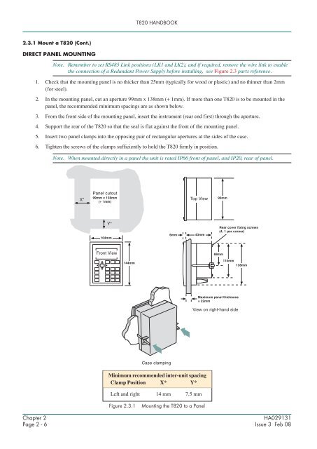
- Page 19: T820 HANDBOOK2.3.1Mount a T820The T
- Page 23 and 24: T820 HANDBOOK2.5.1CommunicationsETH
- Page 25 and 26: T820 HANDBOOKCHAPTER 3 GETTING STAR
- Page 27 and 28: T820 HANDBOOK3.1.4The opening displ
- Page 29 and 30: T820 HANDBOOK3.3 THE POP-UP MENUNot
- Page 31 and 32: T820 HANDBOOK3.4.2Responding to ala
- Page 33 and 34: T820 HANDBOOK3.5 THE ACCESS PAGEThi
- Page 35 and 36: T820 HANDBOOK3.5.1 Gaining access (
- Page 37 and 38: T820 HANDBOOKCHAPTER 4 CONFIGURATIO
- Page 39 and 40: T820 HANDBOOK4.2.1Preparing for the
- Page 41 and 42: T820 HANDBOOK4.3.1On-line Reconfigu
- Page 43 and 44: T820 HANDBOOK4.4 MODBUS CONFIGURATI
- Page 45 and 46: T820 HANDBOOKCHAPTER 5 CONTROL AND
- Page 47 and 48: T820 HANDBOOK5.2.1 Main pageThe Mai
- Page 49 and 50: T820 HANDBOOK5.2.2 Set Up page (Con
- Page 51 and 52: T820 HANDBOOK5.2.3 PID page (Cont.)
- Page 53 and 54: T820 HANDBOOK5.2.3 PID page (Cont.)
- Page 55 and 56: T820 HANDBOOK5.2.4 Tuning PageThis
- Page 57 and 58: T820 HANDBOOK5.2.4 Tune page (Cont.
- Page 59 and 60: 12345678901234567890123456789012123
- Page 61 and 62: T820 HANDBOOK5.2.4 Tune page (Cont.
- Page 63 and 64: T820 HANDBOOK5.2.5 SP page (Cont.)W
- Page 65 and 66: ○ ○ ○ ○ ○ ○ ○ ○ ○
- Page 67 and 68: T820 HANDBOOK5.2.6 OP page (Cont.)
- Page 69 and 70: T820 HANDBOOK5.3 EFFECT OF CONTROL
- Page 71 and 72:
T820 HANDBOOKCHAPTER 6 OPERATIONThi
- Page 73 and 74:
T820 HANDBOOK6.1.4Alarm Acknowledge
- Page 75 and 76:
T820 HANDBOOKCHAPTER 7 MANAGEMENTTh
- Page 77 and 78:
T820 HANDBOOK7.3 THE APPLICATION MA
- Page 79 and 80:
T820 HANDBOOK7.3.2Saving an applica
- Page 81 and 82:
T820 HANDBOOK7.3.4Loading or loadin
- Page 83 and 84:
T820 HANDBOOK7.4 THE FUNCTION BLOCK
- Page 85 and 86:
T820 HANDBOOK7.5 CONTROLLING ACCESS
- Page 87 and 88:
T820 HANDBOOK7.5.2 EDITING PASSWORD
- Page 89 and 90:
T820 HANDBOOK7.6.1 Editing communic
- Page 91 and 92:
T820 HANDBOOK7.6.1 Editing communic
- Page 93 and 94:
T820 HANDBOOK7.6.1 Editing communic
- Page 95 and 96:
T820 HANDBOOK7.6.2 Setting the star
- Page 97 and 98:
T820 HANDBOOK7.6.3Setting startup v
- Page 99 and 100:
T820 HANDBOOK7.7.1Changing Date and
- Page 101 and 102:
T820 HANDBOOK7.8 CHANGING LANGUAGE
- Page 103 and 104:
T820 HANDBOOK7.8.2Changing the Date
- Page 105 and 106:
T820 HANDBOOK7.8.4Changing the Dura
- Page 107 and 108:
T820 HANDBOOK7.9.1Contrast settings
- Page 109 and 110:
T820 HANDBOOK7.10 THE FILE MANAGER
- Page 111 and 112:
T820 HANDBOOKCHAPTER 8 TASK ORGANIS
- Page 113 and 114:
T820 HANDBOOK8.2 USER TASKS8.2.1Ter
- Page 115 and 116:
T820 HANDBOOK8.2.3 User task block
- Page 117 and 118:
T820 HANDBOOK8.4 DATA COHERENCE8.4.
- Page 119 and 120:
T820 HANDBOOKCHAPTER 9 EVENT LOGThi
- Page 121 and 122:
T820 HANDBOOKCHAPTER 10DATA MANAGEM
- Page 123 and 124:
T820 HANDBOOKCHAPTER 11SERVICEThis
- Page 125 and 126:
T820 HANDBOOK11.2.2 Battery replace
- Page 127 and 128:
T820 HANDBOOKAPPENDIX ASPECIFICATIO
- Page 129 and 130:
T820 HANDBOOKA.2.2 Hardware specifi
- Page 131 and 132:
T820 HANDBOOKA.2.3 Software specifi
- Page 133 and 134:
T820 HANDBOOKAPPENDIX B CUSTOMISING
- Page 135 and 136:
T820 HANDBOOKB.4 DATABASE NAMESEach
- Page 137 and 138:
T820 HANDBOOKB.5 DATABASE MONITORIN
- Page 139 and 140:
TERMINAL CONFIGURATOR HANDBOOKAPPEN
- Page 141 and 142:
TERMINAL CONFIGURATOR HANDBOOKC.2.1
- Page 143 and 144:
TERMINAL CONFIGURATOR HANDBOOKC.3.1
- Page 145 and 146:
TERMINAL CONFIGURATOR HANDBOOKC.3.1
- Page 147 and 148:
TERMINAL CONFIGURATOR HANDBOOKC.3.1
- Page 149 and 150:
TERMINAL CONFIGURATOR HANDBOOKC.3.3
- Page 151 and 152:
TERMINAL CONFIGURATOR HANDBOOKC.3.6
- Page 153 and 154:
TERMINAL CONFIGURATOR HANDBOOKC.3.6
- Page 155 and 156:
TERMINAL CONFIGURATOR HANDBOOKC.4.3
- Page 157 and 158:
TERMINAL CONFIGURATOR HANDBOOKC.4.5
- Page 159 and 160:
TERMINAL CONFIGURATOR HANDBOOKC.4.5
- Page 161 and 162:
TERMINAL CONFIGURATOR HANDBOOKC.4.5
- Page 163 and 164:
T820 HANDBOOKINDEXIndexSymbols.cnf
- Page 165 and 166:
T820 HANDBOOKLINOPC................
- Page 167:
Inter-Company sales and service loc