K-LC5 RADAR TRANSCEIVER Features Applications ... - RFbeam
K-LC5 RADAR TRANSCEIVER Features Applications ... - RFbeam
K-LC5 RADAR TRANSCEIVER Features Applications ... - RFbeam

Create successful ePaper yourself
Turn your PDF publications into a flip-book with our unique Google optimized e-Paper software.
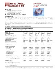
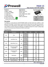
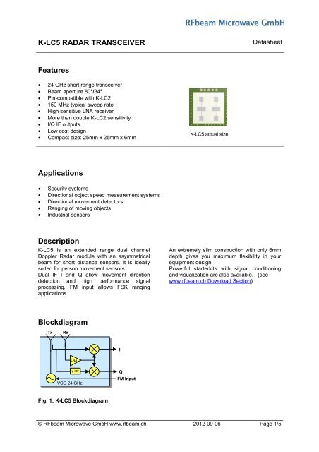
K-<strong>LC5</strong> <strong>RADAR</strong> <strong>TRANSCEIVER</strong> Datasheet<strong>Features</strong>• 24 GHz short range transceiver• Beam aperture 80°/34°• Pin-compatible with K-LC2• 150 MHz typical sweep rate• High sensitive LNA receiver• More than double K-LC2 sensitivity• I/Q IF outputs• Low cost design• Compact size: 25mm x 25mm x 6mmK-<strong>LC5</strong> actual size<strong>Applications</strong>• Security systems• Directional object speed measurement systems• Directional movement detectors• Ranging of moving objects• Industrial sensorsDescriptionK-<strong>LC5</strong> is an extended range dual channelDoppler Radar module with an asymmetricalbeam for short distance sensors. It is ideallysuited for person movement sensors.Dual IF I and Q allow movement directiondetection and high performance signalprocessing. FM input allows FSK rangingapplications.An extremely slim construction with only 6mmdepth gives you maximum flexibility in yourequipment design.Powerful starterkits with signal conditioningand visualization are also available. (seewww.rfbeam.ch Download Section)BlockdiagramTxRxILNAVCO 24 GHzQFM InputFig. 1: K-<strong>LC5</strong> Blockdiagram© <strong>RFbeam</strong> Microwave GmbH www.rfbeam.ch 2012-09-06 Page 1/5
K-<strong>LC5</strong> <strong>RADAR</strong> <strong>TRANSCEIVER</strong> DatasheetCharacteristicsParameter Conditions / Notes Symbol Min Typ Max UnitOperating conditionsSupply voltage V cc 4.75 5.0 5.25 VSupply current I cc 50 65 mAVCO input voltage U vco -0.5 2.0 VVCO pin resistance Driving voltage source Note 1 R vco 570 ΩOperating temperature T op -20 +80 °CStorage temperature T st -20 +80 °CTransmitterTransmitter frequency T amb=-20°C .. +60°C f TX 24.050 24.150 24.250 GHzFrequency drift vs temp. V cc=5.0V, -20°C .. +60°C Note 2 ∆ f TX -1.0 MHz/°CFrequency tuning range ∆ f vco 150 MHzVCO sensitivity S vco -80 MHz/VVCO Modulation Bandwidth B VCO 3 MHzOutput power EIRP P TX +12 +15 +19 dBmTurn-on Time Until oscillator stable Δf TX < 5MHz 1 1.5 µsSpurious emission According to ETSI 300 440 P spur -30 dBmReceiverAntenna gain F TX=24.125GHz Note 3 G Ant 8.6 dBiLNA gain F RX=24.125GHz G LNA 10 dBMixer Conversion loss f IF =1kHz, IF load 1k D mixer -9 dBReceiver sensitivity f IF =500Hz, B=1kHz, S/N=6dB, RLOAD P RX -103 dBmOverall sensitivity f IF =500Hz, B=1kHz, S/N=6dB D system -118 dBcIF outputIF output impedance R IF 50 ΩI/Q amplitude balance f IF =500Hz ∆U IF 3 dBI/Q phase shift f IF =500Hz ϕ 80 90 100 °IF frequency range -3dB Bandwidth f IF 0 50 MHzIF noise voltage f IF =500Hz U IFnoise 45 nV/√Hzf IF =500Hz U IFnoise -147 dBV/HzIF output offset voltage U os -0.2 +0.2 VSupply rejection Rejection supply pins to outputs, 500Hz D supply -25 dBAntennaHorizontal -3dB beamwidth E-Plane W ϕ 80 °Vertical -3dB beamwidth H-Plane W θ 34 °Horiz. sidelobe suppression D ϕ -12 -20 dBVert. sidelobe suppression D θ -12 -20 dBBodyOutline Dimensions connector left unconnected 25 x 25 x 6 mm 3Weight 4 gConnector 5 pinsNote 1 The VCO input has an internal voltage source with approx. 0.9VDC. For driving this pin it is necessary to source andsink currentNote 2 Transmit frequency stays within 24.050 to 24.250GHz over the specified temperatureNote 3 Theoretical value, given by design© <strong>RFbeam</strong> Microwave GmbH www.rfbeam.ch 2012-09-06 Page 2/5
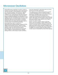
K-<strong>LC5</strong> <strong>RADAR</strong> <strong>TRANSCEIVER</strong> DatasheetOutline DimensionsFig. 3: Mechanical dimensionsApplication NotesSensitivity and Maximum RangeThe values indicated here are intended to give you a 'feeling' of the attainable detection range with thismodule. It is not possible to define an exact RCS (radar cross section) value of real objects becausereflectivity depends on many parameters. The RCS variations however influence the maximum rangeonly by 4 σ .Maximum range for Doppler movement depends mainly on:- Module sensitivity S: -118dBc (@1kHz IF Bandwidth)- Carrier frequency f 0: 24.125GHz- Radar cross section RCS ("reflectivity") of the object σ 1) : 1m 2 approx. for a moving person>50m 2 for a moving carnote 1) RCS indications are very inaccurate and may vary by factors of 10 and more.The famous "Radar Equation" may be reduced for our K-band module to the following relation:r =− s40.0167⋅10 40 ⋅ σUsing this formula, you get an indicative detection range of- > 15 meters for a moving person- > 40 meters for a moving carPlease note, that range values also highly depend on the performance of signal processing,environment conditions (i.e. rain, fog), housing of the module and other factors.By reducing IF amplifier bandwidth, detection range can be enhanced. With BW=250Hz instead of1kHz, sensitivity will raise by 6dB to -124dBc. Maximum range will then become 21m.You may achieve maximum range of more than 30m when using high resolution AD-converters andselective FFT algorithms.© <strong>RFbeam</strong> Microwave GmbH www.rfbeam.ch 2012-09-06 Page 4/5
K-<strong>LC5</strong> <strong>RADAR</strong> <strong>TRANSCEIVER</strong> DatasheetDatasheet Revision HistoryVersion Date Changes1.0 25-April-2012 initial release2.0 06 Sep-2012 K-<strong>LC5</strong> standard contains a VCO.K-<strong>LC5</strong>-v2 does not contain a VCO<strong>RFbeam</strong> does not assume any responsibility for use of any circuitry described, no circuit patent licenses are implied and<strong>RFbeam</strong> reserves the right at any time without notice to change said circuitry and specifications.© <strong>RFbeam</strong> Microwave GmbH www.rfbeam.ch 2012-09-06 Page 5/5