AN-04 Typical Doppler Signal Amplifier - Admiral Microwaves Ltd
AN-04 Typical Doppler Signal Amplifier - Admiral Microwaves Ltd
AN-04 Typical Doppler Signal Amplifier - Admiral Microwaves Ltd

You also want an ePaper? Increase the reach of your titles
YUMPU automatically turns print PDFs into web optimized ePapers that Google loves.
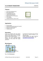
RFbeam Microwave GmbH<strong>AN</strong>-<strong>04</strong> <strong>Typical</strong> <strong>Doppler</strong> <strong>Signal</strong> <strong>Amplifier</strong>Power SupplyOutput signal of Radar sensors is influenced by the supply voltage. Because of the high gainamplification, supply voltage noise is visible at the amplifier output.Prefer using linear voltage regulator for sensor and amplifier supply.For power efficiency, consider using a dual stage approach with switch mode regulator followedby a linear regulator.Provide separate traces to amplifier and to digital power consumers. Blinking LED, processorand relais may cause interferences at the output of the high gain amplifier.<strong>Signal</strong> ProcessingPerformance of Radar based detectors depends on the quality of signal processing.ComparatorA simple comparator connected to the output of the amplifier may be sufficient for short distanceapplications.With a window comparator, we get better sensitivity as well as double frequency.Fig. 2: Principle of window comparatorFig. 3: Simple single comparatorFig. 4: Window comparatorComparator output may be connected to a retriggerable timer or to a micro-controller in order to get aconstant signal during movement.Output signal always contains noise. → Provide a hysteresis in the comparator circuit© RFbeam Microwave GmbH www.rfbeam.ch April 16, 2012 4/5
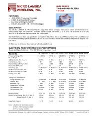
RFbeam Microwave GmbH<strong>AN</strong>-<strong>04</strong> <strong>Typical</strong> <strong>Doppler</strong> <strong>Signal</strong> <strong>Amplifier</strong>Digital ProcessingProcessing with comparators may be sufficient for many applications.Digital processing (FFT) however allows to get many more features and reliability:• Enhancing detection distance• Suppressing interferences (fluorescent lights, ventilators, ...)• Distinguishing objects (persons, vehicles, animals, ...)• Exact speed measurement• Multiple objects detectionI/Q Directional ProcessingSome RFbeam sensors provide I and Q outputs. This allows differentiating between approaching andreceding objects.Each channel must be amplified separately. Sensor output signals are phase shifted by +90° or -90°depending on the movement direction.I Q I QFig. 5: Approaching objectFig. 6: Receding objectTips And Hints• Use at least dual layer PCB with ground plane• Use separated ground traces for analog and digital parts• Place K-LCx sensor as close to the amplifier input as possible• Make signal lines as short as possible• Explore Radar basics using RFbeam ST100 starter kit or ST200 evaluation kit• Use RFbeam K-DT1 <strong>Doppler</strong> simulator to optimize your circuitOutput signals of Radar transceivers are often called 'IF' signals. This is an abbreviation ofIntermediate Frequency. The IF signal is created by mixing transmitter frequency (24GHz) withthe reflected signal from moving objects.The IF frequency is low and ranges typically from some Hz to some kHz (44Hz per m/s or 158Hzper km/h).In our application, IF signal is also called <strong>Doppler</strong> signal.Revision HistoryVersion 1.0 April 16, 2012 Initial ReleaseRFbeam does not assume any responsibility for use of any circuitry, principle or software described. No circuit patent licenses areimplied. RFbeam reserves the right at any time without notice to change said system and specifications.© RFbeam Microwave GmbH www.rfbeam.ch April 16, 2012 5/5