Basic Ohm's Law & Series and Parallel Circuits
Basic Ohm's Law & Series and Parallel Circuits
Basic Ohm's Law & Series and Parallel Circuits

Create successful ePaper yourself
Turn your PDF publications into a flip-book with our unique Google optimized e-Paper software.
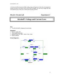
ENGINEERING lAB 1Variable resistor:1. Identify the end terminals <strong>and</strong> the wiper terminal for the potentiometer. Number them 1, 2<strong>and</strong> 3 with 2 being the wiper.2. Position the ohmmeter between terminals 1-2, 2-3 <strong>and</strong> 1-3 <strong>and</strong> record these measuredvalues in Table 1a-3.3. Add the values measured between terminals 1-2 <strong>and</strong> 2-3 <strong>and</strong> compare the result with thevalue measured between 1-3 (theoretical value).4. Reposition the shaft of the potentiometer <strong>and</strong> repeat steps 2 <strong>and</strong> 3 for the other two trials.Test (b). Voltage <strong>and</strong> Current MeasurementsAim:• To measure voltage <strong>and</strong> current in DC circuit.Apparatus:• DC voltage supply, 2k resistor, <strong>and</strong> two Digital Multimeters (2DMMs).Background:The test will familiarize you with the basic voltage <strong>and</strong> current measurements that is connectedto a dc power supply.Voltage Measurements• A voltemeter must always be connected with probes across the component under test;that is, the circuit need never be broken (see Figure 1b-1). This is often referred to asparallel connection.• Polarity : It is a good practice to place the correct leads at the proper nodes. Eg. Redlead at the positive node <strong>and</strong> the black lead at the negative node.Current Measurements• In measuring current (Figure 1b-2), the meter must always be inserted within the circuitin such a manner that the current to be measured will flow through the meter <strong>and</strong> itis similar to a series connection. You must break the circuit to perform a currentmeasurement.4
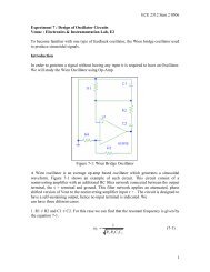
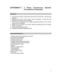
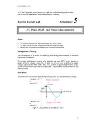
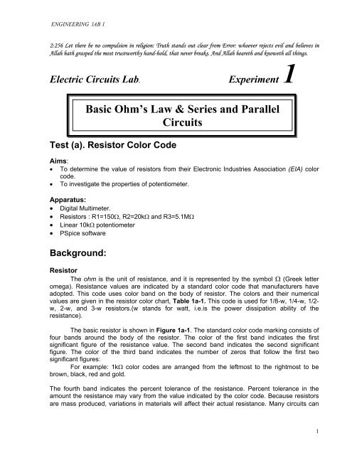
ENGINEERING lAB 15.0mAFigure 1b-3(10.00,5.00m)(6.00,3.00m)2.5mA(4.00,2.00m)(8.00,4.00m)(2.00,1.00m)0A0V 1V 2V 3V 4V 5V 6V 7V 8V 9V 10V-I(R1)VsVALMethod:1. Switch on the power supply <strong>and</strong> set for the minimum output voltage.2. Set the digital multimeter to measure voltage.3. Connect the voltmeter directly to the power supply terminals.4. Observe the effect of turming the output voltage control <strong>and</strong> adjust the voltage value to 2Volts.5. Remove the meter <strong>and</strong> connect 2kΩ resistor across the terminals of the power supply asshown in Figure 1b-1. Reconnect the meter as shown. Observe the value measured by themeter.6. Now break the circuit as shown in 1b-2 <strong>and</strong> insert the other meter set on mA currentrange.The meter will now be reading the current flowing in the circuit.7. Record the current in Table 1b-1.8. Increase the voltage in 2-Volt steps. For each of the voltage increment, measure <strong>and</strong> recordthe current changes.5
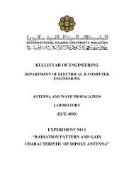
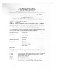
ENGINEERING lAB 1Test (c): Ohm’s <strong>Law</strong>Aims:• To verify Ohm’s law (V=IR).Apparatus:• Voltage dc supply, resistors 5.1kΩ <strong>and</strong> two digital DMMs.BackgroundOhm’s <strong>Law</strong> is the basis of many electrical circuit calculations which indicates V=IR. In thisexperiment Ohms <strong>Law</strong> has to be verified <strong>and</strong> will prove that the current through a resistor isproportional to the voltage across it. The way in which we accomplish this is to measure thevoltage across <strong>and</strong> the current through a known resistor for several different pairs of values.Data can then be plotted on a graph, <strong>and</strong> if the relationship is truly linear, it should yield astraight line.Figure 1c-1Method:1. Measure the actual value of the resistor R <strong>and</strong> record the result in Table 1c-1.2. Connect the circuit in Figure 1c-1 with R= 5.1kΩ.3. Beginning at 0 volt, increase the voltage across R in 1-Volt steps until 9 Volts. Measure <strong>and</strong>record the resulting current in Table 1c-1 for each increment of voltage.4. Plot the graphs of I verses V for results in Table 1c-1. (Assign I to the vertical axis <strong>and</strong> V tothe horizontal axis).5. Construct a right triangle on the grap, <strong>and</strong> from this, redetermine the slope <strong>and</strong> henceevaluate the conductance G.6. From this information, evaluate the resistance R. Record G <strong>and</strong> R for the graph in theappropriate column in Table 1c-2.7. Compared these experimentally obtained values with those measured values recorded inthe respective tables.Analysis, deductions <strong>and</strong> conclusion :1. Has Ohm’s law been verified?2. What are the facts supporting this decision?3. State the factors affecting resistance of a material with a uniform cross-sectional area ?4. What are the common types of a fixed <strong>and</strong> variable resistors? State usage of each type.6
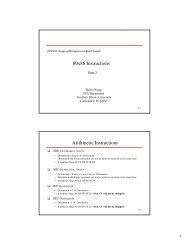
ENGINEERING lAB 15. Fill up the measured values in Table 1d-2.Analysis, deductions <strong>and</strong> conclusions:1. Have the aims been achieved?2. What are the facts supporting these decision for each point of the aim?3. What are the probable factors, which contributed to the discrepancies in the results for eachpoint of the aim?4. Indicate which circuit the principle of voltage division <strong>and</strong> current division is applicable to.5. State the formula for each condition.Pspice Analysis 21. Using PSpice <strong>and</strong> utilising the measured voltage supply <strong>and</strong> components values, display thevoltages <strong>and</strong> current values as shown in Figure 2-1a. Record the values in Table 1d-3.Assign proper titles to the schematics for submission.Figure 2-1a2. Using PSpice <strong>and</strong> utilising the measured voltage supply <strong>and</strong> components values, displaythe voltages <strong>and</strong> current values for Figure 2-2. Record the values in Table 1d-4. Assignproper titles to the schematics for submission.9
ENGINEERING lAB 1Table of ResultsResistor R1 R2 R3Nominal ValueTolerance%MaximumValueMinimumValueMeasuredValueTable 1a-2R1-2R2-3R1-3R1-2+R2-3I st trial 2 nd trial 3 rd trialTable 1a-3V supply (volt) 2 4 6Current (mA)Theoretical Valuesusing PSpiceCurrent (mA)Table 1b-110
ENGINEERING lAB 1Nominal ResistanceR=5.1kΩVoltage SourceCurrentTheoreticalCurrent Valuesusing PSpiceVs(V)(mA)(mA)Measured ResistanceR =0 1 2 3 4 5 6Table 1c-1Table 1c-1Slope (G)R (1/G)Theoretical Values usingPSpiceTable 1c-2Supply voltage(volt)V1(volts)V2(volts)V3(volts)Σ Voltage(volts)Supply current(mA)I1(mA)I2(mA)I3(mA)I Total(mA)Total resistance(Ohms)R1(Ohms)R2(Ohms)R3(Ohms)Σ RR1+R2+R3Table 1d-1Supply current(ampere)I1(amperes)I2(amperes)I3(amperes)Σ CurrentSupply voltage(volt)V1(volts)V2(volts)V3(volts)EquivalentresistanceR1(Ohms)R2(Ohms)R3(Ohms)EquivalentresistanceTotalconductanceG1(siemens)G2(siemens)G3(siemens)Σ GTable 1d-2.11
ENGINEERING lAB 1Calculated values ( PSpice Analysis)supplyvoltagetotalcurrentI1 I2 I3voltage drop over resistorR1 R2 R3(volts) (volts) (volts)Equivalent ResistanceTable 1d-3supplyvoltagetotalcurrentI1 I2 I3voltage drop over resistorR1 R2 R3(volts) (volts) (volts)Equivalent ResistanceTable 1d-412