
Create successful ePaper yourself
Turn your PDF publications into a flip-book with our unique Google optimized e-Paper software.
1 MEMORY CONTROLSIGNALS
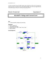
Connections Between CPU and MemoryControl signals8088 MemoryData BusAddress bus What are the control signals from the microprocessor to memory?What are the control signal from memory to the microprocessor? Address and data signals should be buffered—a buffer is a "midpoint holding place”, “temporary address / data holding” place—The use of buffers on address bus increases driving capability—The buffer allows each device or process to operate without being held up by theother-CPU operates faster then the memory devices, buffer used to store the address or data
Memory Control Signals : Minumim ModeControl Signals produced by 8088/8086 to support the interface memorysubsystemMin. mode of 8088 and 8086 = control signals produced for Input/Outputinterface circuitMax. mod , signals for IO and memory are not same. Min Mode of 8088 ( 8086 ):ALE, IO/M’, DT/R’, RD’,WR’,DEN’Which bus is carrying a valid address, direction of data transfer, when to readdata , when to write data IO/M’ is always =0 ; indicating a memory operation (IO’/M ; always logic 1)DT/R’ : 1 when transmiting mode & data is writing to memoryDT/R’ :0 when receiving mode ; readingRD’/WR’ : reading or writing bus cycle. DEN’ : to enable the data bus ( BHE ‘ ) SSO’ : indicating a code or data on transfer: Ex : mov ax, 1234
MINIMUM MODE 8088 MEMORY INTERFACEALEA 8 – A 19+5V8088MN/MX’AD 0 – AD 7RD’WR’IO/M’DT/R’DEN’Memorysubsystemand businterfacecircuitSSO’
Memory Control Signals : Maximum Mode8088/8086doesnot directly provide the control signals to support theinterface memory subsystem8088: WR’, IO/M’ ,DT/R’,DEN’,ALE and SSO’ replaced by:LOCK’ , S2’,S1’,S0’ , QS1,QS0, …S2’,S1’,S0’ signals 8288 : identifies which bus cycleCompared to IO, 8288 produces the following:AMWC’-- advanced memory write commandMWTC’-- memory write commandMRDC’ -- memory read commandOther control signals : ALE , DT/R’ , DENLock’ used to lock other processor to use the memory subsystemMemory bus cyclestatus codes
2 MEMORY READ AND WRITE BUS CYCLE
Read and write bus cycle
Read Bus CycleRead Bus Cycle8088 – min mode
Write Bus Cycle 8088- minmode
Status/Control signalactivity for 8086 max. mode
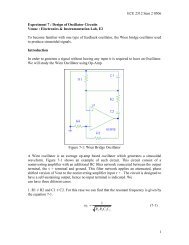
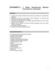
T1 T2 T3 T48086 Write CycleCLK/S0, /S1, /S2010 or 110A16..A19, /BHES3..S6ALEAddressStatusAD0..AD15AddressValid DataA0..A19Valid AddressDT/RDEN/MWTC or /IOWC
T1 T2 T3 T48086 Read CycleCLK/S0, /S1, /S2001 or 101A16..A19, /BHES3..S6AddressStatusALEAD0..AD15AddressfloatValid DatafloatA0..A19Valid AddressDT/RDEN/MRDC or /IORC
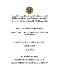
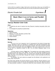
8086 Read Cycle (1 Wait StateT1 T2 T3 TwT4CLK/S0, /S1, /S2001 or 101A16..A19, /BHES3..S6ALEAddressStatus8284 RDYREADYAD0..AD15AddressfloatValid DatafloatA0..A19Valid AddressDT/RDEN/MRDC or /IORC
3 .MEMORY INTERFACE CIRCUIT
8088 minimum mode MIC block diagram- The address bus carries PA and selects which memory to be accessed- The data bus transfers data between 8088 and memory- The MIC is build from : Address Bus Latch, Data bus transceiver/latch ,address decoder-In case of 8088 additional bank write control logic and bank read controllogic is required
8086 maximum mode MIC block diagram-The MIC is build from : Address Bus Latch, Data bus transceiver/latch ,address decoder , bank write control logic and bank read control logic is required
Finally …. ( minimum ) 8086 or 8088 ?
Latching of Address Bus Address bus latch ic : 74373; octal latch device During T1 A0 – A19 is latched along with control signal BHE in the address bus latch. A17L – A19L are decoded ( via address decoder 74LS138 ) to produce CE0’ toCE7’ ALE is produced by 8288 buc controller , applied to CLK of 74373 A1L – A16L, CE0’ – CE7’ applied to the memory subsystem A0L applied to Bank Control Logi ( READ , WRITE ) to identify the which banks isbeen accessedBus Control Logic ( Write, Read ) determines which memory bank isaccessed MRDC’ – BCL –Read ( used during Read bus cycle ) MWTC’ - BCL Write ( used during Write bus cycle ) Bus Transeviers control the direction of the data transfer between 8086and memory subsystemDEN from 8288 is applied to EN of Data Bus trans.DT/R’ from 8288 is applied to DIR of Data Bus trans.
Address Latch circuit: = 74F3738 input signal pin8 output signal pinC = 1 ; O=IC=0; O = latch IOC’ = 0 ; output thelatchQuestion;How 20 bit input of 8086produce 20 latchedinput ?
Use 3 X 74F373 : Address Latch Circuit
Address bus with latch and Decoder
Bank Control Logic ( Read, Write )8086 memory : 2 banks ; upper, lower,Requires separate write and read control signals for the banks, WRu’ , WRl’ , RDu’,RDl’
Bank Write and Bank Read Control LogicBank Write Control LogicBank Read Control Logic
Data bus transceivers74F245 bidirectional octal bus transceiver : provide the buffering systemBidirectional input A1- A8, Bidirectional output B1- B8G’ enable buffer operation, DIR : direction ; logic 1 A to B ; otherwise,For 8086; 16 bit data we need 2 of this thing
Data Bus Transceiver Design ( 8086 )
Address Decoders 2 types 2-4 decoder : 74F139 ( select 1 out of 4 , given 2) 3-8 decoder: 74F138( select 1 out of 8 , given 3)
Note that G input is the control input that enables thedecoder.Once enabled, any of the four outputs (Y0 toY3) are selecteddepending on logic levels of inputs 'A’& ‘B’, as shownNote that due to the output inverters of the IC, whenselected,the outputs generated a logic low signal.373 ( adress latch outputs 3 signal (? ) to select CE0’ –CE 7’ … how to design ?
3 input 8 output decoder design using139
74LS 138 ( address decoder )
Put it together : last assignmentDraw a complete 8086 maximum modeMemory interface circuitUse colors, make sure abt the unidirectionaland bidirectional bus
4. . MEMORY SUBSYSTEMSTypes of memory Memory connections ( pin assignments )Memory DevicesMemory capacity and organizationsAddress decoding
Memory Address, Memory content
Primary and Secondary MemoryComputer memory is divided into primary memory and secondary memory.Primary memoryfast random access memory (RAM) ,read-only memory (ROM), Cache (?)RAM holds the programs and data that the processor is actively working with.ROM contains software that is used in Input/Output operations. It also containssoftware that loads the Operating System in Primary Memory.The CPU can read and write to RAM but it can only read from ROM.RAM is volatile while ROM is not.Secondary memory is used for long-term storage of programs and data.Examples of secondary memory devices are:hard disks, floppy disks and CD ROMs.Memory Hierarchy : organization of different memory level in computers
Primary and Secondary MemoryComparisonPrimary memoryFastExpensiveLow capacityConnects directly to theprocessorSecondary memorySlowCheapLarge capacityNot connected directly tothe processor
Memory Hierarchy
Memory TypesRAM (Random access memory): SRAM (Static RAM) (flip-flop gates)DRAM (Dynamic RAM)ROM (Read only memory) PROM (programmable)EPROM (erasable programmable)EEPROM (electronically erasable programmable), flash memory Generally, all memory devices have : address inputs and outputs, or just outputsa pin for selectionone or more pins that control the operation of the memory
Memory DevicesROM MemoryROM permanently stores programs and data that are resident to the system and must notchange when power is disconnected. This type of memory is often called nonvolatile memory,for example :EPROM (erasable programmable read-only memory) is programmed by an EPROMprogrammer and can be erased if exposed to ultraviolet light.The flash memory (EEPROM) is programmed in the system ( in circuit ) by using a 12Vprogramming pulseEach location can be written only 10,000 times.Programming of EEPROM takes more time than reading so it can not substitute RWMRAM : Read Access Memory, Read Write MemoryStatic RAM (SRAM) Devices retains data for as long as the system power system is attached. these memory types are available in sizes up to 128K x 8 stores temporary data and is used when the size of the read/write memory is relativelysmallDynamic RAM (DRAM) Memory the size is up to 16M x 1DRAM = SRAM, except that it retains data for only 2 or 4 ms on an integrated capasitor (seeFig. 9-7)Another disanvantage of DRAM memory is that it requires so many address pins that themanufacturers have multiplexed the address inputs
General descriptions of a Memory ChipAddress Connectionsare used to select one of the memory location within the deviceData Connectionsare used to enter information to be stored in a memory location and also to retrieveinformation read from a memory location.Manufacturers list their memory as, for example, 4K x 4, which means that the devicehas 4K memory locations (4096) and 4-bits are stored in each location.Selection ConnectionsMemory selection is accomplished via a chip selection pin (CS) on many RAMs or a chipenable pin (CE) on many EPROM or ROM memories ( see example in next slaids )Control ConnectionsMemory function is selected by an output enable pin (OE), for reading data.For writing data, memory function is selected by the write enable pin (WE).Address[log 2 (K)-1:0]K x NCSOEWMEMData[N-1:0]
Memory Connections: diagramAddress[log 2 (K)-1:0]K x NCSOEWEMEMData[N-1:0]Chip Select – must be asserted before Memory will respondto read or write operation. If negated, data bus ishigh impedance.OE – Asserted for read operation, Memory will drive datalines.WE – Asserted for a write operation (Memory inputs datafrom data pins).
Memory Capacity and Memory OrganizationK x NAddress[(log 2 (K)-1):0]MEMData[(N-1):0]x2K locations, N bits per location , Address bus has log 2 (K) address lines, data bus has N data lines.Chip capacity : number of bits a memory chipc can store , defined in bits , i.e. 1 Kbits, Mbits,( note : storage capacities of computer : Bytes)•memory chip has 64M : bits Computer has 64M : bytesMemory organization :• Each location can hold 1, 4 or 8 bits ( designed internally ) ; equal to # of data pin• How many location : address pins.2 x +y• referred as organization ; x is the number of address pins , y is number of bits in eachlocation
ExampleEx 1. MC has 12 address pin and 8 data pin, (a) organization ( b) capacityEx.2 A 512 MC has 8 pins for data (a) the organization (b) number of address pinsEx 3. Organization ? Capacity ? Of the following EPROM ?Ex.4 Intel 2716 has organization : 2K X 8. What is its capacity, how many address lines it has
Address DecodingTo attach a memory device to the microprocessor ( example see nextslide )To select particular set of addresses i.e. 00000 – 0FEEEto decode the address from the microprocessor to make the memoryfunction at a unique section or partition of the memory map.Why Decode Memory? To corrects the mismatch between microprocessor and memory component(because of a difference in the number of address connections surfaces) Commonly found address decoders include : the 3-to-8 Line Decoder (74LS138) the 74LS139 2-to-4 line decoder Simple logic gate Programmable Device : CPLD – complex programmable logic devices
1) Address decoding using simple NAND gateExercise:If a starting address is given as 90000(h), design a logic gate forCS’ of the above memory device
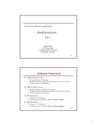
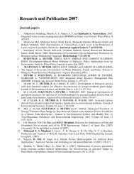
Address decoding using simple NAND gate Using partial memory addressing spaceFFFFFAddr[19:0]37FFF32KB Lowest address 0 0 1 1 0 0 0 0 0 0 0 0 0 0 0 0 0 0 0 03000000000Highest address0 0 1 1 0 1 1 1 1 1 1 1 1 1 1 1 1 1 1 1These 5 address linesare not changed. Theyset the base addressThese 15 address lines selectone of the 2 15 (32768) locationsinside the RAMsAddr[14:0]32KBAddr[19]Addr[18]Addr[17]Addr[16]Addr[15]IO/MCSCan we design a decoder such that the first addressof the 32KB memory is 37124H?
Semiconductor Memory Device Architecture• n×m Device– log 2 n inputs called “address lines”– m outputs called “data lines”Storage Cell ArrayA 12×4DecoderA 0D 14 x 5 Memory(4 locations, 5 bits perlocation).BuffersD 4 D 3 D 2 D 0
Using a decoder to connect to RAM
Address decoding using simple NAND gate Using partial memory addressing spaceFFFFFAddr[19:0]37FFF32KB Lowest address 0 0 1 1 0 0 0 0 0 0 0 0 0 0 0 0 0 0 0 03000000000Highest address0 0 1 1 0 1 1 1 1 1 1 1 1 1 1 1 1 1 1 1These 5 address linesare not changed. Theyset the base addressThese 15 address lines selectone of the 2 15 (32768) locationsinside the RAMsAddr[14:0]32KBAddr[19]Addr[18]Addr[17]Addr[16]Addr[15]IO/MCS
Address decoding using a address decoder
Address decoding using a programmable device
Exercise Show the calculation that verifies thataddresses 00000 to 9ffff(h) compromise640K
Data integrity How to ensure data retrieve is the same asthe data stored ?Checksum method : ROMParity bit method: DRAMCyclic Redundancy Check : Hard disk, datatransfer
Memory Address Decoding Design a 1MB memory system consisting of multiple memory chips— Solution 1:256KB 256KB 256KB 256KBCS CS CS CSAddr[17:0]Addr[18]Addr[19]2-to-4decoderCSIO/M
Design a 1MB memory system consisting of multiple memory chips— Solution 2:Memory Address Decoding256KB 256KB 256KB 256KBCS CS CS CSAddr[19:2]Addr[1]Addr[0]2-to-4decoderCSIO/M
Memory Address Decoding Design a 1MB memory system consisting of multiple memory chips— Solution 3:256KB 256KB 256KB 256KBAddr[19:18]CS CS CS CSAddr[16:7]Addr[5:0]Addr[17]Addr[6]IO/M2-to-4decoderCSIt is a bad design, but still works!Does it work if the last memory chip is removed?
Memory Address Decoding Design a 1MB memory system consisting of multiple memory chips— Solution 4:Addr[17:0]256KB 256KB 512KBCS CS CSAddr[18]Addr[19]IO/MAddr[18]Addr[19]IO/MIO/MAddr[18]Addr[19]