EXPERIMENT 5: 3 Phase Synchronous Machine Connected as a ...
EXPERIMENT 5: 3 Phase Synchronous Machine Connected as a ...
EXPERIMENT 5: 3 Phase Synchronous Machine Connected as a ...

You also want an ePaper? Increase the reach of your titles
YUMPU automatically turns print PDFs into web optimized ePapers that Google loves.
<strong>EXPERIMENT</strong> 5: 3 <strong>Ph<strong>as</strong>e</strong> <strong>Synchronous</strong> <strong>Machine</strong><strong>Connected</strong> <strong>as</strong> a GeneratorObjectives:1. Connect and operate a three ph<strong>as</strong>e synchronous machine <strong>as</strong> a synchronousgenerator2. Determine the value of the exciter current necessary, in order that thegenerator produces its nominal voltage3. Verify that the magnitude of the voltage generated depends on the excitercurrent and on the speed4. Explain why the speed of the drive machine decre<strong>as</strong>es when the excitercurrent is incre<strong>as</strong>ed5. Record the load characteristics6. Calculate the delivered apparent powerInstrument/Component1 3-ph<strong>as</strong>e salient-pole synchronous machine1 DC shunt wound machine1 Magnetic powder brake1 Control unit for brake1 Variable isolating transformer/exciter1 Variable dc power supply 0-240Vdc1 Field regulator for motor1 Starter1 Rubber Coupling sleeve1 Coupling guard1 Shaft end guard1 Cut-out switch, 3-pole2 Multimeter1 Set of connection cables1
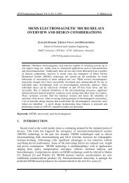
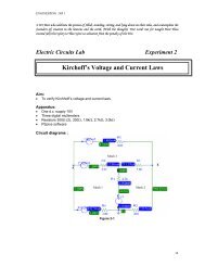
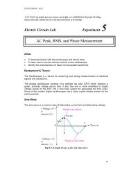
Circuit DiagramGroundVU 1V 1W 1W 2U 2V 2M/GL+F1F2DCVL-AFig 5.12
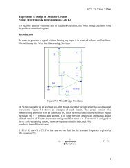
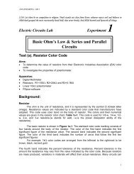
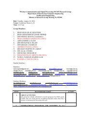
Nm min -1 X 10000 0TORQUE REVOLUTIONSSET/START VALUENmCONTR. MODE min -1 POWERx1 x2 x3MOLnMOTORSBRAKECONTROL UNIT FOR MAGNETIC POWDER BRAKE+ -VARIABLE ISOL . TRANSFORMER /EXCITERA2A1E2 E1A1M/GA2E2 E1SE2662-3AKΩ100W900ΩU1 V1 W1W2U2V2F2F110UAUSGU1 V1 W1U2 V2 W2M/GF1 F2START+-+-ST7007-5A3
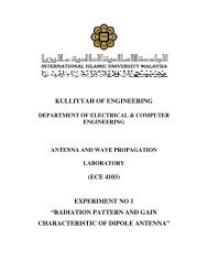
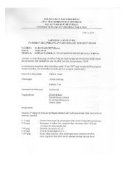
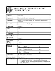
GroundAR BU 1V 1W 1W 2U 2V 2M/GL+F1F2DCVL-AFig 5.24
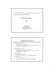
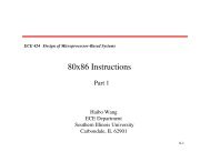
IntroductionIn a three ph<strong>as</strong>e synchronous generator, the magnitude of the generated off-loadvoltage is dependent on the speed and the exciter voltageThe rotor of the generator is driven by the drive machine. A static magnetic field,with respect to the rotor, is produced in the exciter winding by a dc voltageA rotating field is produced in the stator due to the rotation of the rotor, whichinduces voltages in the stator windings, 120 o out of ph<strong>as</strong>e with each other. Thegenerator thus produces a three ph<strong>as</strong>e voltageA dc shunt wound machine is recommended <strong>as</strong> drive machine because ofsimplicity in its connection and good control of the revolution speed whichremains relatively constant over a wide range with incre<strong>as</strong>ing loads. Connectionof the drive motor is shown belowL+tR FsR AA1ME1E2A2L-PEFig 5.35
Exercise1. Construct the circuit <strong>as</strong> shown in the fig. 5.1.2. Set the control unit <strong>as</strong> follows:a) Speed n = 1500 rpmb) Torque M = 1Nmc) Operating Mode M = constantAdjust the start/set value, so that the machine starts up with a minimumload applied.Range on multimetersGenerator voltageExciter currentExciter voltageV = 1000V acI = 1A dcV = 300V dcAdjust the speed to 1500 rpm using the supply voltage, field regulator andstarter. This speed must be kept constant throughout all the me<strong>as</strong>urements.3. Set the exciter current to the values given in the table 5.1, commencing at150mA. Me<strong>as</strong>ure the generated voltage and enter the value into table 5.1N (rpm) 1500I exc (mA) 150 180 250 350 500 650 800V exc (V) 39 45 62 86 125 165 210V GTable 5.14. Adjust the exciter current to 700mA. Keep this value constant during theme<strong>as</strong>urement by adjustment of the supply voltage, set the speed to thevalues given in table 2, commencing at 800 rpm. Me<strong>as</strong>ure the generatorvoltage and enter the value into the table 5.2I exc (mA) 700V exc (V) 210N (rpm) 800 1000 1250 1500 1750 2000V GTable 5.26
5. Connect the machine shown in Fig 5.2.6. Set the load resistance to 4kΩ and switch on the drive machine. Adjust thesupply voltage for a drive machine speed of 1500 rpm. This speed must bekept constant during all me<strong>as</strong>urements7. Switch the exciter unit and adjust the exciter voltage of 140V. This excitercurrent must be kept constant during all me<strong>as</strong>urements8. Load the generator by reducing the load resistance, to obtain the values ofcurrent flow <strong>as</strong> given in table 5.3 below. Me<strong>as</strong>ure the voltage generated andcalculate the apparent power producedP app = V.I.3 1/2Enter the me<strong>as</strong>ured and calculated values into the tableN (rpm) 1500V exc (V) 140I (mA) 70 100 120 170 200 230 250V GP app (VA)Table 5.39. From the me<strong>as</strong>ured and calculated values, plot the load characteristics:a) For table 5.1 : V G (V) vs V exc (V)b) For table 5.2 : V G (V) vs N (rpm)c) For table 5.3 :i) V G (V) vs I (mA)ii) P app (VA) vs I (mA)7
Question1. Explain why the speed of the drive machine decre<strong>as</strong>es when the excitercurrent incre<strong>as</strong>e?2. What is the effect of loading on the generator voltage?8