EE160 LAB2: BJT Bias. Stability Analysis.
EE160 LAB2: BJT Bias. Stability Analysis.
EE160 LAB2: BJT Bias. Stability Analysis.

You also want an ePaper? Increase the reach of your titles
YUMPU automatically turns print PDFs into web optimized ePapers that Google loves.
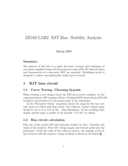
<strong>EE160</strong> <strong>LAB2</strong>: <strong>BJT</strong> <strong>Bias</strong>. <strong>Stability</strong> <strong>Analysis</strong>.Spring 2009SummaryThe purpose of this lab is to apply the basic concepts and techniques ofmicrowave amplifier design with S-parameters using ADS. DC characteristicsand S-parameters of a microwave <strong>BJT</strong> are analyzed. Stabilizing circuit isdesigned to achieve unconditionally stable 2-port network.1 <strong>BJT</strong> bias circuit1.1 Curve Tracing. Choosing Q-point.When creating a new design choose the <strong>BJT</strong> curve tracer template. In thecomponent library::RF transistor library::Packaged <strong>BJT</strong> choose pb hp AT41435transistor and position it in the proper place in the schematics.In the “Parameter Sweep” properties choose the range for the base current:from 0 to 50uA with step of 2uA. The collector emitter voltage rangeshould be set to 0 to 15V in the . Run Simulation. In the resulting Datadisplay window place a marker in the Q-point: Vce=8V, Ic=10mA.1.2 <strong>Bias</strong> circuit calculationPick one of the passive DC bias networks studied in class. Calculate thevalues of the resistors. Place DC voltage supply and Current probe into theschematics. Verify the value of the collector current. An example of the dcbias network with the negative voltage feedback is shown in the Figure 1.1
Figure 2: Schematic window for S-parameter measurements and stabilityanalysis.Figure 3: <strong>Stability</strong> analysis. Output stability circles.3
3 Stabilizing transistor.Place stabilizing resistor either in the input or the output. Try to stabilize thetransistor (µ > 1) across all frequencies while maximizing the S21 parameterat 2 GHz. You can experiment with L and C components in the stabilizingcircuit. Use tuner and/or optimization. Specify frequencies and loads forwhich transistor is not stable.4