Integrated Transceivers for Optical Wireless Communications
Integrated Transceivers for Optical Wireless Communications
Integrated Transceivers for Optical Wireless Communications

You also want an ePaper? Increase the reach of your titles
YUMPU automatically turns print PDFs into web optimized ePapers that Google loves.
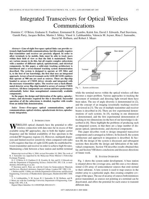
IEEE JOURNAL OF SELECTED TOPICS IN QUANTUM ELECTRONICS, VOL. 11, NO. 1, JANUARY/FEBRUARY 2005 173<strong>Integrated</strong> <strong>Transceivers</strong> <strong>for</strong> <strong>Optical</strong> <strong>Wireless</strong><strong>Communications</strong>Dominic C. O’Brien, Grahame E. Faulkner, Emmanuel B. Zyambo, Kalok Jim, David J. Edwards, Paul Stavrinou,Gareth Parry, Jacques Bellon, Martin J. Sibley, Vinod A. Lalithambika, Valencia M. Joyner, Rina J. Samsudin,David M. Holburn, and Robert J. MearsAbstract—Line-of-sight free-space optical links can provide extremelyhigh bandwidth communications, but this usually requiresthat transmitter and receiver are precisely aligned. In order toallow terminals to be mobile, links must be able to track userswithin their field of view so that the link is maintained. Thereare various means to do this, but all require complex subsystemswith a number of different optical, optoelectronic, and electricalcomponents. In this paper, a solid-state tracking architecture isintroduced and a seven-channel tracking system demonstrationdescribed. The system is designed to operate at 155 Mb/s andis, to the best of our knowledge, the first that uses an integratedapproach. Arrays of novel resonant cavity LED (RCLED) emittersthat operate at 980 nm are used as sources. These are flip-chipbonded to arrays of CMOS driver circuits and integrated withthe necessary transmitter optics. The receiver uses a back-illuminateddetector array flip-chip bonded to arrays of custom CMOSreceivers. All these components are custom and have per<strong>for</strong>mancesubstantially better than nonoptimized commercially availablecomponents.In the paper, the design and fabrication of the optics, optoelectronics,and electronics required <strong>for</strong> this is described. Successfuloperation of all the subsystems is detailed, together with resultsfrom an initial link demonstration.Index Terms—Free-space optical communications, opticalcommunications, optical wireless, optoelectronic devices, optoelectronicintegration.I. INTRODUCTIONWIRELESS optical channels have the potential to offerwireless connection with data rates far in excess of thatavailable using RF approaches, due to both the higher carrierfrequency and the limited availability of free spectrum in thecrowded RF frequency regions [1]. However, multipath dispersionand limited receiver sensitivity when compared with radioLANs requires that line-of-sight (LOS) paths be established betweentransmitter and receiver in order to achieve high bit rates.Maintaining a link between a base station and mobile terminalManuscript received May 4, 2004; revised November 10, 2004. The work ofR. J. Samsudin was supported by the Malaysian Prime Minister’s FellowshipExchange Program.D. C. O’Brien, G. E. Faulkner, E. B. Zyambo, K. Jim, and D. J. Edwards arewith the Department of Engineering Science, Ox<strong>for</strong>d OX1 3PJ, U.K. (e-mail:dominic.obrien@eng.ox.ac.uk).P. Stavrinou and G. Parry are with the Centre <strong>for</strong> Semiconductor Materialsand Devices, Blackett Laboratory, Imperial College, London SW7 2BZ, U.K.J. Bellon and M. J. Sibley are with the Department of Electronic and ElectricalEngineering, University of Huddersfield, Queensgate, Huddersfield HD1 3DH,U.K.V. A. Lalithambika, V. M. Joyner, R. J. Samsudin, D. M. Holburn, and R.J. Mears are with the Cambridge University Department of Engineering, CambridgeCB2 1PZ, U.K.Digital Object Identifier 10.1109/JSTQE.2004.841471Fig. 1.System architecture.while the terminal moves within the optical wireless cell thenbecomes a major problem. Various approaches to tracking themovement of terminals and directing light toward them havebeen taken. The use of angle diversity is demonstrated in [2],and the concept of an imaging (essentially tracking) receiveris reviewed in [3]. The use of multiple transmitter and receiverbeams is described in [4]. There are few experimental demonstrationsof such systems. In [5], tracking in one dimensionis demonstrated, and the first experimental demonstration oftracking in two dimensions (to the best of our knowledge) is describedin [6]. These highlight the problems of producing suchan integrated system, in that there are a large number of disparateoptical, optoelectronic, and electrical components.This paper describes work to design integrated transceivercomponents and is arranged as follows. In Section II, the systemarchitecture and approach to integration is described. In SectionIII, the design of the system is discussed; and subsequentsections then describe the design and fabrication of the individualcomponents. Section VII describes results obtained thusfar, and Section VIII draws conclusions and discusses directionsof future work.II. SYSTEM OVERVIEWFig. 1 shows the system under development. A base stationis situated above the coverage area, and this uses a two-dimensional(2-D) array of semiconductor sources that emit normalto their substrate. A lens system is used to map sources in theemitter array to a particular angle, thus creating complete coverageof the space. The use of an array of sources both minimizespower transmitted, as sources not pointing at a terminal can bedeactivated, and offers the potential <strong>for</strong> each source to transmitdifferent data.1077-260X/$20.00 © 2005 IEEE
174 IEEE JOURNAL OF SELECTED TOPICS IN QUANTUM ELECTRONICS, VOL. 11, NO. 1, JANUARY/FEBRUARY 2005Fig. 2.Approach to integration.Each terminal within the space has a lens system that collectsandfocusesthebeamoflightontoaparticulardetectorwithinadetectorarray. The resulting electrical signal is amplified and a datastream is extracted from it. The detector array allows the angle ofarrival of the beam to be determined and, hence, the direction ofthe required uplink (from terminal to base station). The system is,there<strong>for</strong>e, a combination of a tracking transmitter and tracking receiver.This has the potential to maximize the power available atthe receiver (when compared with combinations of tracking andnontracking components).Each detectorhaslow capacitanceanda narrow field of view, thus increasing channel bandwidth and reducingthe effect of ambient illumination.Fig. 2 shows the approach taken to integration. Arrays ofsources that emit through their substrate are flip-chip bonded toarrays of driver electronics fabricated in a “commodity” CMOSprocess. This provides the transmitter functionality, and a similarapproach is taken with the receiver photodetector array.Particular features of this approach make it amenable to largescaleintegration.1) Scalability. The flip-chip bonding of drivers and receiversdirectly under the detector arrays within the area requiredensures the basic driver and receiver units are scalable tolarge numbers of elements. This integration can take placeat a wafer scale.2) Functionality. The CMOS process used <strong>for</strong> the electronicsallows complex digital control circuitry to be integratedwith the analog receiver and transmitter electronics3) Cost. The electronic circuits use a low-cost CMOSprocess, and the optoelectronic devices can be producedand tested on a wafer scale [7].III. SYSTEM DEMONSTRATIONIn order to demonstrate these ideas, a seven-channel demonstrationhas been fabricated and tested. The system is designedto operate at 155 Mb/s, using Manchester coding. This waschosen because it is relatively robust to any low-frequency electricalnoise caused by inadvertent detection of ambient artificialillumination, due to the small amount of energy in its spectrumthat is present at these low frequencies. Manchester coding alsoallows straight<strong>for</strong>ward clock recovery, and as the focus of thework described here is the transceiver components, more complexcodes were not considered.The link is designed to operate over several meters using approximately0 dBm of transmission power, with a target receiversensitivity of approximately 30 dBm, and will track over afield of view of approximately 14 at this distance.The system operates at 980 nm as substrate emitting deviceswere available at this wavelength, and the materials systemsrequired to fabricate these are well understood. At wavelengthsbeyond 1400 nm, eye safety regulations allow more than anorder of magnitude more power to be emitted than at 980 nm,and the receivers are designed to operate at these longerwavelengths. Suitable arrays of surface normal emitters areunavailable, however. Initial examples of emitters operating atthis wavelength have been grown under the program, but arenot at a sufficiently advanced level <strong>for</strong> integration.In the following sections each of the components is describedin detail.A. EmittersIV. OPTOELECTRONIC DEVICESThe system requires 2-D arrays of surface emitters that emitthrough the semiconductor substrate, thus making devices suitable<strong>for</strong> flip-chip bonding. Both vertical cavity surface-emittinglasers (VCSELs) [8] and resonant cavity LEDs (RCLEDs) [9],[10] are suitable <strong>for</strong> this application. In this case, RCLEDs havesufficient modulation bandwidth, an emission profile that canbe optimized <strong>for</strong> this application, and a simpler structure thanthat a VCSEL. This is particularly relevant <strong>for</strong> operation at longwavelength, where growth of the mirror structures represents aconsiderable technical challenge.1) Device Structure: Fig. 3 shows the structure of the LED.The emitter devices are metal/semiconductor hybrid RCLEDsdesigned on the basis of previous work [9], [11] . The structuresare epitaxially grown by molecular beam epitaxy (MBE) ondouble polished n+ GaAs wafers and emit through the substrate,which is nominally transparent at these wavelengths. The activelayers in the cavity are three or four strained In Ga As () quantum wells (QWs) clad by GaAs barrier layers. Thebottom mirror is a multiple quarter-wave stack of GaAs/AlAslayers, known as a distributed Bragg reflector (DBR). The cavityis completed by the deposition of a metal mirror on the uppersurface of the multilayer structure shown. For this device structure,the typical on-axis linewidth is 20–30 nm around 980 nm.A key property of RCLEDs <strong>for</strong> this type of application is theability to determine the emission angular beam profile by designingthe emission wavelength of the QWs inside the cavityto be approximately 10–20 nm shorter than the resonance wavelengthof the cavity. The emission wavelength is predominantlygoverned by the width of the QWs and the indium mole fraction,while the cavity resonance wavelength is determined by the aggregateoptical thickness of the layers between the metal topmirror and the bottom DBR. The offset in the two wavelengthsis known as detuning, and the degree of detuning affects the
O’BRIEN et al.: INTEGRATED TRANSCEIVERS FOR OPTICAL WIRELESS COMMUNICATIONS 175Fig. 3.Structure of RCLED.Fig. 5. (a) DC characteristics of RCLED. (b) Eye diagram <strong>for</strong> RCLEDmodulated at 310 Mb/s. (c) Simulated and measured beam profile of RCLED.Fig. 4.RCLED array suitable <strong>for</strong> flip-chip bonding.beam profile of the emission. A detailed simulation of the opticalsystem was undertaken in order to determine the optimumdetuning <strong>for</strong> this application, and this is described in Section VI.Wafers were grown at the University of Sheffield, Sheffield,U.K., using metal–organic vapor phase epitaxy (MOVPE),and areas of the wafer with the optimum degree of detuning( 20 nm) identified. Appropriate material was then processedinto seven-element hexagonal pitch arrays using standardlithography techniques. The devices are on a 400- m pitch, andare suitable <strong>for</strong> flip-chip bonding. Fig. 4 shows one example;the central seven contacts are to the p-device terminal and theperipheral contacts are used as a common cathode connection.Additional thin ( 20-nm) layers of platinum were used toprotect the contacts on the device from the solder used inflip-chip bonding.2) Device Per<strong>for</strong>mance: The optical power versus currentand voltage versus current characteristics <strong>for</strong> the RCLEDs <strong>for</strong> atypical device are shown in Fig. 5(a). Device efficiency was approximately0.6% <strong>for</strong> 100-mA drive current, with output powerof approximately 1.75 mW and a slope resistance of around 3<strong>for</strong> devices that gave the maximum output optical power. Furtheroptimization should lead to more efficient devices, but thesedevices have sufficient per<strong>for</strong>mance <strong>for</strong> this application.
176 IEEE JOURNAL OF SELECTED TOPICS IN QUANTUM ELECTRONICS, VOL. 11, NO. 1, JANUARY/FEBRUARY 2005Fig. 6.Photodetector structure.Fig. 5(b) shows an eye diagram <strong>for</strong> a device that is biasedusing a constant current driver and modulated using a 310-Mb/spseudorandom binary sequence. This shows that the RCLEDshave sufficient bandwidth <strong>for</strong> this application. Fig. 5(c) showsthe simulated and actual measured beam profile from a typicaldevice. The measured profile is a closest match to the simulatedresult <strong>for</strong> the highly detuned devices, showing the particulararray uses a highly detuned portion of the wafer.B. Detectors1) Detector Structure: The system requires a close-packedarray of hexagonal detectors that are illuminated through theirsubstrate, and the per<strong>for</strong>mance of these detectors is one of thekey design constraints. In a system where the transmitter beam islarger than the receiver collection aperture, the power collectedwill usually be proportional to the detector area <strong>for</strong> any givenoptical system. However, increasing detector area increasesthe capacitance presented to the system preamplifiers, whichreduces the available bandwidth. A major focus of this workhas been in optimizing detector structures <strong>for</strong> this free-spaceapplication. An optimum detector <strong>for</strong> optical wireless wouldbalance transit time and capacitance controlled bandwidth andachieve maximum area <strong>for</strong> a given bandwidth. Epitaxiallygrown structures such as that grown here allow independentcontrol of depletion width and field by the growth of Intrinsic(I) regions of the correct thickness, so that this should bepossible. Preliminary modeling of an InGaAs p-i-n structureshows that a 30- m I region could offer bandwidths of 1GHz <strong>for</strong> a 1-mm device (assuming a 50- amplifier inputimpedance). This is a <strong>for</strong>midable challenge, due to the problemsin controlling doping in such thick structures, and in the devicesgrown <strong>for</strong> this work, the I region was limited to a 5- m layer.Optimized detectors might also include filtering layers to reducethe noise from optically broadband ambient illumination, andpreliminary structures that show filtering action have beengrown [12]. However, these proved to be too capacitive andsimpler p-i-n structures were grown <strong>for</strong> the demonstrator.Fig. 6 shows the p-i-n photodiode structures grown <strong>for</strong> thereceiver subsystem. These are substrate illuminated InGaAs/InPp-i-n diodes grown on InP substrates by MOVPE. These areFig. 7.Seven-channel detector array suitable <strong>for</strong> flip-chip bonding.designed <strong>for</strong> substrate illumination and operation in the rangefrom 980 to beyond 1500 nm. The structure incorporates a topcontact that also acts as a mirror, which ensures that unabsorbedphotons are reflected back into the detectors, thus increasingtheir responsivity.Wafers were processed into seven-element hexagonal pitcharrays, with close-packed devices on a 500- m pitch. Devicesize and, hence, pitch was chosen from optical design considerationsand to ensure the maximum capacitance presented to thereceivers was within their design specification.2) Device Per<strong>for</strong>mance: Devices typically have a measuredcapacitance of 5.2 pF (at 4-V reverse bias) compared with acalculated value of 5.1 pF <strong>for</strong> a fully depleted I region. The slightdiscrepancy is due to the reduced bias voltage (4 V) comparedto that required to fully deplete the I region (estimated to beapproximately 8 V). This is a factor of five lower than typicalcommercial devices, showing the importance of optimizingdevices <strong>for</strong> this application. The measured responsivity was 0.39A/W at 980 nm, compared with a theoretical maximum of 0.79A/W. Two factors contribute to the reduction in responsivity: theInP substrate has significant absorption at this wavelength, andthe Fresnel losses ( 30 ) as light enters the semiconductorsubstrate reduce the illumination incident on the p-i-n structure.An estimate of the likely reduction these two effects produceleads us to believe the detectors are operating efficiently.Fig. 7 shows a picture of a seven-channel detector array witha 500- m pitch that is suitable <strong>for</strong> flip-chip bonding. As was thecase <strong>for</strong> the emitters, a number of protective metal layers weregrown on top of the basic detector structure in order to stop golddiffusing into the solder bumps.V. SILICON DESIGNA. TransmittersFig. 8(a) shows a block diagram of the RCLED driver circuitthat is used to drive each source. The core function of the driveris voltage-to-current conversion to produce modulating <strong>for</strong>wardcurrent from a voltage data signal. The modulation circuit inthe driver consists of a voltage-to-current transducer and a
O’BRIEN et al.: INTEGRATED TRANSCEIVERS FOR OPTICAL WIRELESS COMMUNICATIONS 177Fig. 8.(a) RCLED driver circuit block diagram.(b) Eye diagram derived from optical output of RCLED and driver modulated at 100 Mb/s.current mirror with a suitable amplification factor to producethe necessary output levels. In addition, the driver incorporatesintegrated speedup capabilities aimed at improving the opticalsource’s turn-on and turnoff times. These are implementedusing three circuits: namely, the bias, charge injection, andcharge extraction circuits, the latter two employing the useof novel pulse generators. The bias circuit supplies a smallquiescent current to the RCLED at all times and, thus, keepsthe space-charge capacitance of the source constantly charged.This effectively reduces the delay of carrier injection into theactive region [13] after stimulation of the optical source with apulse, thereby minimizing delay in light output. Charge injectionworks by introducing a large current spike at each positiveedge of the data signal, which reduces the optical rise time ofthe emitter [14]. Similarly, charge extraction improves opticalfall time by sweeping out carriers from the active region of theemitter [15], [16] through the introduction of a negative currentspike at each falling edge of the data signal. Charge injectionand extraction are implemented using pulse generators thatconsist of delay elements and logic gates [as shown in Fig. 8(a)]to generate short-duration digital pulses at specific instancesof the data signal. The charge injection pulse generator usesa NAND gate to trigger on the positive edge of the data signal,which is the instance at which the emitter must turn on. Thisthen creates a short-width pulse that is subsequently convertedto a large current spike coinciding with the turn-on instance ofthe light source. The generator <strong>for</strong> charge extraction utilizes aNOR gate to generate a short-width pulse on the falling edgeof the data signal coinciding with the turnoff instance of thesource. Each driver is designed to source 100 mA of <strong>for</strong>wardcurrent at 1.5 V <strong>for</strong>ward voltage, which would yield 2.5 mW ofoptical output power with device efficiencies of around 1.7%.Single channel driver test structures have been fabricated ina CMOS 0.7- m technology and tested using infrared LEDs[17]. DC tests show that the CMOS devices can source thenecessary current to drive and prebias the RCLEDs. Fig. 8(b)shows a 100-Mb/s [nonreturn-to-zero (NRZ)] eye diagram froma CMOS driver and RCLED showing excellent per<strong>for</strong>mance.This may be limited by inductance in the wirebonds betweendriver and source. There is an estimated 6 nH of inductance,which combined with the 100-mA drive current that is sourcedin several nanoseconds might lead to a substantial drop in the2 V applied to the LEDs. When the driver is integrated withthe RCLEDs using flip-chip bonding, we expect to see muchimproved per<strong>for</strong>mance. Such fully integrated devices are nowcomplete and awaiting testing.
178 IEEE JOURNAL OF SELECTED TOPICS IN QUANTUM ELECTRONICS, VOL. 11, NO. 1, JANUARY/FEBRUARY 2005Fig. 9.Transimpedance amplifier circuit diagram.B. Receivers1) Transimpedance Amplifier: A major ef<strong>for</strong>t has been thedesign of the receiver preamplifier circuit, shown in Fig. 9. Thedetails of its design are outlined in [18]. A transimpedance amplifierstructure is used and consists of a three-stage voltage amplifierwith shunt resistive feedback. This approach provides thebest compromise in terms of noise, gain, and bandwidth, all ofwhich are influenced by the capacitance of the detector. Eachstage of the amplifier is identical and consists of an inverter stagewith diode-connected load. This topology has several design advantages.The inverter, compared to a single device, produces ahigher transconductance <strong>for</strong> a given bias current. Furthermore,the diode-connected load is used to trade off the gain of the unloadedinverter <strong>for</strong> increased small-signal bandwidth. The transimpedancebandwidth is governed by the input capacitance,open loop gain of the amplifier, and the feedback resistance. Inorder to account <strong>for</strong> variances in the detector capacitance andparasitics, a variable feedback resistor is implemented using apositive channel MOS (PMOS) transistor biased in the linear region.The resistance can be varied by applying a voltage biasto the gate of the transistor in order to achieve the required bandwidthand maintain stability over a range of 2–10 pF of capacitanceat the input.The preamplifier circuit was fabricated using a 0.7- mCMOS process technology, offered through the Europracticeinitiative. With a total input capacitance (including detectorand parasitics) of 10 pF, the transimpedance amplifier achievesa measured bandwidth of 217 MHz and transimpedance gainof 4.2 k . This compares extremely favorably with [19] whichreports a 156-Mb/s receiver with a 2.5-pF input capacitance.Noise per<strong>for</strong>mance of the circuit was measured by comparingthe output noise spectra with and without input signal in orderto remove the effect of measurement noise, as proposed byCarruthers [20]. The measured input-referred noise currentdensity is 5.92 pA Hz. At a bandwidth of 217 MHz, usingthe measured detector responsivity of 0.39 A/W, this impliesa sensitivity of approximately 29 dBm at 980 nm. Fig. 10(a)shows a 310-Mb/s eye diagram receiver output, showing goodper<strong>for</strong>mance at this data rate. Calculations indicate that avariation in optical power of approximately 22 dB can be accommodatedby the preamplifier, but due to the limited sourcepower available, this was only verified by measurement over a7.5-dB range.Fig. 10. Eye diagrams <strong>for</strong> transimpedance amplifier operating at 310 Mb/s andlater design operating at 1 Gb/s.2) Gigabit Receiver: In order to investigate extending theproposed receiver architecture to Gb/s data rates, a receiver ICoperating at 1 Gb/s was developed and realized in a 0.35- mCMOS process. The chip includes two transimpedance amplifierstages; one is a common-source input stage, and the othera current-mode common-gate input stage. The low input resistanceof the common-gate stage has many potential advantages,as the large detector capacitance can be decoupled fromthe bandwidth and gain of the preamplifier, ultimately leadingto lower noise. Theoretical analysis presented in [21] showsthat the per<strong>for</strong>mance improvement offered by the common-gatestage is limited when implementing the receiver in a standardCMOS technology operating at a single, low supply voltage.Furthermore, isolating the large photodiode capacitances expectedin optical wireless receivers can lead to large junctioncapacitances that further degrade per<strong>for</strong>mance and hinder designoptimization. Electrical measurements were carried out onboth preamplifier topologies using a detector emulation circuitat the input of each channel with an associated capacitance of 6pF. Best results were achieved on the common-source channel.The common-source preamplifier achieves a gain of 44.6 dB,3-dB bandwidth of 500 MHz, and an input-referred currentnoise power spectral density (PSD) of 14.8 pA Hz; good eyeopenings have been demonstrated at bit rates up to 1 Gb/s asshown in Fig. 10(b).
O’BRIEN et al.: INTEGRATED TRANSCEIVERS FOR OPTICAL WIRELESS COMMUNICATIONS 179Fig. 11. (a) Diversity receiver block diagram. (b) Transconductance amplifierschematic.3) Diversity Receiver: In order to recover data from the incomingoptical power, the signal from the desired detector orgroup of detectors must be routed to the data recovery circuit.A combiner circuit that allows arbitrary combination of signalsfrom three preamplifiers has been designed, fabricated, andtested. Fig. 11(a) shows a block diagram of the selector combinercircuit. Each detector drives a dedicated preamplifier circuit.Channel selection and combination is per<strong>for</strong>med using acurrent bus-bar approach. The preamplifier circuit, with outputvoltage Vpre, drives a transconductance stage (Gm) producingan output current Iout.The transconductance stage is shown in Fig. 11(b) and is implementedusing an n-type differential pair with an active currentmirror load. The preamplifier output signal Vpre is applieddirectly to the noninverting input terminal and passed throughan RC low-pass filter to supply the preamplifier dc output signalto the inverting input terminal. This low-pass filter and differentialpair combination has a bandpass filtering characteristic withthe lower cutoff frequency set by the low-pass filter cutoff. Interms of noise per<strong>for</strong>mance, this transconductance approach canconsiderably reduce low-frequency 1 receiver noise and enhancesensitivity. To avoid signal distortion, the low-pass filtercutoff frequency is set well below frequencies expected at thereceiver input.The output current signals are steered by switches to a currentbus-bar, which serves as a current summing junction. Theseswitches are controlled by the SEL signals derived from the externalcontrol circuit. The SEL signal is assigned based on thesignal level Vpre at the output of the preamplifier circuit. Theselector–combiner circuit can select the channel with the bestsignal-to-noise ratio (so-called select best combining) or allchannels having appreciable signal levels and combine themwith equal gain. Details of this architecture can be found in [21].Fig. 12. Received electrical signals <strong>for</strong> three-channel combiner operating at200 Mb/s, showing two individual channel signals and the resulting combinedsignal.This was fabricated using a 0.7- m CMOS process technology.Fig. 12 illustrates equal gain combining of two input signals.4) Seven-Channel Receiver: Flip-chip packaging allowsintegration of optoelectronic ICs directly to the supportingCMOS electronics with low parasitics, enabling significantimprovements to the design and implementation of scalableoptical receiver arrays. The flip-chip compatible receiver ICwas realized using a 0.7- m CMOS process. The chip is arrangedinto three separate receiving segments to give greaterflexibility in per<strong>for</strong>ming optical measurements. There are twothree-channel combiner circuits consisting of the preamplifierand selector–combiner circuits presented above; a single channelwith preamplifier and buffer circuit is also included. Integrationof this chip with the detector array is detailed in Section VII.VI. OPTICAL SYSTEM DESIGNA. Design ConsiderationsThe optical system can be thought of as per<strong>for</strong>ming a spaceanglemappingatthetransmitterandtheinversemappingatthereceiver.Transmitteropticalelementsarerelativelystraight<strong>for</strong>wardto design, and the system is largely constrained by the receiver.
180 IEEE JOURNAL OF SELECTED TOPICS IN QUANTUM ELECTRONICS, VOL. 11, NO. 1, JANUARY/FEBRUARY 2005Fig. 13. (a) Schematic of optical system. (b) Simulated received power asreceiver tracks across a coverage cell <strong>for</strong> different degrees of RCLED cavitydetuning.Constant radiance considerations allow an estimate of themaximum optical “gain” that can be obtained at the receiver.High gain (defined as input aperture area/output area) is desirable,but this severely constrains the angle of incidence atwhich incident optical power is all collected and focussed ontothe detector array. In practice, designing systems that approachthese limits is challenging and, in our case, further constrainedby the use of commercially available singlet lenses in the firstdemonstration system. For a high-bandwidth system detector,size is necessarily constrained to limit capacitance, so that alarge number (perhaps several hundred) detectors will be required<strong>for</strong> a “full” receiver design with the ability to accept lightover a wide range of angles of incidence. This further rein<strong>for</strong>cesthe integrated approach taken here, as it is believed this approachis scalable to these numbers of detectors.A combination of ray-tracing packages and custom designtools are used to optimize the optical system. The RCLED arraygeometries, beam profiles, and the passage of light through thesystem is simulated. This allows the optimum profile and geometryto be obtained, as well as variation in detected power as thereceiver tracks across the coverage area. Fig. 13(a) shows thefinal optical design of the system. Fig. 13(b) shows the powerreceived as the receiver is translated across a coverage cell <strong>for</strong>RCLEDs with different degrees of detuning This shows thatgreater detuning and, hence, a more divergent beam [the simulatedbeam profiles are shown in Fig. 5(c)] is advantageous, asit increases the power received at the cell edge and reduces thedynamic range required from the receiver.Fig. 14. (a) Measured illumination profile from transmitter (profile is shown<strong>for</strong> seven-channel array with some nonworking elements). (b) Measuredreceived signal as illumination angle is changed, showing signal is detected bydifferent elements in array according to angle of incidence of illumination.B. MeasurementsIn order to test the per<strong>for</strong>mance of the optical systems, arraysof sources and detectors were mounted onto the optomechanicalsystems and the system was tested without data modulation.Fig. 14(a) shows an angle scan of transmitter illumination; thetransmitter assembly is mounted on a goniometer that is scannedin azimuth and elevation. The coverage map shows received intensityusing a decibel scale normalized to the maximum valueversus azimuth and elevation (in degrees). This shows a variationin illumination of 6 dB between maximum and minimumpoints. The simulated variation in power from cell center to edge<strong>for</strong> a highly detuned device is approximately 18 dB, as can beseen in Fig. 13(b). This simulation does not takes into accountillumination from adjacent cells, which might increase the illuminationat the cell edge by a factor of three (4.7 dB), thusimplying an overall variation of approximately 13 dB. The measuredand simulated values are not exactly comparable, as themeasurement does not take into account loss in the receiver opticalsystem. However, it does indicate that the wider than predictedbeam profile of the RCLEDs leads to a more uni<strong>for</strong>mcoverage than predicted.
O’BRIEN et al.: INTEGRATED TRANSCEIVERS FOR OPTICAL WIRELESS COMMUNICATIONS 181Fig. 16.Optomechanical arrangement <strong>for</strong> link.TABLE ISIMULATED AND MEASURED LINK BUDGETSFig. 15.Flip-chip integration and packaging of seven-channel receiver.The receiver system is tested by illuminating the aperture ofthe receiver in a direction along the optical axis of the system,and then rotating the receiver and recording the signal from thecentral and two adjacent detectors in the hexagonal array [22].As the angle is increased, light should strike the outer detectors,thus demonstrating the angle position mapping. Fig. 14(b)shows the plots of detected photocurrent <strong>for</strong> each of the detectorsas the angle of incidence is changed. When the illuminationis on axis, the signal is all received from the central detector, andthis changes to adjacent detectors when the angle of incidencechanges. These measurements indicate the optical system is per<strong>for</strong>mingto specification.VII. INTEGRATIONFig. 15 shows a schematic of the integration approach used<strong>for</strong> the seven-channel receiver (a similar approach is using thetransmitter). Tin–lead solder bumps were placed on the CMOSICs using a proprietary process. This uses an electroless platingprocess to deposit a protective layer of nickel on the underlyingCMOS bond pads. Individual solder balls are then placed andlaser welded to the IC. In the case of the transmitter, these areapproximately 120 m in diameter, with 200 m used <strong>for</strong> thelarger receiver. Parts are then aligned in a reflow-aligner and theresulting hybrid placed in an IC package. Connections are madearound the periphery using wirebonds.Fig. 16 shows how the optomechanical system used to integratethe optical system with the optoelectronic hybrids arealigned with the optical system in both receiver and transmitter.At present, the hybrids are complete and awaiting testing be<strong>for</strong>eintegration with the optical system.VIII. RESULTS AND DEMONSTRATION LINKThe individual components required <strong>for</strong> the transceivers havebeen tested, and the results from measurements allow the per<strong>for</strong>manceof the link to be inferred. Table I shows a comparisonbetween the simulated link per<strong>for</strong>mance and that inferredfrom measurements. As can be seen from the table, the expectedper<strong>for</strong>mance is better than that predicted by simulation. Thisis largely due to the higher output power of the RCLEDs thanthe conservative estimate made at the design stage. It shouldbe noted that this calculation assumes power from three transmittersis collected by the receiver at the cell edges, where thesignal is weakest; in the case of a single transmitter illuminatingthe cell edge, the margins drop by 4.7 dB.Measurements indicate that a dynamic range of approximately6 dB is required to account <strong>for</strong> the variation in receivedpower as the receiver moves across the cellular illuminationpattern, and experimental measurements indicate that this canbe accommodated by the transimpedance amplifier. Calculationindicates the receiver has a dynamic range of approximately
182 IEEE JOURNAL OF SELECTED TOPICS IN QUANTUM ELECTRONICS, VOL. 11, NO. 1, JANUARY/FEBRUARY 2005Fig. 17.Eye diagram <strong>for</strong> hybrid integrated link.22 dB, which should be sufficient to allow correct operationwith large variations in link length as well as coverage at aparticular distance. Further variation might be accommodatedby controlling the transmitter power levels using received signalstrength in<strong>for</strong>mation from the distant transceiver.In order to test the individual components in combination, theCMOS electronics was integrated with the optoelectronics usingwirebonding techniques, within a large IC package. Simple opticswas used at transmitter and receiver, and transmitter andreceiver aligned over a short distance. Fig. 17 shows an eye diagramfrom a hybrid demonstration, showing data link operationat 100 Mb/s.The link uses entirely custom components, and these resultsare the first from such a system. These are excellent results,given the added inductance and shielding problems with theseintegration techniques. We, there<strong>for</strong>e, expect the integrateddemonstrator to show much improved per<strong>for</strong>mance.The link demonstration uses external circuitry to provide thecontrol signals to the driver and receiver circuits, and in this preliminarywork these are set manually. A more advanced systemwould incorporate channel power control, signal strength detection,and other link management functions within the transceiverintegrated circuit. These were beyond the scope of this initialdemonstration, but the use of a commodity CMOS process offersthe possibility of such a high level of integration.IX. CONCLUSIONResults from this work show that high-per<strong>for</strong>mance componentswhich are optimized <strong>for</strong> free-space optical communicationscan be realized using well-developed processes and thatthese when integrated should provide transceivers with goodoverall per<strong>for</strong>mance. The receivers are the fastest reported <strong>for</strong>such high-input capacitance and show per<strong>for</strong>mance much beyondthat of nonoptimized commercially available components.Similarly, the detectors show lower capacitance than those availablecommercially, and modeling suggests further substantialgains are possible.They also show that there are significant challenges <strong>for</strong> opticalwireless, perhaps the major one being scalability. As a firstestimate, assuming that each transceiver has a 90 field of view(FOV) in all directions and each cell has a 4.5 FOV, approximately200 channels would be required. This is largely due todetector capacitance and the need to limit this by fabricatingsmall detectors. At present, the receiver circuits that we havedesigned are not scalable, in that the transimpedance amplifiershave a slightly larger area than the detectors, especially when includingspace <strong>for</strong> the flip-chip bonding pads. The developmentof detectors with lower capacitance per unit area and the use ofa finer feature size CMOS process should allow the fabricationof channel electronics beneath the optoelectronic emitter or detectorfootprint and an increase in the FOV covered with eachchannel. While these represent significant technical challenges,the basic approach that we have taken should allow scaling to thelarge number of channels that an indoor transceiver will require.This work has demonstrated gigabit-per-second operation ofa high-input capacitance receiver, which is far in excess of thatavailable using current wireless LAN standards. As the additional“cost” of an optical channel is small, data rates can beincreased at the cost of detector size, and preliminary simulationsshow that with the further optimization of receivers anddetector structures this approach should be scalable to gigabitper-secondchannel capacities with large numbers of detectors.ACKNOWLEDGMENTThe authors would like to thank G. Hill, C. Roberts,J. Roberts, and C. Button <strong>for</strong> growing and processing theoptoelectronic devices.REFERENCES[1] A. M. Street, P. N. Stavrinou, D. C. Obrien, and D. J. Edwards, “Indooroptical wireless systems—A review,” Opt. Quantum Electron., vol. 29,pp. 349–378, 1997.[2] J. B. Carruthers and J. M. Kahn, “Angle diversity <strong>for</strong> nondirected wirelessinfrared communication,” IEEE Trans. Commun., vol. 48, no. 6, pp.960–969, Jun. 2000.[3] J. M. Kahn, R. You, P. Djahani, A. G. Weisbin, B. K. Teik, and A. Tang,“Imaging diversity receivers <strong>for</strong> high-speed infrared wireless communication,”IEEE Commun. Mag., vol. 36, no. 12, pp. 88–94, Dec. 1998.[4] P. Djahani and J. M. Kahn, “Analysis of infrared wireless links employingmultibeam transmitters and imaging diversity receivers,” IEEETrans. Commun., vol. 48, no. 12, pp. 2077–2088, Dec. 2000.[5] D. Wisely and I. Neild, “A 100 Mbit/s tracked optical wireless telepoint,”in Proc. IEEE Int. Symp. Personal, Indoor and Mobile Radio <strong>Communications</strong>’97, vol. 3, pp. 964–968.[6] D. O’Brien, G. Faulkner, and F. P. Parand, “A cellular tracked opticalwireless link,” IEE Proc.—J, Optoelectron., vol. 150, pp. 490–496, 2003.[7] D. C. O’Brien, A. M. Street, K. Samaras, D. J. Edwards, G. Faulkner, G.Patry, P. N. Stavrinou, K. H. Tang, C. C. Teo, and M. Whitehead, “Smartpixels <strong>for</strong> optical wireless applications,” in Spatial Light Modulators,ser. OSA Trends in Optics and Photonics. Washington, DC: Opt. Soc.Amer., 1997, vol. 14, pp. 265–271.[8] F. Mederer, M. Grabherr, F. Eberhard, I. Ecker, R. Jager, J. Joos, C. Jung,M. Kicherer, R. King, P. Schnitzer, H. Unold, D. Wiedenmann, and K.J. Ebeling, “High per<strong>for</strong>mance selectively oxidized VCSELs and arrays<strong>for</strong> parallel high-speed optical interconnects,” in Proc. Electronic Componentsand Technology Conf. 2000, 2000, pp. 1242–1251.[9] E. F. Schubert, N. E. J. Hunt, R. J. Malik, M. Micovic, and D. L. Miller,“Temperature and modulation characteristics of resonant-cavity lightemittingdiodes,” J. Lightw. Technol., vol. 14, no. 7, pp. 1721–1729, Jul.1996.[10] R. F. Oulton, J. W. Gray, P. N. Stavrinou, and G. Parry, “Insight intoplanar microcavity emission as a function of numerical aperture,” Opt.Commun., vol. 195, pp. 327–338, 2001.
O’BRIEN et al.: INTEGRATED TRANSCEIVERS FOR OPTICAL WIRELESS COMMUNICATIONS 183[11] H. De Neve, J. Blondelle, R. Baets, P. Demeester, P. Van Daele, andG. Borghs, “High efficiency planar microcavity LED’s: Comparison ofdesign and experiment,” IEEE Photon. Technol. Lett., vol. 7, no. 3, pp.287–289, Mar. 1995.[12] D. C. O’Brien, G. E. Faulkner, E. B. Zyambo, K. L. Jim, D. J. Edwards,M. Whitehead, P. N. Stavrinou, G. Parry, J. Bellon, M. J. N.Sibley, V. A. Lalithambika, V. Joyner, R. Samsudin, D. M. Holburn,and R. J. Mears, “High speed integrated optical wireless transceivers<strong>for</strong> in-building optical LANs,” Proc. SPIE, <strong>Optical</strong> <strong>Wireless</strong> <strong>Communications</strong>III, vol. 4124, pp. 104–115, 2000.[13] M. Dixon and J. L. Hokanson, <strong>Optical</strong> Fiber <strong>Communications</strong>. NewYork: Academic, 1991.[14] J. Zucker and R. B. Lauer, “Optimization and characterization of highradianceAl,GaAs double-heterostructure LED’s <strong>for</strong> optical communicationsystems,” IEEE Trans. Electron Devices, vol. ED-25, no. 2, pp.193–198, Feb. 1978.[15] R. H. Dean and C. J. Neuse, “Arefined step-recovery technique <strong>for</strong> measuringminority carrier lifetimes and related parameters in asymmetricp-n junction diodes,” IEEE Trans. Electron Devices, vol. ED-18, no. 3,pp. 151–158, Mar. 1971.[16] M. Uhle, “The influence of source impedance on the electroopticalswitching behavior of LEDs,” IEEE Trans. Electron Devices, vol.ED-23, pp. 438–441, 1976.[17] D. M. Holburn, V. A. Lalithambika, R. J. Samsudin, V. M. Joyner, R. J.Mears, J. Bellon, and M. J. Sibley, “<strong>Integrated</strong> CMOS transmitter driverand diversity receiver <strong>for</strong> indoor wireless links,” Proc. SPIE, <strong>Optical</strong><strong>Wireless</strong> <strong>Communications</strong> V, vol. 4873, pp. 13–21, 2002.[18] V. A. Lalithambika, V. M. Joyner, D. M. Holburn, and R. J. Mears, “Developmentof a CMOS 310 Mb/s receiver <strong>for</strong> free-space optical wirelesslinks,” Proc. SPIE, <strong>Optical</strong> <strong>Wireless</strong> <strong>Communications</strong> III, vol. 4214, pp.133–143, 2001.[19] M. Nakamura, N. Ishihara, and Y. Akazawa, “A 156-Mb/s CMOS opticalreceiver <strong>for</strong> burst-mode transmission,” IEEE J. Solid-State Circuits,vol. 33, no. 8, pp. 1179–87, Aug. 1998.[20] J. B. Carruthers, “Multipath channels in wireless infrared communications:Modeling, angle diversity and estimation,” Ph.D. dissertation,Univ. Cali<strong>for</strong>nia, Berkeley, 1997.[21] V. Joyner, “<strong>Integrated</strong> circuit design <strong>for</strong> wireless network receivers,”Ph.D. dissertation, Univ. Cambridge, Cambridge, U.K., 2003.[22] D. C. O’Brien, G. E. Faulkner, E. B. Zyambo, D. J. Edwards, P. N.Stavrinou, G. Parry, J. Bellon, M. J. N. Sibley, V. A. Lalithambika, V.Joyner, R. Samsudin, D. M. Holburn, and R. J. Mears, “Flip-chip integratedoptical wireless transceivers,” in Proc. SPIE, <strong>Optical</strong> <strong>Wireless</strong><strong>Communications</strong> V, vol. 4873, 2002, pp. 23–29.Dominic C. O’Brien received the M.A. and Ph.D. degrees from theDepartment of Engineering, University of Cambridge, Cambridge, U.K. in1991 and 1993, respectively.He is a currently a Lecturer in engineering science at the University ofOx<strong>for</strong>d, Ox<strong>for</strong>d, U.K., where he leads the <strong>Optical</strong> <strong>Wireless</strong> <strong>Communications</strong>Group. From 1993 to 1995, he was a NATO Fellow at the OptoelectronicComputing Systems Center, University of Colorado. He is the author orcoauthor of approximately 70 publications or patents in the area of opticsand optoelectronics. His research interests are focused on the field of opticalwireless systems, including integrated transceiver components <strong>for</strong> high-speednetworks, retroreflecting transceivers, optical channel characterisation, andaspects of optoelectronic component integration.Grahame E. Faulkner received the B.Sc. degree (with honors) in physicsand microelectronics from Ox<strong>for</strong>d Brookes University, Ox<strong>for</strong>d, U.K.He is currently a Research Assistant in the Department of Engineering Science,Ox<strong>for</strong>d University, Ox<strong>for</strong>d. He has coauthored several papers in the fieldof optical wireless communications, optical interconnects, and optoelectronicintegration.Emmanuel B. Zyambo, photograph and biography not available at the time ofpublication.David J. Edwards, photograph and biography not available at the time of publication.Paul Stavrinou, photograph and biography not available at the time of publication.Gareth Parry is a Professor of applied physics at Imperial College, London,U.K. Prior to taking up this appointment, he was the Rank Foundation Chair inElectro-Optic Engineering at Ox<strong>for</strong>d University, Ox<strong>for</strong>d, U.K., and a Professorof electronic engineering at University College London. His research interestsinclude semiconductor optoelectronic devices and their application in communicationand interconnect.He is a Fellow of the IEE, Fellow of Institute of Physics and Fellow of theRoyal Academy of Engineering.Jacques Bellon, photograph and biography not available at the time ofpublication.Martin J. Sibley received the B.Sc.(Hons.) degree in electrical engineeringand the Ph.D. degree from Huddersfield Polytechnic, Huddersfield, U.K., in1981 and 1984, respectively.From 1981-1984, he remained at Huddersfield where he was sponsored byBritish Telecom Research Laboratories to research the design of common-collectorinput preamplifiers <strong>for</strong> use in optical receivers. This work led to the firstpreamplifier design in ic. He is now a Reader at the University of Huddersfield,where his research interests include pulse position modulation, preamplifier design<strong>for</strong> optical receivers, optical wireless LANs ,and free-space optical links.Dr. Sibely was awarded the Marconi Premium from the Institute of Electronicand Radio Engineers <strong>for</strong> the best engineering paper published in their Proceedingsin1985.Vinod A. Lalithambika received the M.Phil. and Ph.D. degrees from the Universityof Cambridge, Cambridge, U.K. He was a Malaysian CommonwealthScholar at the University of Cambridge from 2001 to 2002.His research interests include opto-electonic integrated circuits, RF circuitdesign, cipolar and CMOS circuit design.Valencia M. Joyner received the S.B. and M.Eng. degrees in electrical engineeringand computer science from the Massachusetts Institute of Technology,Cambridge, MA, in 1998 and 1999, respectively. She is currently working towardthe Ph.D. degree in the Department of Engineering, University of Cambridge,Cambridge, U.K., where her research focus is on the design of highfrequency receiver ICs in CMOS <strong>for</strong> optical wireless networks.In 1998, she was an intern at Toshiba Corporation, Yokohama, Japan, whereshe worked on sense amplifier architectures <strong>for</strong> high-speed SRAM chips.Ms. Joyner is a Marshall Scholar and a National Science Foundation GraduateResearch FellowRina J. Samsudin received the B.Sc. degree in electrical engineering fromthe Massachusetts Institute of Technology, Cambridge, MA, in 1999, and theM.Phil. and Ph.D. degrees from Cambridge University, Cambridge, U.K., in2001 and 2004 respectively.David M. Holburn received the B.A. degree in electrical sciences and thePh.D. degree in electrical engineering from the University of Cambridge,Cambridge, U.K., in 1975 and 1979, respectively.From 1979 to 1986, he worked first as a Research Associate in Microelectronics,then as Lecturer in Computer Science at Westfield College, Universityof London, London, U.K., where he has been a Senior Lecturer in the UniversityEngineering Department since January 1986.He is a Member of the Institution of Electrical Engineers and a CharteredEngineer.Kalok Jim, photograph and biography not available at the time of publication.Robert J. Mears, photograph and biography not available at the time ofpublication.