Creating Custom 3D Network Visualizations with OPNET Modeler®
Creating Custom 3D Network Visualizations with OPNET Modeler®
Creating Custom 3D Network Visualizations with OPNET Modeler®

You also want an ePaper? Increase the reach of your titles
YUMPU automatically turns print PDFs into web optimized ePapers that Google loves.
1588<strong>Creating</strong> <strong>Custom</strong> <strong>3D</strong> <strong>Network</strong> <strong>Visualizations</strong><strong>with</strong> <strong>OPNET</strong> Modeler®CONFIDENTIAL — RESTRICTED ACCESS:This information may not be disclosed, copied, or transmitted in any format <strong>with</strong>out the prior written consent of <strong>OPNET</strong> Technologies, Inc.© 2010 <strong>OPNET</strong> Technologies, Inc.
1588 <strong>Creating</strong> <strong>Custom</strong> <strong>3D</strong> <strong>Network</strong> <strong>Visualizations</strong> <strong>with</strong> <strong>OPNET</strong> Modeler®Lab 1: Review some basic OVIS APIsOverviewYou want to get a better feel for what is involved in using the Ovis API. To achieve this goal, youare going to write a sequence of small visualizations to build up a <strong>3D</strong> scene made of an entity andseveral decorations. Then you will step through the simulation using the <strong>OPNET</strong> debugger (ODB)and the <strong>OPNET</strong> <strong>3D</strong> <strong>Network</strong> Visualizer (<strong>3D</strong>NV) to review how each visualization affects the <strong>3D</strong>scene.Objectives• Review a subset of the Ovis API:o <strong>Creating</strong> an entityo <strong>Creating</strong> various decorations (cube, sphere, line, text) and modify their properties (color,pattern, transparency)o Positioning these decorations (absolute positioning, relative to entity, relative to decoration)• Use some of the <strong>OPNET</strong> <strong>3D</strong> <strong>Network</strong> Visualizer’s functionality to move the viewpoint and lookat the entity’s information• Enjoy the resulting visualizationInstructionsSetting up the <strong>OPNET</strong> <strong>3D</strong> <strong>Network</strong> Visualizer1. Launch the <strong>3D</strong>NV Communications.a. Click on the Start button.b. Select All Programsc. Choose <strong>OPNET</strong> <strong>3D</strong> <strong>Network</strong> Visualizer 3.0.0 > <strong>3D</strong>NV Communications 3.0.0. Rti is launched as a service and a new process should appear in the taskbar:This process is necessary to communicate between an <strong>OPNET</strong> simulation and the <strong>OPNET</strong> <strong>3D</strong><strong>Network</strong> Visualizer.2. Launch the <strong>OPNET</strong> <strong>3D</strong> <strong>Network</strong> Visualizer.a. Click on the Start button.b. Select All Programsc. Choose <strong>OPNET</strong> <strong>3D</strong> <strong>Network</strong> Visualizer 3.0.0 > <strong>OPNET</strong> <strong>3D</strong> <strong>Network</strong> Visualizer 3.0.0.Formatted: Bullets and NumberingFormatted: Bullets and NumberingCONFIDENTIAL – RESTRICTED ACCESS: This information may not be disclosed, copied, or transmitted in any format <strong>with</strong>out the prior written consent of <strong>OPNET</strong> Technologies, Inc.© 2010 <strong>OPNET</strong> Technologies, Inc.Page 1
1588 <strong>Creating</strong> <strong>Custom</strong> <strong>3D</strong> <strong>Network</strong> <strong>Visualizations</strong> <strong>with</strong> <strong>OPNET</strong> Modeler® First you see the <strong>OPNET</strong> <strong>3D</strong> <strong>Network</strong> Visualizer splash screen.CONFIDENTIAL – RESTRICTED ACCESS: This information may not be disclosed, copied, or transmitted in any format <strong>with</strong>out the prior written consent of <strong>OPNET</strong> Technologies, Inc.© 2010 <strong>OPNET</strong> Technologies, Inc.Page 2
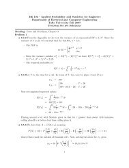
1588 <strong>Creating</strong> <strong>Custom</strong> <strong>3D</strong> <strong>Network</strong> <strong>Visualizations</strong> <strong>with</strong> <strong>OPNET</strong> Modeler® Then the splash screen is replaced by the <strong>OPNET</strong> <strong>3D</strong> <strong>Network</strong> Visualizer main screen.3. Load the monterey OpenFlight file.a. Choose File > Open > Terrain…b. Select the Monterey.mtf and click Open.CONFIDENTIAL – RESTRICTED ACCESS: This information may not be disclosed, copied, or transmitted in any format <strong>with</strong>out the prior written consent of <strong>OPNET</strong> Technologies, Inc.© 2010 <strong>OPNET</strong> Technologies, Inc.Page 3
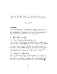
1588 <strong>Creating</strong> <strong>Custom</strong> <strong>3D</strong> <strong>Network</strong> <strong>Visualizations</strong> <strong>with</strong> <strong>OPNET</strong> Modeler® The terrain appears in the viewer.CONFIDENTIAL – RESTRICTED ACCESS: This information may not be disclosed, copied, or transmitted in any format <strong>with</strong>out the prior written consent of <strong>OPNET</strong> Technologies, Inc.© 2010 <strong>OPNET</strong> Technologies, Inc.Page 4
1588 <strong>Creating</strong> <strong>Custom</strong> <strong>3D</strong> <strong>Network</strong> <strong>Visualizations</strong> <strong>with</strong> <strong>OPNET</strong> Modeler®You can use the following keys to move the viewpoint around the terrain.The motions change based on the viewpoint mode.Setting up the <strong>3D</strong> environment4. Launch Modeler.5. Open the o1588 project.6. If it is not the current scenario, switch to lab1. You should see two nodes on a background of elevation lines.CONFIDENTIAL – RESTRICTED ACCESS: This information may not be disclosed, copied, or transmitted in any format <strong>with</strong>out the prior written consent of <strong>OPNET</strong> Technologies, Inc.© 2010 <strong>OPNET</strong> Technologies, Inc.Page 5
1588 <strong>Creating</strong> <strong>Custom</strong> <strong>3D</strong> <strong>Network</strong> <strong>Visualizations</strong> <strong>with</strong> <strong>OPNET</strong> Modeler®The elevation lines are based on the same ‘Monterey’ terrain database as is currently shown in the<strong>OPNET</strong> <strong>3D</strong> <strong>Network</strong> Visualizer. The tmm_data_directory preference is set to that same database sothat the simulation uses matching terrain elevation information.The apis fixed node contains a process model where you will use some of the Ovis APIs to create anentity and some decorations.The bradley mobile node is simply moving around the scenery along a trajectory. This node hasalready been fully written, <strong>with</strong> logic that uses op_ima_obj_pos_get every second to have theSimulation Kernel recompute its position. The code you will write for the apis node is going toassociate an Ovis entity <strong>with</strong> the bradley node. That entity requires explicit position updates fromthe Simulation Kernel to be moved in the <strong>OPNET</strong> <strong>3D</strong> <strong>Network</strong> Visualizer. Such position updateswill occur explicitly in a simulation if the Kernel Procedure op_ima_obj_pos_get is invoked, orimplicitly if the node is involved in some communication. In this case there is no communication sowe need to have the explicit position updates.Too many position updates can affect performance due to the number of updates sent to the <strong>OPNET</strong><strong>3D</strong> <strong>Network</strong> Visualizer. But too few position updates can result in entities appearing to move in avery jerky fashion in the Visualizer. There is no magic answer as to what is a good update frequencyrate; this is something that depends on what else is going on in your simulation.Adding Ovis Code7. Double-click on the apis node to open the o1588_lab1_ovis node model.8. If you do not wish to type the code, change the process model to the reference version.a) Right-click on the ovis module and select Edit Attributes.b) Click on process model attribute value and change it to o1588_lab1_ovis_ref.c) Click OK to save the attribute change.d) Select File > Save.e) Jump to the Viewing the <strong>3D</strong> Items section.CONFIDENTIAL – RESTRICTED ACCESS: This information may not be disclosed, copied, or transmitted in any format <strong>with</strong>out the prior written consent of <strong>OPNET</strong> Technologies, Inc.© 2010 <strong>OPNET</strong> Technologies, Inc.Page 6
1588 <strong>Creating</strong> <strong>Custom</strong> <strong>3D</strong> <strong>Network</strong> <strong>Visualizations</strong> <strong>with</strong> <strong>OPNET</strong> Modeler®9. Double-click on the ovis module in the Node editor to open the o1588_lab1_ovis process model.Some of the code is already in place, and you will take care of filling in the rest.NEXT_SELF(time) is a macro that schedules a self-interrupt time seconds in the future. Thisapproach will be used during the simulation execution to use ODB and prostop to step quicklythrough the visualization code blocks while allowing review of each in the Visualizer. Thevisualization code blocks are going to be located in the Exit Executives of the various states.CONFIDENTIAL – RESTRICTED ACCESS: This information may not be disclosed, copied, or transmitted in any format <strong>with</strong>out the prior written consent of <strong>OPNET</strong> Technologies, Inc.© 2010 <strong>OPNET</strong> Technologies, Inc.Page 7
1588 <strong>Creating</strong> <strong>Custom</strong> <strong>3D</strong> <strong>Network</strong> <strong>Visualizations</strong> <strong>with</strong> <strong>OPNET</strong> Modeler®10. Open the State Variable block to review the pre-defined variables.The very creative entity and decoration names are self-explanatory. Text_percent is going to be usedto position and move the <strong>3D</strong> text decoration along the <strong>3D</strong> line. The various pointers are initialized toOPC_NIL in the init state.11. Double-click on the bottom of the set_cube state to open its Exit Executive.This code block is fully provided as an example for later ones. It creates a yellow cube centered 30meters above the terrain at some arbitrary geodetic location. We use TMM to obtain the terrainelevation at this location and generate a geodetic location 30m higher. The cube has a “radius” of50m so part of the cube will be underground.Next, we want to have an entity representing the bradley mobile node in the <strong>3D</strong> scene.CONFIDENTIAL – RESTRICTED ACCESS: This information may not be disclosed, copied, or transmitted in any format <strong>with</strong>out the prior written consent of <strong>OPNET</strong> Technologies, Inc.© 2010 <strong>OPNET</strong> Technologies, Inc.Page 8
1588 <strong>Creating</strong> <strong>Custom</strong> <strong>3D</strong> <strong>Network</strong> <strong>Visualizations</strong> <strong>with</strong> <strong>OPNET</strong> Modeler®12. Edit the Exit Executives of the set_entity state as follows:Deleted:If you don’t wish to actually type this code, here it is in a form can be copied and pasted into theeditor:entity = Ovis_Entity_Create ("top.Monterrey.bradley", OPC_NIL, OPC_NIL);Ovis_Entity_Animation_Set (entity, OPC_NIL, OvisC_Aggregation_Entity,bradley_dis, OvisC_DIS_Force_Friendly, OvisC_DIS_DR_Static);Ovis_Entity_Animation_Enable (entity);Ovis_Updates_Flush ();This creates an entity associated <strong>with</strong> the top.Monterrey.bradley node, then sets the entityanimation information, such as its DIS type (to have an appropriate <strong>3D</strong> model). Once theinformation is set, we enable the animation and force the information to be sent to the Visualizer.Decoupling the setting from the update allows you to create a large set of entities then perform oneupdate for all of them.13. Click on the File menu. Note that there isn’t a ‘Save’ menu entry, but instead a ‘Commit’ one(associated <strong>with</strong> the Ctrl-S shortcut). Starting in 14.5, saving the changes no longerautomatically close the associated editor. This way you can regularly save your editing whichpushes the data back into the model, and keep editors around to easily copy/paste data. You willstill need to save the whole model from the Process Model editor’s File/Save menu to have yourchanges written to disk.You can use the Close Edit Pad after Saving preference to revert back to the pre-14.5 behaviorof closing when saving.14. Select Commit to push the changes back to the model stored in memory.You can leave the editor open. It will be closed automatically when you close the model.Once the entity is in place, we want to have a translucent sphere displayed around it and movingalong <strong>with</strong> it. This is convenient if you intend to look at the <strong>3D</strong> scene from far away where theentities might not be visible anymore.15. Edit the Exit Executive of the set_sphere state as follows:Formatted: Bullets and NumberingOvis_<strong>3D</strong>_Position_Entity_Set (&pos, entity);CONFIDENTIAL – RESTRICTED ACCESS: This information may not be disclosed, copied, or transmitted in any format <strong>with</strong>out the prior written consent of <strong>OPNET</strong> Technologies, Inc.© 2010 <strong>OPNET</strong> Technologies, Inc.Page 9
1588 <strong>Creating</strong> <strong>Custom</strong> <strong>3D</strong> <strong>Network</strong> <strong>Visualizations</strong> <strong>with</strong> <strong>OPNET</strong> Modeler®sphere = Ovis_Decoration_<strong>3D</strong>_Sphere_Create (pos, 20.0, 20.0, 20.0,blue, OvisC_True, OPC_NIL, OPC_NIL, OPC_NIL);Ovis_Decoration_Transparency_Set (sphere, 50);This sets a position as “relative to entity”, creates a blue sphere using that position (20m radius) andchanges the transparency to 50% level.16. Press Ctrl-S to save changes.Next, let’s have a red dashed line stretching between the blue sphere and the yellow cube createdpreviously. This line will stretch and shrink as the entity moves around the scenery.17. Edit the Exit Executive of the set_line state as follows:Formatted: Bullets and NumberingOvis_<strong>3D</strong>_Position_Decoration_Set (&from, sphere, 0);Ovis_<strong>3D</strong>_Position_Decoration_Set (&to, cube, 0);line = Ovis_Decoration_<strong>3D</strong>_Line_Create (from, to, red,5, OPC_NIL, OPC_NIL, OPC_NIL);Ovis_Shape_Pattern_Set (line, 0x99999999);The 3 rd argument of Ovis_<strong>3D</strong>_Position_Decoration_Set does not apply in this case because sphereand cube have a single position. It will be used later on as we position something along the linewhich has two endpoints.The pattern value is a 32 bit mask that repeats along the line. The line will show where there are 1sin the mask, and not where there are 0s.18. Press Ctrl-S to save changes.Finally, let’s place some text on the line. That text will later move along the line.19. Edit the Exit Executive of the set_text state as followsFormatted: Bullets and NumberingDeleted:Ovis_<strong>3D</strong>_Position_Decoration_Set (&pos, line, text_percent);text = Ovis_Decoration_<strong>3D</strong>_Text_Create ("At 1%", pos, black,OPC_NIL, OPC_NIL, OPC_NIL);The 3 rd argument of Ovis_<strong>3D</strong>_Position_Decoration_Set indicates a percentage from the “start” of thedecoration, i.e., the “from” location for <strong>3D</strong> lines or cylinders.CONFIDENTIAL – RESTRICTED ACCESS: This information may not be disclosed, copied, or transmitted in any format <strong>with</strong>out the prior written consent of <strong>OPNET</strong> Technologies, Inc.© 2010 <strong>OPNET</strong> Technologies, Inc.Page 10
1588 <strong>Creating</strong> <strong>Custom</strong> <strong>3D</strong> <strong>Network</strong> <strong>Visualizations</strong> <strong>with</strong> <strong>OPNET</strong> Modeler®20. Press Ctrl-S to save changes.To move the text along the line, we need to change that percentage. We will also change the text’sstring to indicate the percentage value.21. Edit the Exit Executive of the move_text state as follows:Formatted: Bullets and NumberingOvis_Text_String_Set (text, text_str);Ovis_<strong>3D</strong>_Position_Decoration_Set (&pos, line, text_percent);Ovis_<strong>3D</strong>_Text_Position_Set (text, pos);22. Press Ctrl-S to save changes.23. Compile the process model to make sure all your changes are valid. If you encountercompilation errors, double-check the changes you made against this document.24. Close the Process and Node editors.Viewing the <strong>3D</strong> items25. Click on the o1588 Project window.Deleted:Formatted: Bullets and NumberingFormatted: Bullets and Numbering26. Click on the Configure/Run Discrete Event Simulation (DES) toolbar button ( ).CONFIDENTIAL – RESTRICTED ACCESS: This information may not be disclosed, copied, or transmitted in any format <strong>with</strong>out the prior written consent of <strong>OPNET</strong> Technologies, Inc.© 2010 <strong>OPNET</strong> Technologies, Inc.Page 11
1588 <strong>Creating</strong> <strong>Custom</strong> <strong>3D</strong> <strong>Network</strong> <strong>Visualizations</strong> <strong>with</strong> <strong>OPNET</strong> Modeler®27. Review the settings for this execution.a) TMM is enabled and set to use the same Monterey OpenFlight database as was loaded in the<strong>OPNET</strong> <strong>3D</strong> <strong>Network</strong> Visualizer.b) <strong>3D</strong>NV is enabled. The Ovis APIs are not going to be recorded. Instead this simulation willsend its Ovis changes directly to the <strong>OPNET</strong> <strong>3D</strong> <strong>Network</strong> Visualizer. Also, because allentities are created explicitly, the Mapping library has been set to NONE to avoid invoking itunnecessarily.CONFIDENTIAL – RESTRICTED ACCESS: This information may not be disclosed, copied, or transmitted in any format <strong>with</strong>out the prior written consent of <strong>OPNET</strong> Technologies, Inc.© 2010 <strong>OPNET</strong> Technologies, Inc.Page 12
1588 <strong>Creating</strong> <strong>Custom</strong> <strong>3D</strong> <strong>Network</strong> <strong>Visualizations</strong> <strong>with</strong> <strong>OPNET</strong> Modeler®c) The <strong>OPNET</strong> debugger is enabled. You will use it to step through the execution to reviewthings at your pace.Formatted: Bullets and NumberingCONFIDENTIAL – RESTRICTED ACCESS: This information may not be disclosed, copied, or transmitted in any format <strong>with</strong>out the prior written consent of <strong>OPNET</strong> Technologies, Inc.© 2010 <strong>OPNET</strong> Technologies, Inc.Page 13
1588 <strong>Creating</strong> <strong>Custom</strong> <strong>3D</strong> <strong>Network</strong> <strong>Visualizations</strong> <strong>with</strong> <strong>OPNET</strong> Modeler®28. Click on the Run button. You should see the Simulation Execution dialog box showing the Console <strong>with</strong> the ODB>prompt.29. Click the Next buttonFormatted: Bullets and NumberingCONFIDENTIAL – RESTRICTED ACCESS: This information may not be disclosed, copied, or transmitted in any format <strong>with</strong>out the prior written consent of <strong>OPNET</strong> Technologies, Inc.© 2010 <strong>OPNET</strong> Technologies, Inc.Page 14
1588 <strong>Creating</strong> <strong>Custom</strong> <strong>3D</strong> <strong>Network</strong> <strong>Visualizations</strong> <strong>with</strong> <strong>OPNET</strong> Modeler® A message that the configuration file for <strong>3D</strong>NV communications is being loaded shouldappear indicating that the simulation is joining an HLA federation to be able to communicate<strong>with</strong> the <strong>OPNET</strong> <strong>3D</strong> <strong>Network</strong> Visualizer. There might also be some messages that aregenerated while a terrain is being loaded. These can be ignored.We are only concerned <strong>with</strong> the activities taking place in the o1588_lab1_ovis process instance.30. Type promap all in the ODB> text field The list of active process appears in the console. The one of interest is process ID 1.Formatted: Bullets and Numbering31. Type prostop 1 then protrace 1.32. Click Continue. This executes the initialization of the mobile node and stops at the initializationof the ovis process model.33. Click Continue. This displays the initialization code and stops the execution at the next stateset_cube.Formatted: Bullets and NumberingCONFIDENTIAL – RESTRICTED ACCESS: This information may not be disclosed, copied, or transmitted in any format <strong>with</strong>out the prior written consent of <strong>OPNET</strong> Technologies, Inc.© 2010 <strong>OPNET</strong> Technologies, Inc.Page 15
1588 <strong>Creating</strong> <strong>Custom</strong> <strong>3D</strong> <strong>Network</strong> <strong>Visualizations</strong> <strong>with</strong> <strong>OPNET</strong> Modeler®Formatted: Bullets and NumberingCONFIDENTIAL – RESTRICTED ACCESS: This information may not be disclosed, copied, or transmitted in any format <strong>with</strong>out the prior written consent of <strong>OPNET</strong> Technologies, Inc.© 2010 <strong>OPNET</strong> Technologies, Inc.Page 16
1588 <strong>Creating</strong> <strong>Custom</strong> <strong>3D</strong> <strong>Network</strong> <strong>Visualizations</strong> <strong>with</strong> <strong>OPNET</strong> Modeler®34. Click Continue to execute the set_cube state and stop the simulation once it is ready to executethe set_entity state.35. Click on the <strong>OPNET</strong> <strong>3D</strong> <strong>Network</strong> Visualizer window to bring it in focus.Formatted: Bullets and NumberingCONFIDENTIAL – RESTRICTED ACCESS: This information may not be disclosed, copied, or transmitted in any format <strong>with</strong>out the prior written consent of <strong>OPNET</strong> Technologies, Inc.© 2010 <strong>OPNET</strong> Technologies, Inc.Page 17
1588 <strong>Creating</strong> <strong>Custom</strong> <strong>3D</strong> <strong>Network</strong> <strong>Visualizations</strong> <strong>with</strong> <strong>OPNET</strong> Modeler®36. Select View > Observer Info PanelObserver Info Panel displays location and orientation information for the currently loaded terrain.37. Change the Filter in Objects List Panel to Remote Graphics38. If you have previously moved around the viewpoint, click anywhere on the terrain and then pressthe spacebar to return to initial state so that the viewpoint looks as below, <strong>with</strong> a ‘Heading’ valueof 0.CONFIDENTIAL – RESTRICTED ACCESS: This information may not be disclosed, copied, or transmitted in any format <strong>with</strong>out the prior written consent of <strong>OPNET</strong> Technologies, Inc.© 2010 <strong>OPNET</strong> Technologies, Inc.Page 18
1588 <strong>Creating</strong> <strong>Custom</strong> <strong>3D</strong> <strong>Network</strong> <strong>Visualizations</strong> <strong>with</strong> <strong>OPNET</strong> Modeler®Formatted: Bullets and NumberingCONFIDENTIAL – RESTRICTED ACCESS: This information may not be disclosed, copied, or transmitted in any format <strong>with</strong>out the prior written consent of <strong>OPNET</strong> Technologies, Inc.© 2010 <strong>OPNET</strong> Technologies, Inc.Page 19
1588 <strong>Creating</strong> <strong>Custom</strong> <strong>3D</strong> <strong>Network</strong> <strong>Visualizations</strong> <strong>with</strong> <strong>OPNET</strong> Modeler®39. Use the ‘s’ key to move the viewpoint back until ‘Y’ is around 87,000 in Observer Info Panel40. Use the ‘d’ key to move the viewpoint to the right until you see a yellow cube in the distance.CONFIDENTIAL – RESTRICTED ACCESS: This information may not be disclosed, copied, or transmitted in any format <strong>with</strong>out the prior written consent of <strong>OPNET</strong> Technologies, Inc.© 2010 <strong>OPNET</strong> Technologies, Inc.Page 20
1588 <strong>Creating</strong> <strong>Custom</strong> <strong>3D</strong> <strong>Network</strong> <strong>Visualizations</strong> <strong>with</strong> <strong>OPNET</strong> Modeler®Formatted: Bullets and NumberingCONFIDENTIAL – RESTRICTED ACCESS: This information may not be disclosed, copied, or transmitted in any format <strong>with</strong>out the prior written consent of <strong>OPNET</strong> Technologies, Inc.© 2010 <strong>OPNET</strong> Technologies, Inc.Page 21
1588 <strong>Creating</strong> <strong>Custom</strong> <strong>3D</strong> <strong>Network</strong> <strong>Visualizations</strong> <strong>with</strong> <strong>OPNET</strong> Modeler®41. Back in the Simulation Console, click on Continue. This should create and animate an Ovis Entity.42. Back in the <strong>OPNET</strong> <strong>3D</strong> <strong>Network</strong> Visualizer, there should now be a light blue circle near wherethe yellow cube is located. This indicates a friendly entity.Formatted: Bullets and NumberingFormatted: Bullets and NumberingCONFIDENTIAL – RESTRICTED ACCESS: This information may not be disclosed, copied, or transmitted in any format <strong>with</strong>out the prior written consent of <strong>OPNET</strong> Technologies, Inc.© 2010 <strong>OPNET</strong> Technologies, Inc.Page 22
1588 <strong>Creating</strong> <strong>Custom</strong> <strong>3D</strong> <strong>Network</strong> <strong>Visualizations</strong> <strong>with</strong> <strong>OPNET</strong> Modeler®43. Move the cursor close to that blue circle until an Entity Label appears, <strong>with</strong> the entity name(bradley), its DIS type, and various other pieces of information.CONFIDENTIAL – RESTRICTED ACCESS: This information may not be disclosed, copied, or transmitted in any format <strong>with</strong>out the prior written consent of <strong>OPNET</strong> Technologies, Inc.© 2010 <strong>OPNET</strong> Technologies, Inc.Page 23
1588 <strong>Creating</strong> <strong>Custom</strong> <strong>3D</strong> <strong>Network</strong> <strong>Visualizations</strong> <strong>with</strong> <strong>OPNET</strong> Modeler®44. Change the Filter in Objects List Panel to EntitiesFormatted: Bullets and Numbering45. Right-click on the entity and select Attach Tether.CONFIDENTIAL – RESTRICTED ACCESS: This information may not be disclosed, copied, or transmitted in any format <strong>with</strong>out the prior written consent of <strong>OPNET</strong> Technologies, Inc.© 2010 <strong>OPNET</strong> Technologies, Inc.Page 24
1588 <strong>Creating</strong> <strong>Custom</strong> <strong>3D</strong> <strong>Network</strong> <strong>Visualizations</strong> <strong>with</strong> <strong>OPNET</strong> Modeler® The viewpoint changes to close to the entity.Formatted: Bullets and NumberingCONFIDENTIAL – RESTRICTED ACCESS: This information may not be disclosed, copied, or transmitted in any format <strong>with</strong>out the prior written consent of <strong>OPNET</strong> Technologies, Inc.© 2010 <strong>OPNET</strong> Technologies, Inc.Page 25
1588 <strong>Creating</strong> <strong>Custom</strong> <strong>3D</strong> <strong>Network</strong> <strong>Visualizations</strong> <strong>with</strong> <strong>OPNET</strong> Modeler®46. Press the left –arrow until you see yellow cube again. You might also need to move viewpointdown (using the down-arrow)Formatted: Bullets and NumberingCONFIDENTIAL – RESTRICTED ACCESS: This information may not be disclosed, copied, or transmitted in any format <strong>with</strong>out the prior written consent of <strong>OPNET</strong> Technologies, Inc.© 2010 <strong>OPNET</strong> Technologies, Inc.Page 26
1588 <strong>Creating</strong> <strong>Custom</strong> <strong>3D</strong> <strong>Network</strong> <strong>Visualizations</strong> <strong>with</strong> <strong>OPNET</strong> Modeler®47. Back in the Simulation Console, click Continue. This should create a translucent sphere around the entity.Deleted:CONFIDENTIAL – RESTRICTED ACCESS: This information may not be disclosed, copied, or transmitted in any format <strong>with</strong>out the prior written consent of <strong>OPNET</strong> Technologies, Inc.© 2010 <strong>OPNET</strong> Technologies, Inc.Page 27
1588 <strong>Creating</strong> <strong>Custom</strong> <strong>3D</strong> <strong>Network</strong> <strong>Visualizations</strong> <strong>with</strong> <strong>OPNET</strong> Modeler®Formatted: Bullets and NumberingCONFIDENTIAL – RESTRICTED ACCESS: This information may not be disclosed, copied, or transmitted in any format <strong>with</strong>out the prior written consent of <strong>OPNET</strong> Technologies, Inc.© 2010 <strong>OPNET</strong> Technologies, Inc.Page 28
1588 <strong>Creating</strong> <strong>Custom</strong> <strong>3D</strong> <strong>Network</strong> <strong>Visualizations</strong> <strong>with</strong> <strong>OPNET</strong> Modeler®48. Zoom out a bit to view more of the sphere above ground and the yellow decoration.49. Back in the Simulation Console, click Continue.Formatted: Bullets and NumberingCONFIDENTIAL – RESTRICTED ACCESS: This information may not be disclosed, copied, or transmitted in any format <strong>with</strong>out the prior written consent of <strong>OPNET</strong> Technologies, Inc.© 2010 <strong>OPNET</strong> Technologies, Inc.Page 29
1588 <strong>Creating</strong> <strong>Custom</strong> <strong>3D</strong> <strong>Network</strong> <strong>Visualizations</strong> <strong>with</strong> <strong>OPNET</strong> Modeler® This should create a dashed red line between the entity and the yellow decoration.CONFIDENTIAL – RESTRICTED ACCESS: This information may not be disclosed, copied, or transmitted in any format <strong>with</strong>out the prior written consent of <strong>OPNET</strong> Technologies, Inc.© 2010 <strong>OPNET</strong> Technologies, Inc.Page 30
1588 <strong>Creating</strong> <strong>Custom</strong> <strong>3D</strong> <strong>Network</strong> <strong>Visualizations</strong> <strong>with</strong> <strong>OPNET</strong> Modeler®50. Back in the Simulation Console, click Continue. This should create some black text “At 1%” positioned near the Bradley, on the dashed redline and also move the Bradley.Formatted: Bullets and NumberingDeleted: create a dashed red linebetween the entity and the yellowdecorationDeleted: .CONFIDENTIAL – RESTRICTED ACCESS: This information may not be disclosed, copied, or transmitted in any format <strong>with</strong>out the prior written consent of <strong>OPNET</strong> Technologies, Inc.© 2010 <strong>OPNET</strong> Technologies, Inc.Page 31
1588 <strong>Creating</strong> <strong>Custom</strong> <strong>3D</strong> <strong>Network</strong> <strong>Visualizations</strong> <strong>with</strong> <strong>OPNET</strong> Modeler® In the <strong>OPNET</strong> <strong>3D</strong> <strong>Network</strong> Visualizer, the viewpoint suddenly moves. In fact, the entity ismoving because the simulation just advanced by 10s, checking the node position everysecond and automatically updating that position in the Visualizer. Next to the entity, butactually positioned on the red line, is At 1% in black. The line will stretch between themoving entity and the fixed yellow decoration as needed.At this point the simulation has reached the phase where the ‘ovis’ process model will loop every3 seconds of simulation time and move the text position. Every time you click on Continue, thesimulation time will advance by 3s, the entity will move along its trajectory by 3s, and the textwill be moved by one percent of the line length. Zoom out if the text disappears from view.Formatted: Bullets and NumberingCONFIDENTIAL – RESTRICTED ACCESS: This information may not be disclosed, copied, or transmitted in any format <strong>with</strong>out the prior written consent of <strong>OPNET</strong> Technologies, Inc.© 2010 <strong>OPNET</strong> Technologies, Inc.Page 32
1588 <strong>Creating</strong> <strong>Custom</strong> <strong>3D</strong> <strong>Network</strong> <strong>Visualizations</strong> <strong>with</strong> <strong>OPNET</strong> Modeler®51. When the text says At 3%, it looks like the red line is gone:In fact, it’s simply that the line is underground at this point because of the lay of the land.52. Select Settings > Wireframe Rendering The display changes to a wireframe representation of the various elements. The terrain ismuch harder to see but you can now see that the red line reappears.Formatted: Bullets and NumberingCONFIDENTIAL – RESTRICTED ACCESS: This information may not be disclosed, copied, or transmitted in any format <strong>with</strong>out the prior written consent of <strong>OPNET</strong> Technologies, Inc.© 2010 <strong>OPNET</strong> Technologies, Inc.Page 33
1588 <strong>Creating</strong> <strong>Custom</strong> <strong>3D</strong> <strong>Network</strong> <strong>Visualizations</strong> <strong>with</strong> <strong>OPNET</strong> Modeler®53. Select Settings > Wireframe Rendering to reset the view to its normal look, then continue toadvance the simulation by clicking on Continue in the Simulation Console.54. When you have seen enough, type quit in the Simulation Console. The simulation terminates, and the entity and decorations disappear in the <strong>OPNET</strong> <strong>3D</strong><strong>Network</strong> Visualizer55. Close the Simulation window and the project.Formatted: Bullets and NumberingFormatted: Bullets and NumberingConclusionYou used several Ovis APIs to create a simple <strong>3D</strong> animation and review it in the <strong>OPNET</strong> <strong>3D</strong><strong>Network</strong> Visualizer. As you can see, it isn’t hard to generate a <strong>3D</strong> scene from a simulation. Thehard part comes from figuring out which <strong>3D</strong> visualizations are appropriate for a given protocol.END OF LAB 1CONFIDENTIAL – RESTRICTED ACCESS: This information may not be disclosed, copied, or transmitted in any format <strong>with</strong>out the prior written consent of <strong>OPNET</strong> Technologies, Inc.© 2010 <strong>OPNET</strong> Technologies, Inc.Page 34
1588 <strong>Creating</strong> <strong>Custom</strong> <strong>3D</strong> <strong>Network</strong> <strong>Visualizations</strong> <strong>with</strong> <strong>OPNET</strong> Modeler®Lab 2: Using Ovis Communication CallbacksOverviewYou want to see a <strong>3D</strong> visualization of the packet exchange for application traffic in a Wireless LANusing MANET. You want to see the actual route that traffic takes in the wireless network from clientto server and also the nodes affected by radio broadcast—even if they are not the intended recipientsof the data.But you do not want to modify the code of the pipeline stages used by the Wireless LAN transmitterand receiver modules, since you want to ensure that the <strong>3D</strong> visualization code can be easily reused<strong>with</strong> future releases of these pipeline stages. You will use the Ovis communication callbackinfrastructure to integrate <strong>with</strong> existing pipeline stages used in the Wireless LAN to peek intopackets and provide appropriate visualizations.Objectives• Review provided Ovis communication code.• Extend communication code <strong>with</strong> appropriate Ovis calls to generate <strong>3D</strong> lines based on traffictype and packet destination.Use the Ovis Communication Callback mechanism to visualize application traffic between client andserver using WLAN and MANET.InstructionsReviewing the network model1. If it is not already open, launch Modeler.2. Open the o1588 project.Formatted: Bullets and NumberingCONFIDENTIAL – RESTRICTED ACCESS: This information may not be disclosed, copied, or transmitted in any format <strong>with</strong>out the prior written consent of <strong>OPNET</strong> Technologies, Inc.© 2010 <strong>OPNET</strong> Technologies, Inc.Page 35
1588 <strong>Creating</strong> <strong>Custom</strong> <strong>3D</strong> <strong>Network</strong> <strong>Visualizations</strong> <strong>with</strong> <strong>OPNET</strong> Modeler®3. Switch to the lab2 scenario. You see a set of wireless nodes, several configuration objects, and elevation lines.Deleted:All the wireless nodes are using MANET over Wireless LAN. The nodes come in three flavors:• Three servers, each one servicing one type of application: Email, FTP, and HTTP.• Three clients, each one using one type of application.• The rest of the nodes are simply there to provide connectivity.This configuration is simplified for clearer visualizations in this lab. In a more realistic scenario,all nodes could be clients of multiple application services, and servers could service multipleapplication types.Some of the nodes have associated trajectories shown as lines <strong>with</strong> blue arrows.CONFIDENTIAL – RESTRICTED ACCESS: This information may not be disclosed, copied, or transmitted in any format <strong>with</strong>out the prior written consent of <strong>OPNET</strong> Technologies, Inc.© 2010 <strong>OPNET</strong> Technologies, Inc.Page 36
1588 <strong>Creating</strong> <strong>Custom</strong> <strong>3D</strong> <strong>Network</strong> <strong>Visualizations</strong> <strong>with</strong> <strong>OPNET</strong> Modeler®The configuration nodes are• App Config: Definition of the applications available in this network• Profile Config: Definition of the client profiles used in this network• Rx Group Config: Causes every receiver group to be recomputed every 10s. The receivergroup of a transmitter channel includes all receivers <strong>with</strong>in 1km of thetransmitting node.• Lab2 Visualization: Contains the Ovis code to implement the route visualization. You willfill in missing sections of this code to complete the implementation.Note 1: If you wish, you can skip the programming and simulation running, and jump directly tothe Setting up <strong>OPNET</strong> <strong>3D</strong> <strong>Network</strong> Visualizer section.Note 2: This lab is going to use three different colors to represent the path of the threeapplications. The default colors are yellow, red, and blue.If you prefer different colors, you can modify these as follows:a. Right-click on the Lab2 <strong>Visualizations</strong> node and select Edit Attributes.b. Click on the + next to the Color attribute name.Deleted: theDeleted: Sim Time: Display thecurrent simulation time as 2D text in the<strong>3D</strong> <strong>Network</strong> VisualizerDeleted: thisc. Click on the Value field for any of the application type you wish to change and pick anappropriate color.d. Click OK.CONFIDENTIAL – RESTRICTED ACCESS: This information may not be disclosed, copied, or transmitted in any format <strong>with</strong>out the prior written consent of <strong>OPNET</strong> Technologies, Inc.© 2010 <strong>OPNET</strong> Technologies, Inc.Page 37
1588 <strong>Creating</strong> <strong>Custom</strong> <strong>3D</strong> <strong>Network</strong> <strong>Visualizations</strong> <strong>with</strong> <strong>OPNET</strong> Modeler®Reviewing the Ovis process model4. Double-click on the Lab2 <strong>Visualizations</strong> node to view its associated node model.5. Double-click on the mod processor to view its associated process model.Formatted: Bullets and NumberingThe ‘delay’ state simply schedules an interrupt at 0.1 second to ensure that all the protocolinitializations have been performed, in particular the auto-assignment of MAC addresses.The ‘init’ state assigns a set of callbacks to wireless transmitter channels. These callbacks will beinvoked by the simulation kernel during packet transmission.6. Double-click on the Enter Executive area of the init state to view the initialization code.The initialization takes care of the following operations:a) Retrieve the delay and color attribute values that define the configuration options available inthe “Lab2 <strong>Visualizations</strong>” node. These are model attributes defined by this process modeland help the user customize the way visualizations are going to be displayed.b) Create the set of Ovis layers to control what to show in the <strong>OPNET</strong> <strong>3D</strong> <strong>Network</strong> Visualizer.c) Assign the Ovis communication callbacks to each wireless transmitter channel.d) Attach a large translucent sphere or cube to each node to allow better viewing from afar.7. Close the Enter Executive editor when done.Formatted: Bullets and NumberingFormatted: Bullets and Numbering8. Click on the Function Block toolbar button ( ) to review the communication callbacks.Only the callbacks used in this lab have been defined. The other entries are nil pointers.The main callbacks of interest are:CONFIDENTIAL – RESTRICTED ACCESS: This information may not be disclosed, copied, or transmitted in any format <strong>with</strong>out the prior written consent of <strong>OPNET</strong> Technologies, Inc.© 2010 <strong>OPNET</strong> Technologies, Inc.Page 38
1588 <strong>Creating</strong> <strong>Custom</strong> <strong>3D</strong> <strong>Network</strong> <strong>Visualizations</strong> <strong>with</strong> <strong>OPNET</strong> Modeler®a) Receiver init (rx_init): Obtain the MAC address of the WLAN layer. This is used duringreception to check if a packet is destined for this node or just something that wasreceived due to the broadcast. The MAC address is stored as state associated <strong>with</strong> thereceiver for later use during receptions.b) Transmission start (xmit_start): Checks if the packet is a WLAN data packet and if thecontent is a bit range from known application traffic. If that’s the case, associate astate <strong>with</strong> the transmission <strong>with</strong> appropriate information relative to the packet:• Destination MAC address• Application color• Application Ovis layer• <strong>3D</strong> offset: This ensures that lines representing multiple active applications are notobscuring each other by drawing them <strong>with</strong> slight offsets depending on theapplication type.c) Reception start (rcpt_start): If the transmission has an associated state, use that and thereception’s receiver’s state to create an appropriate line. Each line stays visible forsome simulation time (controlled via attributes of the process model that appear asconfiguration attributes of the visualization configuration node) after which asimulation event invokes a function that destroys the line.A small portion of the reception start code is missing and awaits your input to complete.9. Scroll down to the end of the o1588_lab2_rcpt_start function (line 241) and fill in the missingpart.Deleted:Deleted:Deleted:Formatted: Bullets and NumberingCONFIDENTIAL – RESTRICTED ACCESS: This information may not be disclosed, copied, or transmitted in any format <strong>with</strong>out the prior written consent of <strong>OPNET</strong> Technologies, Inc.© 2010 <strong>OPNET</strong> Technologies, Inc.Page 39
1588 <strong>Creating</strong> <strong>Custom</strong> <strong>3D</strong> <strong>Network</strong> <strong>Visualizations</strong> <strong>with</strong> <strong>OPNET</strong> Modeler®CONFIDENTIAL – RESTRICTED ACCESS: This information may not be disclosed, copied, or transmitted in any format <strong>with</strong>out the prior written consent of <strong>OPNET</strong> Technologies, Inc.© 2010 <strong>OPNET</strong> Technologies, Inc.Page 40
1588 <strong>Creating</strong> <strong>Custom</strong> <strong>3D</strong> <strong>Network</strong> <strong>Visualizations</strong> <strong>with</strong> <strong>OPNET</strong> Modeler®You will need to use the following Ovis APIs and Kernel Procedures:• Ovis_Decoration_Transparency_Set• Ovis_<strong>3D</strong>_Decoration_Offset_Set• op_intrpt_schedule_call10. When you are done coding, save the function block (which will not close) and compile theprocess model (which should succeed).11. Close the Process Model and Node Model editors.Recording Visualization of Wireless LAN Paths in simulation12. Return to the Project Editor in Modeler.13. Click on the Configure/Run Discrete Event Simulation (DES) toolbar button . The Configure/Run DES:o1588-lab2 dialog box appears.14. Expand the Outputs and Animation treeview elements.15. Click on the <strong>3D</strong> tree node.Formatted: Bullets and NumberingFormatted: Bullets and NumberingFormatted: Bullets and Numbering16. Check thata. Use <strong>3D</strong>NV Module is enabled.b. Record history in file is enabled.Formatted: Bullets and NumberingCONFIDENTIAL – RESTRICTED ACCESS: This information may not be disclosed, copied, or transmitted in any format <strong>with</strong>out the prior written consent of <strong>OPNET</strong> Technologies, Inc.© 2010 <strong>OPNET</strong> Technologies, Inc.Page 41
1588 <strong>Creating</strong> <strong>Custom</strong> <strong>3D</strong> <strong>Network</strong> <strong>Visualizations</strong> <strong>with</strong> <strong>OPNET</strong> Modeler®c. Live output via <strong>3D</strong>NV Communication is NOT enabled: You will view the visualizationafter the simulation completes.Note that you could perfectly run this simulation <strong>with</strong> a live output, as you did in Lab 1. Recordingfor playback and live visualization are not mutually exclusive. We are using the recording this timeto illustrate its use.17. Click Run. The Simulation Progress dialog box appears.Formatted: Bullets and NumberingCONFIDENTIAL – RESTRICTED ACCESS: This information may not be disclosed, copied, or transmitted in any format <strong>with</strong>out the prior written consent of <strong>OPNET</strong> Technologies, Inc.© 2010 <strong>OPNET</strong> Technologies, Inc.Page 42
1588 <strong>Creating</strong> <strong>Custom</strong> <strong>3D</strong> <strong>Network</strong> <strong>Visualizations</strong> <strong>with</strong> <strong>OPNET</strong> Modeler® The various object files are being compiled. After a short while, the simulation is loadedand executed. This should only take a short time to complete since there is no live <strong>3D</strong>NVcommunication going on.Deleted:18. Once the simulation terminates, Close the Simulation Progress dialog box.Setting up <strong>OPNET</strong> <strong>3D</strong> <strong>Network</strong> Visualizer19. If it is not already running, launch the <strong>3D</strong>NV Communication 3.0.0.20. If it is not already running, launch the <strong>OPNET</strong> <strong>3D</strong> <strong>Network</strong> Visualizer 3.0.0.21. If not already loaded, load the “Monterey” OpenFlight terrain (once again corresponding to theterrain set up in Modeler).a. Choose File > Open > Terrain….b. Select the Monterey.mtf file and click Open.22. Check that Settings > Remote Graphics is enabled to ensure that Ovis decorations appear.23. Load predefined views for this lab.Formatted: Bullets and NumberingFormatted: Bullets and NumberingFormatted: Bullets and NumberingCONFIDENTIAL – RESTRICTED ACCESS: This information may not be disclosed, copied, or transmitted in any format <strong>with</strong>out the prior written consent of <strong>OPNET</strong> Technologies, Inc.© 2010 <strong>OPNET</strong> Technologies, Inc.Page 43
1588 <strong>Creating</strong> <strong>Custom</strong> <strong>3D</strong> <strong>Network</strong> <strong>Visualizations</strong> <strong>with</strong> <strong>OPNET</strong> Modeler®a. In <strong>3D</strong>NV, click on Import and merge views icon (highlighted below) from Observer ViewsPanel.b. In the file chooser, browse to C:\op_models, select 1588_lab2_views.osrx, and click Open.Previously captured views will be loaded in the Observer Views Panel (the lower-left box) inthe <strong>3D</strong> <strong>Network</strong> Visualizer. At this point your <strong>OPNET</strong> <strong>3D</strong> <strong>Network</strong> Visualizer should look as follows: (if you havepreviously moved around the viewpoint or are continuing from Lab1, press spacebar toreset the view).Formatted: Bullets and NumberingCONFIDENTIAL – RESTRICTED ACCESS: This information may not be disclosed, copied, or transmitted in any format <strong>with</strong>out the prior written consent of <strong>OPNET</strong> Technologies, Inc.© 2010 <strong>OPNET</strong> Technologies, Inc.Page 44
1588 <strong>Creating</strong> <strong>Custom</strong> <strong>3D</strong> <strong>Network</strong> <strong>Visualizations</strong> <strong>with</strong> <strong>OPNET</strong> Modeler®Viewing Wireless LAN Paths in simulation24. Return to the Project Editor in Modeler.25. Select <strong>3D</strong>NV > Play <strong>3D</strong>NV History… The Choose <strong>3D</strong>NV history file dialog box appears and shows the file generated for thislab.Formatted: Bullets and NumberingIf you skipped the programming part, select the o1588_lab2_ref file instead.26. Click OK.Formatted: Bullets and NumberingCONFIDENTIAL – RESTRICTED ACCESS: This information may not be disclosed, copied, or transmitted in any format <strong>with</strong>out the prior written consent of <strong>OPNET</strong> Technologies, Inc.© 2010 <strong>OPNET</strong> Technologies, Inc.Page 45
1588 <strong>Creating</strong> <strong>Custom</strong> <strong>3D</strong> <strong>Network</strong> <strong>Visualizations</strong> <strong>with</strong> <strong>OPNET</strong> Modeler® The <strong>3D</strong>NV History dialog box appears, showing the Ovis items defined duringsimulation time 0s.Each entity is shown <strong>with</strong> its name and its Ovis ID (#...).There are no equivalent entities in the <strong>OPNET</strong> <strong>3D</strong> <strong>Network</strong> Visualizer at this point. This is justshowing you the Ovis items that are defined from the history file. Before you enable the RTIrepresentation, let’s advance time a bit to include some additional Ovis items.27. Click in the Current time field and change its value to 1s.28. Hit the Tab key to move the focus to another control.Formatted: Bullets and NumberingCONFIDENTIAL – RESTRICTED ACCESS: This information may not be disclosed, copied, or transmitted in any format <strong>with</strong>out the prior written consent of <strong>OPNET</strong> Technologies, Inc.© 2010 <strong>OPNET</strong> Technologies, Inc.Page 46
1588 <strong>Creating</strong> <strong>Custom</strong> <strong>3D</strong> <strong>Network</strong> <strong>Visualizations</strong> <strong>with</strong> <strong>OPNET</strong> Modeler® The <strong>3D</strong>NV history is read further to cover all the changes between the previous time (0s)and the new time (1s).This covers the creation of a number of decorations located where each entity is placed.Because these decorations are using the entities as position, they are shown as AttachedDecorations under their respective entities.29. Expand the tree next to email_client (#14).Formatted: Bullets and Numbering30. Expand the [Attached Decorations] subtree of email_client (#14).31. Click on the <strong>3D</strong> Sphere (#88) leaf node. Information about the item is displayed on the right.Formatted: Bullets and NumberingDuring the playback, the tree will be updated as entities, decorations, layers, and groups are created,moved, or deleted. Now let’s show these entities and decorations in the <strong>OPNET</strong> <strong>3D</strong> <strong>Network</strong>Visualizer.32. Click on Enable RTI buttonDeleted:Formatted: Bullets and NumberingCONFIDENTIAL – RESTRICTED ACCESS: This information may not be disclosed, copied, or transmitted in any format <strong>with</strong>out the prior written consent of <strong>OPNET</strong> Technologies, Inc.© 2010 <strong>OPNET</strong> Technologies, Inc.Page 47
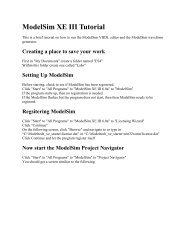
1588 <strong>Creating</strong> <strong>Custom</strong> <strong>3D</strong> <strong>Network</strong> <strong>Visualizations</strong> <strong>with</strong> <strong>OPNET</strong> Modeler® A progress bar appears for establishing the <strong>3D</strong>NV communication, then creating the RTIrepresentations of the enabled items.33. In the <strong>OPNET</strong> <strong>3D</strong> <strong>Network</strong> Visualizer window, click on the Overview_Clients view. The view includes a number of translucent spheres and cubes. These are marking thepositions of the entities.Formatted: Bullets and NumberingThe large colored spheres are the three clients, the large colored cubes are the three servers, andthe other spheres are the relay nodes. If you move the cursor near an entity, you see a popup <strong>with</strong>the name of the entity and the corresponding <strong>OPNET</strong> node.The application traffic is configured for the first minute of simulation specifically to allow areview of each application type individually, followed later by all three together. After a minuteof simulation, application traffic is triggered repeatedly <strong>with</strong> some uniform distributions and thenodes <strong>with</strong> trajectories start moving, providing a more dynamic phase to the simulation.First, let’s review the path for each application type.34. In the <strong>3D</strong>NV History dialog box, set the Current time to 11s then hit Tab.35. Look at the <strong>OPNET</strong> <strong>3D</strong> <strong>Network</strong> Visualizer.Formatted: Bullets and NumberingCONFIDENTIAL – RESTRICTED ACCESS: This information may not be disclosed, copied, or transmitted in any format <strong>with</strong>out the prior written consent of <strong>OPNET</strong> Technologies, Inc.© 2010 <strong>OPNET</strong> Technologies, Inc.Page 48
1588 <strong>Creating</strong> <strong>Custom</strong> <strong>3D</strong> <strong>Network</strong> <strong>Visualizations</strong> <strong>with</strong> <strong>OPNET</strong> Modeler® A set of yellow lines appear between some of the entities, <strong>with</strong> a thicker path between theEmail client and server. Some of the lines are not fully visible as they cut through higherterrain between their endpoints.36. In the <strong>3D</strong>NV History dialog box, set the Current time to 22s, hit Tab, then look at the <strong>OPNET</strong><strong>3D</strong> <strong>Network</strong> Visualizer. The yellow lines disappear and a set of red lines appear to show the FTP data path andother wireless messages.Formatted: Bullets and Numbering37. In the <strong>3D</strong>NV History dialog box, set the Current time to 31s, hit Tab, then look at the <strong>OPNET</strong><strong>3D</strong> <strong>Network</strong> Visualizer.Formatted: Bullets and NumberingCONFIDENTIAL – RESTRICTED ACCESS: This information may not be disclosed, copied, or transmitted in any format <strong>with</strong>out the prior written consent of <strong>OPNET</strong> Technologies, Inc.© 2010 <strong>OPNET</strong> Technologies, Inc.Page 49
1588 <strong>Creating</strong> <strong>Custom</strong> <strong>3D</strong> <strong>Network</strong> <strong>Visualizations</strong> <strong>with</strong> <strong>OPNET</strong> Modeler® The red lines disappear and a set of blue lines appear to show the HTTP data path andother wireless messages.Now let’s view all three together. The email client is going to send an email around 40s, then theHTTP client is going to access a page around 42s, and the ftp client will send a file around 45s.38. In the <strong>3D</strong>NV History dialog box, set the Current time to 44.5s, hit Tab, then look at the<strong>OPNET</strong> <strong>3D</strong> <strong>Network</strong> Visualizer. The existing blue lines disappear, then the three sets of colored lines reappear.Formatted: Bullets and NumberingYou can use the other provided views to look at the network from other vantage points.CONFIDENTIAL – RESTRICTED ACCESS: This information may not be disclosed, copied, or transmitted in any format <strong>with</strong>out the prior written consent of <strong>OPNET</strong> Technologies, Inc.© 2010 <strong>OPNET</strong> Technologies, Inc.Page 50
1588 <strong>Creating</strong> <strong>Custom</strong> <strong>3D</strong> <strong>Network</strong> <strong>Visualizations</strong> <strong>with</strong> <strong>OPNET</strong> Modeler®a. The Overview_Servers view:b. LookingDown puts the viewpoint high above to match the layout in the Project Editor:CONFIDENTIAL – RESTRICTED ACCESS: This information may not be disclosed, copied, or transmitted in any format <strong>with</strong>out the prior written consent of <strong>OPNET</strong> Technologies, Inc.© 2010 <strong>OPNET</strong> Technologies, Inc.Page 51
1588 <strong>Creating</strong> <strong>Custom</strong> <strong>3D</strong> <strong>Network</strong> <strong>Visualizations</strong> <strong>with</strong> <strong>OPNET</strong> Modeler®c. Click on Overview_Clients to return to the original viewpoint.Starting at 1 minute into the simulation, some of the nodes are going to move along theirtrajectories and the 3 client nodes are going to generate traffic on a regular basis. As nodes move,some of the routing is going to adjust, so let’s view that.Note how the data path is affected by terrain features and can thus be quite convoluted. Theinitial state of the simulation had a convoluted path due to terrain obstructions. As some nodesare moved, more “natural” paths are appearing.39. In the <strong>3D</strong>NV History dialog box, click on the Play button ( ) and look at the <strong>OPNET</strong> <strong>3D</strong><strong>Network</strong> Visualizer window. The playback will automatically stop when it reaches the end of thehistory file.Note that if you see something of interest, you can always pause the playback.40. When you are done, close the <strong>3D</strong>NV History dialog box. This automatically destroys the entitiesand decorations shown in the Visualizer.ConclusionYou visualized the flow of data between clients and servers along an established route, as well as theside effects of broadcast packets received by nearby nodes that were not intended recipients of thedata. Further, you visualized distinct application types by coloring lines associated <strong>with</strong> their datatransfer using different colors.Viewing this information in <strong>3D</strong> can help explain how the combination of terrain and mobility resultsin unusual routes being formed.And because of the modular nature of the Ovis communication pipeline infrastructure, the animationprocess model can be added to any Wireless LAN network <strong>with</strong>out interference <strong>with</strong> the providedpipeline stages.Formatted: Bullets and NumberingFormatted: Bullets and NumberingDeleted: thatDeleted: areEND OF LAB 2CONFIDENTIAL – RESTRICTED ACCESS: This information may not be disclosed, copied, or transmitted in any format <strong>with</strong>out the prior written consent of <strong>OPNET</strong> Technologies, Inc.© 2010 <strong>OPNET</strong> Technologies, Inc.Page 52