Ground Fault Monitor RCMA470
Ground Fault Monitor RCMA470
Ground Fault Monitor RCMA470
Create successful ePaper yourself
Turn your PDF publications into a flip-book with our unique Google optimized e-Paper software.
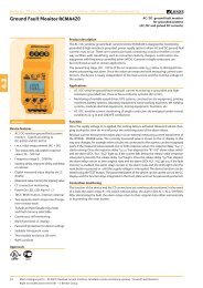
Bender Inc - 700 Fox Chase - Coatesville, PA 19320 - Toll-free: 1-800-356-4266 - Web: www.bender.org<strong>Ground</strong> <strong>Fault</strong> <strong>Monitor</strong> <strong>RCMA470</strong>AC / DC <strong>Ground</strong> <strong>Fault</strong> Current <strong>Monitor</strong>for grounded systems(AC, DC and pulsed DC currents)4.2<strong>RCMA470</strong>LYDevice Features• External measuring current transformer• Two separately adjustable response values,Alarm I Δn1: 30 mA…3 A (0…150 Hz)prewarning I Δn2: 50%/100% of IΔn1• Adjustable response delay 0…10 s(prewarning 0 / 1 s)• Two separate alarm relays with onechangeover contact each• Failsafe or Non-failsafe relay mode• <strong>Fault</strong> memory• Combined TEST and RESET button• Connection external TEST and RESETbutton• LED bar graph indicator I Δn 0…100 %• Connection external measuring instrumentI Δn 0…100 %• CT connection monitoring• Sealable transparent cover• Separate supply voltage• Type B acc. to IEC 60755ApprovalsProduct DescriptionThe AC / DC sensitive ground fault current monitor <strong>RCMA470</strong>LY is designed for monitoringgrounded & high-resistance grounded power supply systems where AC and DC ground faultcurrents may occur. These are in particular loads containing six-pulse rectifiers or one wayrectifiers with smoothing, such as converters, battery chargers, construction site equipmentwith frequency-controlled drives (VFDs).The prewarning stage (50 % of the set response value I Δn1) allow to distinguish betweenprewarning and alarm. Since the values are measured with measuring current transformers,the device is nearly independent of the load current and the nominal voltage of the system.The device can also be used for busbar systems.Application• AC / DC sensitive residual current monitoringin grounded two, three or fourconductor systems.• AC / DC sensitive current monitoring ofsingle conductors de-energized undernormal conditions (e. g. N and PE conductors).• Variable-speed drives• Uninterruptible power supply systems (UPS)• Construction site equipment• Mining equipment• Battery systems• Computer tomographs• Laboratory equipment• Photovoltaic systems• Furniture industry• Sewage worksFunctionResidual current monitoring takes place via an external measuring current transformer. Whenthe residual current respectively the current exceeds the set response value, the alarm LEDlights and the associated alarm relay switches when the response delay has elapsed.The alarm messages are stored. The fault memory can be reset by pressing the RESET button.The device function can be tested using the TEST button.The currently measured value in per cent related to the set response value is shown on theLED bar graph indicator. The CT circuit is continuously monitored. In case of wire breakage,the alarm relay switches and the Power On LED flashes.58 Main catalogue part 4 – 04.2007 / Residual current monitors, Residual current monitoring systems / <strong>Ground</strong> <strong>Fault</strong> <strong>Monitor</strong>sRight to modifications reserved ! – © Bender Group
Residual current monitor <strong>RCMA470</strong>LYWiring diagram – system connection, external connectionsWiring diagram – front plate212 3 4 5 61011}4.217 8 9AABBC341 - Supply voltage US (see ordering information), a 6 A fuse recommendedfor line protection.2 - External measuring current transformer W…B3 - External measuring instrument4 - External TEST and RESET button5 - Alarm relay: switches when the fault current exceeds the responsevalue I Δn1 (alarm) and in case of interruptionof the CT connection.6 - Alarm relay: switches when the fault current exceeds 50 % or100 % of the response value I Δn1.Do not route the ground conductor (GND/PE) through themeasuring current transformer !651 - Combined TEST and RESET button: short-time pressing (< 1 s)= RESET, long-time pressing (> 2 s) = TEST.2 - Power On LED: lights when the device is in operation and flashesin case of interruption of the CT connection, defective CT orwhen the measuring range is exceeded.3 - Alarm LED: lights when the fault current exceeds the set responsevalue and flashes when 50 % of the set response valueare reached.4 - LED bar graph indicator, shows the measuring value in percent related to the preset response value.5 - Potentiometer for setting the response delay (0…1 s).6 - Potentiometer for setting the response value (x 1…10 mA).Setting of the DIP switches (white = switch position)7 - Prewarning contact 21-22-24A - Prewarning at 50 % of I Δn1B - Prewarning at 100 % of I Δn18 - Response delay prewarningA - Delay 1 sB - Delay 0 s9 - Alarm relayA - N / O operationB - N / C operation10 - Response rangeA - 30 mAB - 100 mA}x 1…10C - 300 mA11 - Response delayA - Setting value t /s x 10B - Setting value t /s x 1Main catalogue part 4 – 04.2007 / Residual current monitors, Residual current monitoring systems 59
Residual current monitor <strong>RCMA470</strong>LY4.2Technical data residual current monitor <strong>RCMA470</strong>LYInsulation coordination acc. to IEC 60664-1Rated insulation voltageAC 250 VRated impulse voltage / pollution degree 4 kV / 3Voltage rangesSupply voltage USOperating range of U SFrequency range of U SPower consumptionsee ordering information0.85…1.1 x U SDC / 50…60 Hz≤ 3.5 VAMeasuring circuit / response valuesExternal measuring current transformerW…B seriesOperating characteristic acc. to IEC 60755Type BRated residual operating current I Δn2 (prewarning)50 / 100 % of IΔn1Response delay tv0/1 sRated residual operating current I Δn1 (alarm)30 mA…3 AResponse delay t v, adjustable0…10 sRated frequency0…150 HzRelative percentage error 0…- 25 %Hysteresisapprox. 25 % of the response valueResponse time t an at IΔn1 = 1 x IΔn1/2 (tv = 0 s)< 70 msResponse time t an at I Δn1 = 5 x I Δn1/2 (t v = 0 s)< 40 msDisplaysLED bar graph indicator 0…100 %LEDsPower On, prewarning, alarmInputs / outputsTEST and RESET buttonCable length external TEST and RESET buttonCurrent source for external measuring instrument 0…100 %LoadCable lengths for measuring current transformersSingle wire ≥ 0.75 mm 2internal / external≤ 10 mDC 0…400 μA≤ 12.5 kΩ0…10 mSwitching elementsNumber of switching elements2 x 1 changeover contactOperating principle, adjustableN / C operation/N/O operationElectrical endurance, number of cycles 12000Rated contact voltageAC 250 V / DC 300 VLimited making capacityAC / DC 5 ABreaking capacity 2 A, AC 230 V, cos phi = 0,40.2 A, DC 220 V, L / R = 0.04 s<strong>Fault</strong> memoryONGeneral dataEMC immunity acc. to EN 61543EMC emission acc. to EN 61000-6-4Shock resistance IEC 60068-2-27 (during operation)15 g / 11 msBumping IEC 60068-2-29 (during transport)40 g / 6 msVibration resistance IEC 60068-2-6 (during operation)1 g / 10…150 HzVibration resistance IEC 60068-2-6 (during transport)2 g / 10…150 HzAmbient temperature, during operation - 25 °C…+ 70 °CAmbient temperature, when stored - 40 °C…+ 75 °CClimatic category IEC 60721-3-33K5Operating modecontinuous operationMountingany positionConnectionscrew terminalsConnection propertiesrigid / flexible 0.2…4 / 0.2…2.5 mm 2flexible with ferrules without / with plastic collar 0.25…2.5 mm 2Conductor sizes (AWG) 24…12Protection class, internal components (IEC 60529)IP30Protection class, terminals (IEC 60529)IP20Type of enclosureX470Enclosure materialpolycarbonateScrew mounting2 x M4DIN rail mounting acc. to IEC 60715Flammability classUL94V-0Standards IEC 62020Instruction leafletBP404001Weight≤ 350 gOrdering informationType Response Rated Time Measuring <strong>Fault</strong> Indication Supply Art. No.range I Δn frequency delay current transformers memory voltage US<strong>RCMA470</strong>LY 30 mA…3 A 0…150 Hz 0…10 s W35B, W60B internal / external × AC 230 V B 9404 2001 2)<strong>RCMA470</strong>LY-13 30 mA…3 A 0…150 Hz 0…10 s W35B, W60B internal / external × AC 90…132 V* B 9404 2003 2)<strong>RCMA470</strong>LY-21 30 mA…3 A 0…150 Hz 0…10 s W35B, W60B internal / external × DC 9.6…84V* B 9404 2008 1)<strong>RCMA470</strong>LY-23 30 mA…3 A 0…150 Hz 0…10 s W35B, W60B internal / external × DC 77…286V* B 9404 2009 1)Other supply voltages on request * Absolute values of the operating range1)For industrial application only2)For industrial and household applications.60 Main catalogue part 4 – 04.2007 / Residual current monitors, Residual current monitoring systems
Residual current monitor <strong>RCMA470</strong>LYAccessoriesExternal measuring current transformersType Inside diameter (mm) Art. No.W35B ø 35 B 9808 0013W60B ø 60 B 9808 0021External measuring instrumentType Display range Size (mm) Art. No.9604-4241 0…100 % 96 x 96 B 986 807Measuring converterConditions of operation according to IEC 62020, IEC 60755 amendment 2, Type BType Input Output Art. No.RK170 0…400 μA 0…10 V/0/4…20 mA B 9804 1500Type of current Wave form Tripping current4.2Alternating currents (50 Hz)0.5…1 x I ΔnPulsed DC residual currents(positive and negative half waves)half-wave current0.5…1.4 x I ΔnPhase-controlled half-wave currentsCurrent delay angle 90° el / 135° el0.5…1.4 x I ΔnHalf-wave current superimposed bya smooth direct current of 6 mA0.5…1.4 x I ΔnSmooth DC residual current0.5…2 x I ΔnDimension diagram X470Dimensions in mmMain catalogue part 4 – 04.2007 / Residual current monitors, Residual current monitoring systems 61


