EXPERIMENT 5: 3 Phase Synchronous Machine Connected as a ...
EXPERIMENT 5: 3 Phase Synchronous Machine Connected as a ...
EXPERIMENT 5: 3 Phase Synchronous Machine Connected as a ...

You also want an ePaper? Increase the reach of your titles
YUMPU automatically turns print PDFs into web optimized ePapers that Google loves.
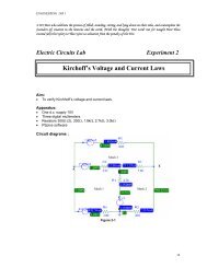
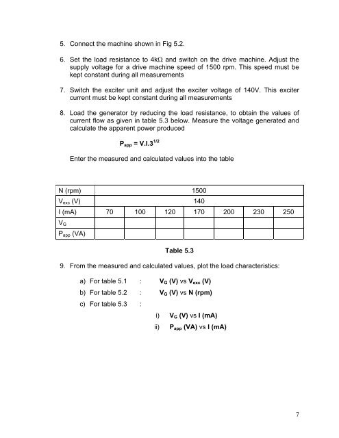
5. Connect the machine shown in Fig 5.2.6. Set the load resistance to 4kΩ and switch on the drive machine. Adjust thesupply voltage for a drive machine speed of 1500 rpm. This speed must bekept constant during all me<strong>as</strong>urements7. Switch the exciter unit and adjust the exciter voltage of 140V. This excitercurrent must be kept constant during all me<strong>as</strong>urements8. Load the generator by reducing the load resistance, to obtain the values ofcurrent flow <strong>as</strong> given in table 5.3 below. Me<strong>as</strong>ure the voltage generated andcalculate the apparent power producedP app = V.I.3 1/2Enter the me<strong>as</strong>ured and calculated values into the tableN (rpm) 1500V exc (V) 140I (mA) 70 100 120 170 200 230 250V GP app (VA)Table 5.39. From the me<strong>as</strong>ured and calculated values, plot the load characteristics:a) For table 5.1 : V G (V) vs V exc (V)b) For table 5.2 : V G (V) vs N (rpm)c) For table 5.3 :i) V G (V) vs I (mA)ii) P app (VA) vs I (mA)7