Tip Vortex Formation and Evolution to the Near Wake of a Rotor in ...
Tip Vortex Formation and Evolution to the Near Wake of a Rotor in ...
Tip Vortex Formation and Evolution to the Near Wake of a Rotor in ...

You also want an ePaper? Increase the reach of your titles
YUMPU automatically turns print PDFs into web optimized ePapers that Google loves.
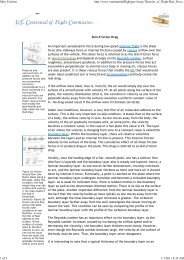
square tip <strong>and</strong> is heavily tip-loaded due <strong>to</strong> <strong>the</strong> constantchord,rectangular planform. The Reynolds number <strong>of</strong><strong>the</strong> tests is high enough <strong>to</strong> <strong>in</strong>volve transition on <strong>the</strong>blades, <strong>and</strong> both <strong>the</strong> freestream turbulence <strong>in</strong>tensity(roughly 0.15%), <strong>the</strong> blade chord, collective pitch <strong>of</strong> 10degrees, <strong>and</strong> <strong>the</strong> surface roughness <strong>of</strong> <strong>the</strong> blade withrough grit over <strong>the</strong> lead<strong>in</strong>g edge up <strong>to</strong> quarter-chord,<strong>and</strong> <strong>the</strong> wooden surface aft <strong>of</strong> that, all contribute <strong>to</strong> <strong>the</strong>development <strong>of</strong> turbulent boundary layers. The seedparticles used are not monodisperse <strong>in</strong> size distribution,<strong>and</strong> some <strong>of</strong> <strong>the</strong>m are expected <strong>to</strong> be <strong>in</strong> <strong>the</strong> regimewhere <strong>the</strong> sp<strong>in</strong>out error must be considered. Except for<strong>the</strong> tip Mach number, <strong>the</strong>se are fairly realistic conditionsfor <strong>in</strong>terpretation <strong>and</strong> application <strong>of</strong> <strong>the</strong> results, as willbe seen.IV. Experimental SetupThese experiments were conducted <strong>in</strong> Georgia Tech’sJohn Harper W<strong>in</strong>d Tunnel. The facility is a closedcircuit tunnel with a 2.13m x 2.74m test section. Airspeed is cont<strong>in</strong>uously variable up <strong>to</strong> 60 m/s. Turbulencelevels are 0.2%. The ro<strong>to</strong>r shaft extends through <strong>the</strong> testsection ceil<strong>in</strong>g <strong>to</strong> <strong>the</strong> centerl<strong>in</strong>e <strong>of</strong> <strong>the</strong> tunnel, <strong>and</strong> istilted forward by 6° <strong>to</strong> simulate forward flight. Attached<strong>to</strong> this shaft is a two-bladed, teeter<strong>in</strong>g, untwisted,untapered, NACA 0015 ro<strong>to</strong>r. The radius <strong>and</strong> bladechord are 9.457m <strong>and</strong> 85.7mm respectively. Testconditions for <strong>the</strong>se experiments were a ro<strong>to</strong>r RPM <strong>of</strong>1050 <strong>and</strong> an advance ratio <strong>of</strong> 0.10. An optical sensor isused <strong>to</strong> generate a TTL 1/rev pulse used for phaseaverag<strong>in</strong>g measurements.Figure 1 - Forward flight experimental setupS<strong>in</strong>gle velocity component measurements were madeus<strong>in</strong>g a laser velocimeter (LV) on <strong>the</strong> advanc<strong>in</strong>g bladeside (ABS). The multi-l<strong>in</strong>e output from a 5W argon-ionlaser is used <strong>to</strong> power <strong>the</strong> laser Doppler velocimeter.The green l<strong>in</strong>e (514.5nm) is separated <strong>and</strong> <strong>the</strong>n split <strong>in</strong><strong>to</strong>two beams, frequency shifted <strong>and</strong> coupled <strong>in</strong> <strong>to</strong> a fiberoptic probe <strong>in</strong> a TSI Colorburst module. The probe ismounted <strong>in</strong> <strong>the</strong> test section <strong>to</strong> a three-axis l<strong>in</strong>eartraverse. The probe <strong>and</strong> traverse are well outside <strong>of</strong> <strong>the</strong>ro<strong>to</strong>r wake <strong>to</strong> m<strong>in</strong>imize <strong>the</strong>ir effects on <strong>the</strong> ro<strong>to</strong>r flowfield. All <strong>of</strong> <strong>the</strong>se measurements were made <strong>in</strong>backscatter mode. The measurement volume is ellipsoidwith a diameter <strong>of</strong> 90.5µm <strong>and</strong> a length <strong>of</strong> 1.31mm. Themeasurement grid consisted <strong>of</strong> a course grid with5.08mm steps <strong>and</strong> a f<strong>in</strong>er grid centered on <strong>the</strong> blade-tipwith 2.54mm steps. The orig<strong>in</strong> for <strong>the</strong>se measurementsis located at <strong>the</strong> blade-tip trail<strong>in</strong>g edge when ψ = 90°.One hundred thous<strong>and</strong> po<strong>in</strong>ts were collected at eachmeasurement location. The data were phase averaged<strong>and</strong> <strong>the</strong>n sorted by ro<strong>to</strong>r azimuth <strong>in</strong><strong>to</strong> b<strong>in</strong>s 0.5° wide.Figure 2 - ABS measurement gridM<strong>in</strong>eral oil is used for <strong>the</strong> LV seed<strong>in</strong>g. The seeder islocated downstream, so particles are drawn through 4turn<strong>in</strong>g vanes, <strong>the</strong> fan, honeycomb <strong>and</strong> screens beforeenter<strong>in</strong>g <strong>the</strong> test section. Particle diameter rangesbetween 1 <strong>and</strong> 5 µm. based on Multiple-Ratio S<strong>in</strong>gle-Particle siz<strong>in</strong>g performed <strong>in</strong> <strong>the</strong> 1980s.S<strong>in</strong>ce previous work [19-20] has shown that <strong>the</strong>flowfield is periodic <strong>to</strong> with<strong>in</strong> 1° <strong>of</strong> ro<strong>to</strong>r azimuth, <strong>the</strong>three-dimensional velocity field can be reconstructedfrom s<strong>in</strong>gle velocity component measurements. Theability <strong>to</strong> reconstruct <strong>the</strong> flow field is vital <strong>to</strong> <strong>the</strong>semeasurements, as <strong>the</strong> ro<strong>to</strong>r <strong>in</strong>terferes withmeasurements for certa<strong>in</strong> azimuths at certa<strong>in</strong> locations.To alleviate <strong>the</strong>se problems, each velocity componentwas measured from two different probe orientations.The two result<strong>in</strong>g datasets had miss<strong>in</strong>g data for differentazimuths. The datasets were <strong>the</strong>n comb<strong>in</strong>ed <strong>to</strong> form onecomplete dataset.Copyright © American Helicopter Society. Presented at <strong>the</strong> 57 th AHS Forum, June 2001

![p density of fluid, kg/m3 [Greek letter rho] V mean velocity of fluid, m ...](https://img.yumpu.com/50595898/1/184x260/p-density-of-fluid-kg-m3-greek-letter-rho-v-mean-velocity-of-fluid-m-.jpg?quality=85)