CALIBRE 1387 R 13 Q CORH CORM 3 jewels (13 x 15.15 x 2.3)
CALIBRE 1387 R 13 Q CORH CORM 3 jewels (13 x 15.15 x 2.3)
CALIBRE 1387 R 13 Q CORH CORM 3 jewels (13 x 15.15 x 2.3)

You also want an ePaper? Increase the reach of your titles
YUMPU automatically turns print PDFs into web optimized ePapers that Google loves.
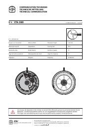
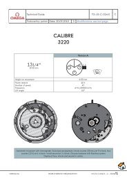
Description<strong>CALIBRE</strong><strong><strong>13</strong>87</strong>R <strong>13</strong> Q <strong>CORH</strong> <strong>CORM</strong> 3 <strong>jewels</strong> (<strong>13</strong> x <strong>15.15</strong> x <strong>2.3</strong>)<strong>13</strong>.00 x <strong>15.15</strong> mmMovement height<strong>2.3</strong>0 mmJewel numberFrequency332'768 A/hGENERAL DESCRIPTIONA new design in quartz watches with itsreduced height, the simple device for timezone changes and the self-blocking gear train.DISPLAY analogue with handsFUNCTIONS hours, minutesCORRECTIONS hours, minutes, secondsynchronization, totally electronic time zonechange by a push-button recessed in the casemiddle at 3 o'clockVARIATION DURING WEAR better than± 5 seconds per month (adjusted to thistolerance if necessary)RESISTANCE TO SHOCKS NIHS shocks: residual effect can be offset by frequencycorrectorRESISTANCE TO MAGNETIC FIELDSbetter than 30 OeTEMPERATURE FUNCTIONINGRANGE from 0˚ to 60˚ CRUNNING TIME average of 2 yearsCONSUMPTION average 0.35 µΑmaximum 0.50 µAYEAR OF CONSTRUCTION 1981DIMENSIONSDiameter <strong>13</strong>.00 x <strong>15.15</strong> mmheight on movement <strong>2.3</strong>0 mmheight on battery <strong>2.3</strong>0 mmEnglishMINIMUM FUNCTIONING VOLTAGE_ 1.35 VBATTERYREFERENCE 9934TYPE silver oxide-zinc (low drain)DIAMETER 6.80 mmHEIGHT 1.60 mmVOLTAGE 1.55 VCAPACITY 15 mAhELECTRONIC MODULETYPE OF RESONATOR quartz tuning-forkFREQUENCY 32768 HzFREQUENCY CORRECTOR trimmerMOTORTYPE electromagnetic with radial field, coilon the same level, step-by-step (2 steps perrevolution, LAVET type)DESIGN integrated, can be disassembledCal. <strong><strong>13</strong>87</strong> 19811
1. DIAGNOSIS Motor impulses 1 per minuteControlsBATTERY VOLTAGE, battery fittedMeasurementsInstruments1.55VALITESTProbes on "input"keyV ExtFREQUENCYbattery fittedfrequencycorrectorMOTOR IMPULSES, battery fitted(see remark)between- 0.25 et+ 0.05 s/dneedle of the instrumentoscillates each minuteDELTATESTkey< 15 hzCAPTORAPU-2ALITESTProbes on "input"keyV ExtMOTOR COIL RESISTANCE,without batteryControl also withoutelectronic modulebetween1.6 - 1.8 KΩALITESTProbes on "input"keyKΩCONSUMPTION, without batterywithout motor impulsemaxi 0.50 µAALITESTProbes on "output"KEYSµA 1.55VMINIMUM FUNCTIONING VOLTAGE,without battery 32 Hz rapid advance(press on corrector)
Remark concerning DIAGNOSISTooling measurement probesThe measurements of the motor impulse and the coilresistance are made with the electronic module coverassembled. The points of the measurement probesshould be sufficiently small in diameter to passthrough the jewel holes of the electronic modulecover.Standard probes with specially sharpened points canbe used. Maxi diameter of probes to pass through thejewel hole : 0.35 mm.Cal. <strong><strong>13</strong>87</strong> 198<strong>13</strong>
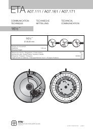
2. DISASSEMBLYOrder of operationsbatteryhands, dial (held by 2 dial screws)electronic module coverelectronic modulebattery clampcoil fittedwheel trainminute wheel trainDO NOT DISASSEMBLE THE STATORRemark Clean the bottom plate with the batteryinsulator.3. CLEANING3.1. Dry cleaning batteryelectronic modulecoil fittedrotor (use cleaning paste for the rotor)3.2. Cleaning by usual bathsall other componentsCal. <strong><strong>13</strong>87</strong> 19814
4. ORDER OF ASSEMBLY AND CONTROLS4.1. Wheel train assembly4.2. Wheel train controlThe wheel train is comprised of a unidirectional gear do not tryto make it turn by moving one of its wheels. Simply checktheir axial clearance.Owing to the magnetic force existing between the magnet andthe stator, the rotor remains suspended between its twobearings.Control the axial clearance of the rotor above and below.4.3. Lubrication1.15 (Synt-A-Lube, 9010 blue)Rotor <strong>jewels</strong>, above and below4.4. Minute wheel train assemblyRemark The short screw 2869 of the minute wheel trainbridge should be screwed close to the corrector.Cal. <strong><strong>13</strong>87</strong> 19815
4.5. Coil and electronic module assemblyGuide with precision the electronic module as it is put in placeat the level of the battery clamp.Hold the electronic module around the screw-feet of the bottomplate for screwing.4.6. Control of the contact clamp<strong><strong>13</strong>87</strong>.9110 corrector <strong><strong>13</strong>87</strong>.9630 contact clampControl the function of the corrector after each intervention.The positioning of the contact clamp must be strictlymaintained.Bend the contact clamp according to illustration withoutdistorting it in the area of the soldered part.Remark To assure good magnetic contact for the motor, theelectronic module cover screws must be well locked.Cal. <strong><strong>13</strong>87</strong> 19816
5. CONTROLS AND ADJUSTMENTS(see 1. Diagnosis)Movement consumption, maxi 0.5 µAMinimum functioning voltage _ 1.20 VAdjustment of the frequency between - 0.25 and + 0.05s/d
6. EXTERIOR COMPONENTS6.1. UncasingTo uncase the watches without an enlarging ring, be carefulnot to use excessive force so as not to pull off the electronicmodule cover. It is advised to make the movement drop out.6.2. Fitting dial and handsDo not forget to put in place the hour wheel friction-spring no.<strong><strong>13</strong>87</strong>.9295 which does not appear in the list of spare parts. Itsthickness is 0.09 mm and on no account should the tension bealtered.Tooling Omega piece-holder no. <strong><strong>13</strong>87</strong>.9000-5112with decentralized supportwith specifically shaped supportwith adjustable supportThe electronic module cover has a countersink allowing thepassage of the support for driving-in the hands.This decentralized fitting supports the buttom plate withouttouching the wheel train bridge.The above-mentioned piece-holder must be used.6.3. Casing upBefore casing, push the springless push button of the casetowards the outside or outside the case.The cases with an enlarging ring generally have a rapidcorrector extension.If the corrector extension has a pivot, it should be turnedtoward the inside.Cal. <strong><strong>13</strong>87</strong> 19818