PLSyn User's Guide
PLSyn User's Guide
PLSyn User's Guide

You also want an ePaper? Increase the reach of your titles
YUMPU automatically turns print PDFs into web optimized ePapers that Google loves.
MicroSim <strong>PLSyn</strong>PLD/CPLD Design SoftwareUser’s <strong>Guide</strong>MicroSim Corporation20 FairbanksIrvine, California 92618(714) 770-3022
Version 8.0, June, 1997.Copyright 1997, MicroSim Corporation. All rights reserved.Printed in the United States of America.TradeMarksReferenced herein are the trademarks used by MicroSim Corporation to identify its products. MicroSimCorporation is the exclusive owners of “MicroSim,” “PSpice,” “PLogic,” “<strong>PLSyn</strong>.”Additional marks of MicroSim include: “StmEd,” “Stimulus Editor,” “Probe,” “Parts,” “Monte Carlo,” “AnalogBehavioral Modeling,” “Device Equations,” “Digital Simulation,” “Digital Files,” “Filter Designer,” “Schematics,”“PLogic,” ”PCBoards,” “PSpice Optimizer,” and “<strong>PLSyn</strong>” and variations theron (collectively the “Trademarks”)are used in connection with computer programs. MicroSim owns various trademark registrations for these marks inthe United States and other countries.SPECCTRA is a registered trademark of Cooper & Chyan Technology, Inc.Microsoft, MS-DOS, Windows, Windows NT and the Windows logo are either registered trademarks or trademarksof Microsoft Corporation.Adobe, the Adobe logo, Acrobat, the Acrobat logo, Exchange and PostScript are trademarks of Adobe SystemsIncorporated or its subsidiaries and may be registered in certain jurisdictions.EENET is a trademark of Eckert Enterprises.All other company/product names are trademarks/registered trademarks of their respective holders.Copyright NoticeExcept as permitted under the United States Copyright Act of 1976, no part of this publication may be reproducedor distributed in any form or by any means, or stored in a data base or retrieval system, without the prior writtenpermission of MicroSim Corporation.As described in the license agreement, you are permitted to run one copy of the MicroSim software on onecomputer at a time. Unauthorized duplication of the software or documentation is prohibited by law. CorporateProgram Licensing and multiple copy discounts are available.Technical SupportInternet Tech.Support@microsim.comPhone (714) 837-0790FAX (714) 455-0554WWWhttp://www.microsim.comCustomer ServiceInternet Sales@MicroSim.comPhone (714) 770-3022
ContentsBefore You BeginWelcome to MicroSim . . . . . . . . . . . . . . . . . . . . . . . . . . . . . . xviiMicroSim <strong>PLSyn</strong> Overview . . . . . . . . . . . . . . . . . . . . . . . . . . . xviiiHow to Use this <strong>Guide</strong> . . . . . . . . . . . . . . . . . . . . . . . . . . . . . . xixTypographical Conventions . . . . . . . . . . . . . . . . . . . . . . . . . . xxRelated Documentation . . . . . . . . . . . . . . . . . . . . . . . . . . . . . xxiOnline Help . . . . . . . . . . . . . . . . . . . . . . . . . . . . . . . . . xxiiThe <strong>PLSyn</strong> Features In Your Configuration . . . . . . . . . . . . . . . . . . . xxiiiChapter 1Chapter 2The Programmable Logic Design Process—An OverviewChapter Overview . . . . . . . . . . . . . . . . . . . . . . . . . . . . . . . . 1-1Steps for Designing Systems with Programmable Logic . . . . . . . . . . . . 1-2Design . . . . . . . . . . . . . . . . . . . . . . . . . . . . . . . . . . . . 1-3Simulate . . . . . . . . . . . . . . . . . . . . . . . . . . . . . . . . . . . 1-3Set Constraints and Priorities . . . . . . . . . . . . . . . . . . . . . . . . 1-4Fit and Partition . . . . . . . . . . . . . . . . . . . . . . . . . . . . . . . 1-4Select Device . . . . . . . . . . . . . . . . . . . . . . . . . . . . . . . . 1-5Simulate with Timing . . . . . . . . . . . . . . . . . . . . . . . . . . . . 1-5Program Device . . . . . . . . . . . . . . . . . . . . . . . . . . . . . . . 1-5Primer: How to Define Programmable LogicChapter Overview . . . . . . . . . . . . . . . . . . . . . . . . . . . . . . . . 2-1Implementing a 3-to-8 Decoder with Programmable Logic . . . . . . . . . . . 2-2Design Phase: Defining Programmable Logic using Schematic Symbols . . . 2-3Before you begin . . . . . . . . . . . . . . . . . . . . . . . . . . . . 2-3Loading and simulating the design . . . . . . . . . . . . . . . . . . . 2-3Converting 74LS Symbols to Programmable Logic . . . . . . . . . . . . 2-4Verifying Functionality using Simulation . . . . . . . . . . . . . . . . . . 2-5
ivContentsImplementation Phase: Fitting and Partitioning the Design . . . . . . . . . . . 2-5Setting Constraints . . . . . . . . . . . . . . . . . . . . . . . . . . . . . . 2-6Setting Priorities . . . . . . . . . . . . . . . . . . . . . . . . . . . . . . . 2-7Partitioning and Fitting . . . . . . . . . . . . . . . . . . . . . . . . . . . 2-7Verifying Timing Behavior using Simulation . . . . . . . . . . . . . . . . 2-8Creating Device Programming Files . . . . . . . . . . . . . . . . . . . . . 2-9Back Annotating the Schematic . . . . . . . . . . . . . . . . . . . . . . . 2-9Using a DSL Block to Define the Programmable Logic . . . . . . . . . . . . 2-10Before You Begin . . . . . . . . . . . . . . . . . . . . . . . . . . . . . 2-10Loading the Design . . . . . . . . . . . . . . . . . . . . . . . . . . . . 2-10Adding a DSL Block . . . . . . . . . . . . . . . . . . . . . . . . . . . . 2-11Defining DSL Source Code . . . . . . . . . . . . . . . . . . . . . . . . 2-11Equivalent Ways to Define the Decoder with DSL . . . . . . . . . . . . 2-13Chapter 3Designing with Programmable LogicChapter Overview . . . . . . . . . . . . . . . . . . . . . . . . . . . . . . . . 3-1The Different Ways to Specify Programmable Logic in Schematics . . . . . . 3-2Using Programmable Logic Symbols . . . . . . . . . . . . . . . . . . . . . . 3-2Generic Logic Symbols . . . . . . . . . . . . . . . . . . . . . . . . . . . 3-274xx Series Logic Symbols . . . . . . . . . . . . . . . . . . . . . . . . . 3-3Using DSL Blocks . . . . . . . . . . . . . . . . . . . . . . . . . . . . . . . . 3-4What Are DSL Blocks? . . . . . . . . . . . . . . . . . . . . . . . . . . . 3-4What Are DSL Procedures? . . . . . . . . . . . . . . . . . . . . . . . . . 3-5Creating a DSL Block in Your Schematic . . . . . . . . . . . . . . . . . . 3-6Using the MicroSim Text Editor to Define DSL Procedures . . . . . . . . 3-7Changing the DSL Block Interface . . . . . . . . . . . . . . . . . . . . . 3-8Using Existing DSL Source Code . . . . . . . . . . . . . . . . . . . . . . 3-9Structuring DSL Source Files . . . . . . . . . . . . . . . . . . . . . . . 3-10Calling DSL Procedures and Functions from within a Procedure . . . . . 3-12Understanding Programmable Logic Nodes . . . . . . . . . . . . . . . . . . 3-13Labeling Nodes . . . . . . . . . . . . . . . . . . . . . . . . . . . . . . 3-13Node naming restrictions . . . . . . . . . . . . . . . . . . . . . . . 3-14Labeling interface nodes . . . . . . . . . . . . . . . . . . . . . . . . 3-14Creating Active-Low Interface Nodes . . . . . . . . . . . . . . . . . . . 3-15Converting Internal Nodes to Interface Nodes . . . . . . . . . . . . . . 3-15Creating Physical Nodes . . . . . . . . . . . . . . . . . . . . . . . . . . 3-15Assigning a Logic 0 or 1 to an Input . . . . . . . . . . . . . . . . . . . . 3-16<strong>Guide</strong>lines for Entering Programmable Logic . . . . . . . . . . . . . . . . . 3-16
ContentsvChapter 4Chapter 5Simulating Programmable Logic DesignsChapter Overview . . . . . . . . . . . . . . . . . . . . . . . . . . . . . . . . 4-1Introduction to Simulating with PLogic or PSpice A/D . . . . . . . . . . . . . 4-2Setting Up Simulations . . . . . . . . . . . . . . . . . . . . . . . . . . . . . 4-3Displaying the Dialog Box for Simulation Setup . . . . . . . . . . . . . . 4-3If you have PLogic . . . . . . . . . . . . . . . . . . . . . . . . . . . 4-3If you have PSpice A/D . . . . . . . . . . . . . . . . . . . . . . . . . 4-3Defining Simulation Setup Options for Programmable Logic . . . . . . . 4-4Starting Simulations . . . . . . . . . . . . . . . . . . . . . . . . . . . . . . . 4-4How the Simulator Uses Programmable Logic I/O Models . . . . . . . . . . . 4-5Simulating with Timing . . . . . . . . . . . . . . . . . . . . . . . . . . . . . 4-6Generating Test Vectors . . . . . . . . . . . . . . . . . . . . . . . . . . . . . 4-6Enabling Test Vector Generation . . . . . . . . . . . . . . . . . . . . . . 4-7If you have PLogic . . . . . . . . . . . . . . . . . . . . . . . . . . . 4-7If you have PSpice A/D . . . . . . . . . . . . . . . . . . . . . . . . . 4-7How the Simulator Responds . . . . . . . . . . . . . . . . . . . . . . . . 4-7Using the “Sample Window” Control . . . . . . . . . . . . . . . . . . . . 4-8Example: How the Simulator Creates Test Vectors . . . . . . . . . . . . . 4-8Troubleshooting Test Vector Differences . . . . . . . . . . . . . . . . . . 4-10Using Probe Markers . . . . . . . . . . . . . . . . . . . . . . . . . . . . . . 4-11A caution about collapsed nodes . . . . . . . . . . . . . . . . . . . . 4-11Creating the Physical ImplementationChapter Overview . . . . . . . . . . . . . . . . . . . . . . . . . . . . . . . . 5-1Overview of the Physical Implementation Process . . . . . . . . . . . . . . . 5-3If You Want More Control . . . . . . . . . . . . . . . . . . . . . . . . . 5-4Where to Find Status and Design Information . . . . . . . . . . . . . . . . . 5-4Activating and Loading <strong>PLSyn</strong> . . . . . . . . . . . . . . . . . . . . . . . . . 5-5Activating <strong>PLSyn</strong> . . . . . . . . . . . . . . . . . . . . . . . . . . . . . . 5-5From Schematics . . . . . . . . . . . . . . . . . . . . . . . . . . . . 5-5From the Windows Program Manager . . . . . . . . . . . . . . . . . 5-5Loading a Different Design . . . . . . . . . . . . . . . . . . . . . . . . . 5-6The <strong>PLSyn</strong> Main Window . . . . . . . . . . . . . . . . . . . . . . . . . 5-6Compiling the Logic . . . . . . . . . . . . . . . . . . . . . . . . . . . . . . . 5-7Manually Compiling Logic . . . . . . . . . . . . . . . . . . . . . . . . . 5-7Compiling DSL Libraries . . . . . . . . . . . . . . . . . . . . . . . . . . 5-8Responding to Compile-Time Status and Errors . . . . . . . . . . . . . . 5-8Controlling Node Generation During Compilation . . . . . . . . . . . . . 5-9Resolving “Out of Memory” Conditions . . . . . . . . . . . . . . . . . . 5-9
viContentsOptimizing the Logic Equations . . . . . . . . . . . . . . . . . . . . . . . . 5-10How the <strong>PLSyn</strong> Optimizer Synthesizes Logic Equations . . . . . . . . . 5-11Choosing the Optimization Method . . . . . . . . . . . . . . . . . . . . 5-13Overview of Fitting and Partitioning Logic . . . . . . . . . . . . . . . . . . 5-14If You Don’t Have the Partitioning Option . . . . . . . . . . . . . . . . 5-14How the <strong>PLSyn</strong> Fitter Works . . . . . . . . . . . . . . . . . . . . . . . 5-15Limiting the PLD Parts Available for Search . . . . . . . . . . . . . . . . . 5-16Constraining Devices . . . . . . . . . . . . . . . . . . . . . . . . . . . . . . 5-18Setting Up User-Defined Constraints . . . . . . . . . . . . . . . . . . . 5-20How <strong>PLSyn</strong> Calculates Maximum Propagation Delay . . . . . . . . . . 5-22The Default Constraints File . . . . . . . . . . . . . . . . . . . . . . . . 5-22Prioritizing the Solutions . . . . . . . . . . . . . . . . . . . . . . . . . . . . 5-23Using Constraints and Priorities Together . . . . . . . . . . . . . . . . . 5-25Running the <strong>PLSyn</strong> Fitter and Partitioner . . . . . . . . . . . . . . . . . . . 5-25Selecting Devices . . . . . . . . . . . . . . . . . . . . . . . . . . . . . . . 5-26Creating Fuse Maps . . . . . . . . . . . . . . . . . . . . . . . . . . . . . . 5-27Including Test Vectors . . . . . . . . . . . . . . . . . . . . . . . . . . . 5-27The Implementation-Specific Physical Information File (.npi) . . . . . . 5-28Updating the Schematic . . . . . . . . . . . . . . . . . . . . . . . . . . . . 5-28Creating PCB Netlists . . . . . . . . . . . . . . . . . . . . . . . . . . . . . 5-29When You Change the Design . . . . . . . . . . . . . . . . . . . . . . . . . 5-30Chapter 6Controlling the Fitting Process Using the .pi FileChapter Overview . . . . . . . . . . . . . . . . . . . . . . . . . . . . . . . . 6-1Introduction to the .pi File . . . . . . . . . . . . . . . . . . . . . . . . . . . . 6-2Why Use the .pi File? . . . . . . . . . . . . . . . . . . . . . . . . . . . . 6-2Using the Default .pi File . . . . . . . . . . . . . . . . . . . . . . . . . . 6-3Referring to Nodes in Your Design . . . . . . . . . . . . . . . . . . . . . 6-3Interface nodes . . . . . . . . . . . . . . . . . . . . . . . . . . . . . . 6-3Internal nodes . . . . . . . . . . . . . . . . . . . . . . . . . . . . . . 6-3Controlling PLD Utilization . . . . . . . . . . . . . . . . . . . . . . . . . . . 6-5Fitting a Node as an OUTPUT or NODE . . . . . . . . . . . . . . . . . . . . 6-6Controlling How Signals Are Fit Together . . . . . . . . . . . . . . . . . . . 6-6Disabling Outputs for Test . . . . . . . . . . . . . . . . . . . . . . . . . . . . 6-8Controlling Synthesis . . . . . . . . . . . . . . . . . . . . . . . . . . . . . . 6-9Cautions when using the DEMORGAN_SYNTH property . . . . . . . 6-9Controlling the Size of Equations . . . . . . . . . . . . . . . . . . . . . . . 6-10Specifying Devices without Specifying Signals . . . . . . . . . . . . . . . . 6-11Specifying JEDEC File Names . . . . . . . . . . . . . . . . . . . . . . . . . 6-12
ContentsviiMore Examples Using the .pi File . . . . . . . . . . . . . . . . . . . . . . . . 6-13Forcing Signals to be Fit Together in the Same Device . . . . . . . . . . . 6-13Using Specific Devices . . . . . . . . . . . . . . . . . . . . . . . . . . . 6-14Maintaining Pin Assignments . . . . . . . . . . . . . . . . . . . . . . . . 6-15Fitting the Design into One Device . . . . . . . . . . . . . . . . . . . . . 6-16Fitting the Design into Multiple Devices . . . . . . . . . . . . . . . . . . 6-17Mixing Automatic and Directed Partitioning . . . . . . . . . . . . . . . . 6-17Refitting a Design into the Same Footprint . . . . . . . . . . . . . . . . . 6-18Chapter 7Chapter 8PLD Device-Specific FittingChapter Overview . . . . . . . . . . . . . . . . . . . . . . . . . . . . . . . . 7-1Accessing Internal Points in a PLD Device . . . . . . . . . . . . . . . . . . . 7-2The Kinds of Nodes . . . . . . . . . . . . . . . . . . . . . . . . . . . . . 7-2Hidden nodes . . . . . . . . . . . . . . . . . . . . . . . . . . . . . . 7-2Unary nodes . . . . . . . . . . . . . . . . . . . . . . . . . . . . . . . 7-4Unary Nodes in the P330 and P331 . . . . . . . . . . . . . . . . . . . . . 7-8Fitting Specific Device Architectures . . . . . . . . . . . . . . . . . . . . . . 7-1122V10, 750, and 2500: Handling Synchronous Preset . . . . . . . . . . . 7-11Using set and preset for the 22V10 and 750 . . . . . . . . . . . . . . 7-11Using set and preset for the 2500 . . . . . . . . . . . . . . . . . . . . 7-12P22V10I: Assigning Combinatorial Output During Feedback . . . . . . . 7-13P750B AND P2500B: Controlling Clock Source . . . . . . . . . . . . . . 7-14P1800: Controlling Quadrant-Based Architectures . . . . . . . . . . . . . 7-16Assigning pins and nodes . . . . . . . . . . . . . . . . . . . . . . . . 7-16Subgroups: Targeting quadrants . . . . . . . . . . . . . . . . . . . . 7-17P16V8HD, P22VP10, and P16VP10: Accessing theOpen-Drain Output . . . . . . . . . . . . . . . . . . . . . . . . . 7-17MACH 1-4 Device-Specific FittingChapter Overview . . . . . . . . . . . . . . . . . . . . . . . . . . . . . . . . 8-1Designing with MACH Devices . . . . . . . . . . . . . . . . . . . . . . . . . 8-2When You Have Fitting Problems . . . . . . . . . . . . . . . . . . . . . 8-2Using the log file . . . . . . . . . . . . . . . . . . . . . . . . . . . . 8-2Using the report file . . . . . . . . . . . . . . . . . . . . . . . . . . . 8-2Summary of MACH Devices . . . . . . . . . . . . . . . . . . . . . . . . . . 8-3Output Enable Functions . . . . . . . . . . . . . . . . . . . . . . . . . . 8-3Register Reset/Preset Functions . . . . . . . . . . . . . . . . . . . . . . . 8-4Packaging . . . . . . . . . . . . . . . . . . . . . . . . . . . . . . . . . . 8-4
viiiContentsUsing Standard Clock Functions . . . . . . . . . . . . . . . . . . . . . . . . . 8-5MACH 1xx, MACH 2xx: Synchronous Clock Functions . . . . . . . . 8-5MACH 215, 3xx, 4xx: Asynchronous Clock Functions . . . . . . . . . 8-5Using Complex Clock Functions . . . . . . . . . . . . . . . . . . . . . . . . . 8-6Clock Limitations . . . . . . . . . . . . . . . . . . . . . . . . . . . . . . 8-7Implementing Hazard-Free Combinatorial Latches . . . . . . . . . . . . . . . 8-8Basic Latch Circuit . . . . . . . . . . . . . . . . . . . . . . . . . . . . . . 8-8Creating a Hazard-Free Latch . . . . . . . . . . . . . . . . . . . . . . . . 8-8Specifying Reserve Capacity . . . . . . . . . . . . . . . . . . . . . . . . . . . 8-9Targeting PAL Blocks . . . . . . . . . . . . . . . . . . . . . . . . . . . . . 8-10Using Signal Groups . . . . . . . . . . . . . . . . . . . . . . . . . . . . 8-10Using Device Sections . . . . . . . . . . . . . . . . . . . . . . . . . . . 8-11Constraining the Size of Combinatorial Nodes . . . . . . . . . . . . . . . . 8-13Making Adjustments . . . . . . . . . . . . . . . . . . . . . . . . . . . . 8-13Optimizing MACH 4xx Devices Using MAX_XOR_PTERMS . . . . . 8-15A Few Considerations . . . . . . . . . . . . . . . . . . . . . . . . . . . 8-15Other Optimizing Parameters . . . . . . . . . . . . . . . . . . . . . . . 8-16Understanding Pin Naming and Numbering . . . . . . . . . . . . . . . . . . 8-17Using the MACROCELL_X## notation . . . . . . . . . . . . . . . 8-18Using the IN_REG_X## notation . . . . . . . . . . . . . . . . . . . 8-18Achieving Satisfactory Pinouts . . . . . . . . . . . . . . . . . . . . . . . . 8-19MACH 2xx, 4xx: Using Input Registers . . . . . . . . . . . . . . . . . . . . 8-23Understanding Input Register Pin Names . . . . . . . . . . . . . . . . . 8-23MACH 2xx and 4xx Compared . . . . . . . . . . . . . . . . . . . . . . 8-24Input Registration . . . . . . . . . . . . . . . . . . . . . . . . . . . . . 8-24Finding Signals Fit as Unary . . . . . . . . . . . . . . . . . . . . . . . . 8-25Forcing a Function to be Fit as Unary . . . . . . . . . . . . . . . . . . . 8-26Preventing a Function from Being Fit as Unary . . . . . . . . . . . . . . 8-26Preserving Pinouts when Refitting . . . . . . . . . . . . . . . . . . . . . . . 8-27Plan for Refitting . . . . . . . . . . . . . . . . . . . . . . . . . . . . . . 8-27Method 1: Creating a Two-Level .pi File . . . . . . . . . . . . . . . . . 8-28Method 2: Floating Nodes . . . . . . . . . . . . . . . . . . . . . . . . . 8-34When Fitting into One Device Fails . . . . . . . . . . . . . . . . . . . . . . 8-35Using the “Default” Signal Reference . . . . . . . . . . . . . . . . . . . 8-35What you can find out in the log file . . . . . . . . . . . . . . . . . 8-36What you can find out in the report file . . . . . . . . . . . . . . . . 8-36Using a Second Device . . . . . . . . . . . . . . . . . . . . . . . . . . 8-37Accessing the MACH Internal Feedback Path . . . . . . . . . . . . . . . . . 8-38MACH 215, 4xx: Fitting Asynchronous Functions . . . . . . . . . . . . . . 8-40PTERM Clock and RESET and PRESET . . . . . . . . . . . . . . . . . 8-40More Than One RESET/PRESET Pair per PAL Block . . . . . . . . . . 8-40MACH 4xx: Using XOR T-Equations . . . . . . . . . . . . . . . . . . . . . 8-41
ContentsixMACH 4xx: Controlling Asynchronous Mode . . . . . . . . . . . . . . . . . 8-42MACH 4xx: Controlling T-Flop Synthesis . . . . . . . . . . . . . . . . . . . 8-43Normal Operation . . . . . . . . . . . . . . . . . . . . . . . . . . . . . . 8-43DFF-Only Fitting . . . . . . . . . . . . . . . . . . . . . . . . . . . . . . 8-43Using the T-Equation . . . . . . . . . . . . . . . . . . . . . . . . . . . . 8-44MACH 4xx: Controlling Power-On Reset . . . . . . . . . . . . . . . . . . . 8-44What Is a Logical Reset? . . . . . . . . . . . . . . . . . . . . . . . . . . 8-44The Nominal Case . . . . . . . . . . . . . . . . . . . . . . . . . . . . . . 8-45Exception Cases . . . . . . . . . . . . . . . . . . . . . . . . . . . . . . . 8-45MACH 230 and 435: Possible Pin Incompatibility Between . . . . . . . . . . 8-46MACH 445 and 465: Configuring for Zero-Hold Time . . . . . . . . . . . . . 8-47MACH 445 and 465: Accessing Signature Bits . . . . . . . . . . . . . . . . . 8-48MACH 1xx and 2xx: Driving or Floating Unused Outputs . . . . . . . . . . . 8-49Forcing Outputs Driven . . . . . . . . . . . . . . . . . . . . . . . . . . . 8-49Forcing Outputs Floating . . . . . . . . . . . . . . . . . . . . . . . . . . 8-50The MACH Report File . . . . . . . . . . . . . . . . . . . . . . . . . . . . . 8-52Obtaining a Report File . . . . . . . . . . . . . . . . . . . . . . . . . . . 8-52Contents of the Report File . . . . . . . . . . . . . . . . . . . . . . . . . 8-53Failure Disclaimers . . . . . . . . . . . . . . . . . . . . . . . . . . . . . 8-54Summary Statistics . . . . . . . . . . . . . . . . . . . . . . . . . . . . . 8-56Device Resource Utilization . . . . . . . . . . . . . . . . . . . . . . . . 8-58Partitioner Report . . . . . . . . . . . . . . . . . . . . . . . . . . . . . . 8-60Clock Assignments . . . . . . . . . . . . . . . . . . . . . . . . . . . . . 8-60Signal Directory . . . . . . . . . . . . . . . . . . . . . . . . . . . . . . . 8-61Resource Assignment Map . . . . . . . . . . . . . . . . . . . . . . . . . 8-63PTERM steering of clusters . . . . . . . . . . . . . . . . . . . . . . . 8-66Chapter 9MACH 5 Device-Specific FittingChapter Overview . . . . . . . . . . . . . . . . . . . . . . . . . . . . . . . . 9-1Comparing the MACH 5 to Other MACH Architectures . . . . . . . . . . . . 9-2MACH1xx/2xx/3xx/4xx . . . . . . . . . . . . . . . . . . . . . . . . . . 9-3MACH5xx . . . . . . . . . . . . . . . . . . . . . . . . . . . . . . . . . . 9-4Using the .pi File to Control MACH 5 Fitting . . . . . . . . . . . . . . . . . . 9-5Routing in a Segment and Block . . . . . . . . . . . . . . . . . . . . . . . . 9-6Assigning Pins and Nodes . . . . . . . . . . . . . . . . . . . . . . . . . . . . 9-7Placing a Signal on an Input Register or Latch . . . . . . . . . . . . . . . . . 9-9Using Dual Feedback . . . . . . . . . . . . . . . . . . . . . . . . . . . . . . 9-10Forcing the Feedback Path to be Local . . . . . . . . . . . . . . . . . . . . . 9-11Specifying Fanout . . . . . . . . . . . . . . . . . . . . . . . . . . . . . . . . 9-12Implementing Toggle Register Feedback . . . . . . . . . . . . . . . . . . . . 9-14Implementing Dual-Edge Clocking . . . . . . . . . . . . . . . . . . . . . . . 9-15
xContentsChapter 10Specifying Reserve Capacity . . . . . . . . . . . . . . . . . . . . . . . . . . 9-16Constraining the Size of Combinatorial Nodes . . . . . . . . . . . . . . . . 9-17Making Adjustments . . . . . . . . . . . . . . . . . . . . . . . . . . . . 9-17A Few Considerations . . . . . . . . . . . . . . . . . . . . . . . . . . . 9-18Other Optimizing Parameters . . . . . . . . . . . . . . . . . . . . . . . 9-19Controlling Power Levels . . . . . . . . . . . . . . . . . . . . . . . . . . . 9-19Controlling Slew Rates . . . . . . . . . . . . . . . . . . . . . . . . . . . . . 9-20The Document File . . . . . . . . . . . . . . . . . . . . . . . . . . . . . . . 9-21The Report File . . . . . . . . . . . . . . . . . . . . . . . . . . . . . . . . . 9-22Heading . . . . . . . . . . . . . . . . . . . . . . . . . . . . . . . . . . 9-22Summary Statistics . . . . . . . . . . . . . . . . . . . . . . . . . . . . . 9-23Power Resource Utilization . . . . . . . . . . . . . . . . . . . . . . . . 9-24Device Resource Utilization . . . . . . . . . . . . . . . . . . . . . . . . 9-24Partition Groups . . . . . . . . . . . . . . . . . . . . . . . . . . . . . . 9-27Signal Directory . . . . . . . . . . . . . . . . . . . . . . . . . . . . . . 9-28Fanout Table . . . . . . . . . . . . . . . . . . . . . . . . . . . . . . . . 9-30Power Table . . . . . . . . . . . . . . . . . . . . . . . . . . . . . . . . 9-32Block Configuration Tables . . . . . . . . . . . . . . . . . . . . . . . . 9-32ATV5000 Device-Specific FittingChapter Overview . . . . . . . . . . . . . . . . . . . . . . . . . . . . . . . 10-1Designing with the ATV5000 . . . . . . . . . . . . . . . . . . . . . . . . . 10-2Constraining the Size of Combinatorial Nodes . . . . . . . . . . . . . . . . 10-2The Effect of MAX_PTERMS . . . . . . . . . . . . . . . . . . . . . . 10-3The Effect of MAX_SYMBOLS . . . . . . . . . . . . . . . . . . . . . 10-4Specifying Device Utilization . . . . . . . . . . . . . . . . . . . . . . . . . 10-5Using the Flip-Flop Clock Option . . . . . . . . . . . . . . . . . . . . . . . 10-5Enabling Clocking . . . . . . . . . . . . . . . . . . . . . . . . . . . . . 10-6Controlling the Clock Source . . . . . . . . . . . . . . . . . . . . . . . 10-6Using the I/O Pin Latches . . . . . . . . . . . . . . . . . . . . . . . . . . . 10-8Identifying Pins and Nodes . . . . . . . . . . . . . . . . . . . . . . . . . . . 10-8Targeting Quadrants in the ATV5000 . . . . . . . . . . . . . . . . . . . . . 10-10Using the GROUP Construct . . . . . . . . . . . . . . . . . . . . . . . 10-10Using the SECTION Construct . . . . . . . . . . . . . . . . . . . . . . 10-11Placing Node Signals on Buried Logic Cells . . . . . . . . . . . . . . . . . 10-13Understanding RU Conversion . . . . . . . . . . . . . . . . . . . . . . . . . 10-14
ContentsxiUnderstanding Regionalization . . . . . . . . . . . . . . . . . . . . . . . . 10-14Universal and regional PTERMs . . . . . . . . . . . . . . . . . . . 10-14Regionalization, sum-term combining, and fitting PTERMs . . . . . 10-15How <strong>PLSyn</strong> Does Regionalization . . . . . . . . . . . . . . . . . . . . 10-16Signal Regionalization . . . . . . . . . . . . . . . . . . . . . . . . . . 10-16Using input pins . . . . . . . . . . . . . . . . . . . . . . . . . . . . 10-16Using feedback paths (UR conversion) . . . . . . . . . . . . . . . . 10-17PTERM Regionalization . . . . . . . . . . . . . . . . . . . . . . . . . 10-17The Report File . . . . . . . . . . . . . . . . . . . . . . . . . . . . . . . . 10-18Obtaining Report File . . . . . . . . . . . . . . . . . . . . . . . . . . . 10-18Heading . . . . . . . . . . . . . . . . . . . . . . . . . . . . . . . . . . 10-19Failure-to-Partition Disclaimer . . . . . . . . . . . . . . . . . . . . . . 10-20Partitioner Report . . . . . . . . . . . . . . . . . . . . . . . . . . . . . 10-20Signal Directory . . . . . . . . . . . . . . . . . . . . . . . . . . . . . . 10-20Signals Universalized on Sum Term B . . . . . . . . . . . . . . . . . . 10-22Signals Regionalized on Input Pins . . . . . . . . . . . . . . . . . . . . 10-22Function Placement Report . . . . . . . . . . . . . . . . . . . . . . . . 10-22Quadrant sections . . . . . . . . . . . . . . . . . . . . . . . . . . . 10-22Fit attempt sections . . . . . . . . . . . . . . . . . . . . . . . . . . 10-23UR conversion report . . . . . . . . . . . . . . . . . . . . . . . . . 10-23Pterm regionalization report . . . . . . . . . . . . . . . . . . . . . 10-23Output/node signal placement report . . . . . . . . . . . . . . . . . 10-23Input Signal Placement Report . . . . . . . . . . . . . . . . . . . . . . 10-24Failure-to-Fit Disclaimer . . . . . . . . . . . . . . . . . . . . . . . . . 10-24Appendix AThe Documentation FileAppendix Overview . . . . . . . . . . . . . . . . . . . . . . . . . . . . . . . A-1Summary of Documentation File Contents . . . . . . . . . . . . . . . . . . . A-2Reduced Design Equations . . . . . . . . . . . . . . . . . . . . . . . . . . . A-3Equation Extensions Used in the .doc File . . . . . . . . . . . . . . . . . A-3DeMorgan Equations . . . . . . . . . . . . . . . . . . . . . . . . . . . . A-4Equation Display . . . . . . . . . . . . . . . . . . . . . . . . . . . . . . A-5Partitioning Criteria . . . . . . . . . . . . . . . . . . . . . . . . . . . . . . . A-6Solutions List . . . . . . . . . . . . . . . . . . . . . . . . . . . . . . . . . . A-6Fuse Map Files . . . . . . . . . . . . . . . . . . . . . . . . . . . . . . . . . . A-6Pinout Diagrams . . . . . . . . . . . . . . . . . . . . . . . . . . . . . . . . . A-7Possible Devices List . . . . . . . . . . . . . . . . . . . . . . . . . . . . . . A-7Wire List . . . . . . . . . . . . . . . . . . . . . . . . . . . . . . . . . . . . . A-7
xiiContentsAppendix BSummary of FilesAppendix Overview . . . . . . . . . . . . . . . . . . . . . . . . . . . . . . . B-1Files Used by <strong>PLSyn</strong> . . . . . . . . . . . . . . . . . . . . . . . . . . . . . . . B-2Appendix CAMD MACH Device TablesAppendix Overview . . . . . . . . . . . . . . . . . . . . . . . . . . . . . . . C-1Pin Name Tables . . . . . . . . . . . . . . . . . . . . . . . . . . . . . . . . . C-2MACH 110 . . . . . . . . . . . . . . . . . . . . . . . . . . . . . . . C-2MACH 111, 111SP . . . . . . . . . . . . . . . . . . . . . . . . . . . C-2MACH 120, 121 . . . . . . . . . . . . . . . . . . . . . . . . . . . . . C-3MACH 130, 131, 131SP . . . . . . . . . . . . . . . . . . . . . . . . . C-3MACH 210, 211, 211SP . . . . . . . . . . . . . . . . . . . . . . . . . C-4MACH 215 . . . . . . . . . . . . . . . . . . . . . . . . . . . . . . . C-5MACH 220, 221, 221SP . . . . . . . . . . . . . . . . . . . . . . . . . C-6MACH 230, 231 . . . . . . . . . . . . . . . . . . . . . . . . . . . . . C-7MACH 435, 436 . . . . . . . . . . . . . . . . . . . . . . . . . . . . . C-8MACH 445, 446 . . . . . . . . . . . . . . . . . . . . . . . . . . . . . C-9MACH 465, 466 . . . . . . . . . . . . . . . . . . . . . . . . . . . . C-10MACH 1xx and 2xx: Fuse Commands for Driving Outputs . . . . . . . . . . C-12MACH 110 . . . . . . . . . . . . . . . . . . . . . . . . . . . . . . C-12MACH 120 . . . . . . . . . . . . . . . . . . . . . . . . . . . . . . C-13MACH 130 . . . . . . . . . . . . . . . . . . . . . . . . . . . . . . C-14MACH 210 . . . . . . . . . . . . . . . . . . . . . . . . . . . . . . C-16MACH 215 . . . . . . . . . . . . . . . . . . . . . . . . . . . . . . C-17MACH 220 . . . . . . . . . . . . . . . . . . . . . . . . . . . . . . C-18MACH 230 . . . . . . . . . . . . . . . . . . . . . . . . . . . . . . C-20
FiguresFigure 1-1 PLD Synthesis Design Flow . . . . . . . . . . . . . . . . . . . . . . . . . . . 1-2Figure 2-1 3-to-8 Decoder Schematic . . . . . . . . . . . . . . . . . . . . . . . . . . . . 2-2Figure 2-2 Results of Decoder Simulation . . . . . . . . . . . . . . . . . . . . . . . . . 2-4Figure 2-3 Back-Annotated Schematic Page . . . . . . . . . . . . . . . . . . . . . . . . 2-9Figure 2-4 The decoder1.sch Example Schematic . . . . . . . . . . . . . . . . . . . . . 2-10Figure 2-5 Connecting the DSL Block . . . . . . . . . . . . . . . . . . . . . . . . . . . 2-11Figure 2-6 Finished DSL Block . . . . . . . . . . . . . . . . . . . . . . . . . . . . . . . 2-11Figure 3-1 7400 Symbol as Programmable Logic . . . . . . . . . . . . . . . . . . . . . . 3-3Figure 3-2 Relation of PLMODEL Attribute and DSL Procedure Name . . . . . . . . . . 3-5Figure 3-3 The DSL Procedure Template . . . . . . . . . . . . . . . . . . . . . . . . . . 3-8Figure 3-4 A Source Code File for Each DSL Block . . . . . . . . . . . . . . . . . . . . 3-10Figure 3-5 Single DSL Source Code File with More Than One Procedure . . . . . . . . . 3-11Figure 3-6 Programmable Logic Interface Node Labeled with a Global Port . . . . . . . 3-14Figure 5-1 Main <strong>PLSyn</strong> Window . . . . . . . . . . . . . . . . . . . . . . . . . . . . . . 5-6Figure 5-2 <strong>PLSyn</strong> Functional Architecture . . . . . . . . . . . . . . . . . . . . . . . . . 5-15Figure 7-1 Hidden Node . . . . . . . . . . . . . . . . . . . . . . . . . . . . . . . . . . . 7-2Figure 7-2 Shadow Node . . . . . . . . . . . . . . . . . . . . . . . . . . . . . . . . . . 7-3Figure 7-3 Input Unary . . . . . . . . . . . . . . . . . . . . . . . . . . . . . . . . . . . 7-4Figure 7-4 Feedback Unary . . . . . . . . . . . . . . . . . . . . . . . . . . . . . . . . . 7-4Figure 7-5 P33x Local Unary . . . . . . . . . . . . . . . . . . . . . . . . . . . . . . . . 7-9Figure 7-6 P33x Shared Unary . . . . . . . . . . . . . . . . . . . . . . . . . . . . . . . 7-9Figure 9-1 Simplified MACH 1xx/2xx/3xx/4xx Block Diagrams . . . . . . . . . . . . . 9-3Figure 9-2 Simplified 5xx Block Diagram . . . . . . . . . . . . . . . . . . . . . . . . . 9-5Figure 9-3 Mach 5 Architecture . . . . . . . . . . . . . . . . . . . . . . . . . . . . . . . 9-7
TablesTable 4-1 <strong>PLSyn</strong> I/O Models . . . . . . . . . . . . . . . . . . . . . . . . . . . . . . . . 4-5Table 4-2 Test Vectors for Case 1 . . . . . . . . . . . . . . . . . . . . . . . . . . . . . 4-8Table 4-3 Test Vectors for Case 2 . . . . . . . . . . . . . . . . . . . . . . . . . . . . . 4-9Table 4-4 Test Vectors for Corrected Case 2 . . . . . . . . . . . . . . . . . . . . . . . . 4-10Table 5-2 Temperature Rating Abbreviations . . . . . . . . . . . . . . . . . . . . . . . 5-19Table 5-1 Device Selection Constraints Dialog Box Controls . . . . . . . . . . . . . . . 5-19Table 5-3 Solution Priorities Dialog Box Controls . . . . . . . . . . . . . . . . . . . . . 5-23Table 6-1 PLD Utilization Properties . . . . . . . . . . . . . . . . . . . . . . . . . . . 6-5Table 6-2 Synthesis Control Properties . . . . . . . . . . . . . . . . . . . . . . . . . . . 6-10Table 7-1 Node Descriptions and Labels by Device Architecture . . . . . . . . . . . . . 7-6Table 7-2 Node Descriptions and Labels for P330 and P331 . . . . . . . . . . . . . . . 7-10Table 7-3 Node Descriptions and Labels for P1800 . . . . . . . . . . . . . . . . . . . . 7-16Table 8-1 MACH Device Properties . . . . . . . . . . . . . . . . . . . . . . . . . . . . 8-3Table 8-2 MACH PAL Block Names . . . . . . . . . . . . . . . . . . . . . . . . . . . 8-11Table 8-3 Minimum and Maximum Number of PTERMS . . . . . . . . . . . . . . . . . 8-14Table 9-1 MACH 5 Node Names and Pin Numbers . . . . . . . . . . . . . . . . . . . . 9-8Table 10-1 Equation Extensions Used in the .doc File . . . . . . . . . . . . . . . . . . . A-3Table 10-2 MACH 110 OE Fuse Commands . . . . . . . . . . . . . . . . . . . . . . . C-12Table 10-3 MACH 120 OE Fuse Commands . . . . . . . . . . . . . . . . . . . . . . . C-13Table 10-4 MACH 130 OE Fuse Commands . . . . . . . . . . . . . . . . . . . . . . . C-14Table 10-5 MACH 210 OE Fuse Commands . . . . . . . . . . . . . . . . . . . . . . . C-16Table 10-6 MACH 215 OE Fuse Commands . . . . . . . . . . . . . . . . . . . . . . . C-17Table 10-7 MACH 220 OE Fuse Commands . . . . . . . . . . . . . . . . . . . . . . . C-18Table 10-8 MACH 230 OE Fuse Commands . . . . . . . . . . . . . . . . . . . . . . . C-20
Before You BeginWelcome to MicroSimWelcome to the MicroSim family of products. Whicheverprograms you have purchased, we are confident that you willfind that they meet your circuit design needs. They provide aneasy-to-use, integrated environment for creating, simulating,and analyzing your circuit designs from start to finish.
xviiiBefore You BeginMicroSim <strong>PLSyn</strong>OverviewMicroSim <strong>PLSyn</strong> is a programmable logic synthesis programthat allows you to synthesize all or any portion of your designinto PLD and/or CPLD parts.<strong>PLSyn</strong> is fully integrated with other MicroSim programs. Thismeans you can do all of the following within the sameenvironment:• Design your circuit with MicroSim Schematics.• Synthesize programmable logic with MicroSim <strong>PLSyn</strong>.• Simulate with MicroSim PSpice A/D (for mixed digital andanalog simulation) or MicroSim PLogic (for digital logicand timing simulation).• Analyze simulation results with MicroSim Probe.MicroSimSchematicsMicroSimPCBoardssymbolspackagesMicroSimPSpiceOptimizerMicroSimPartsMODEL+BF =MicroSimPSpice A/DMicroSim<strong>PLSyn</strong>SPECCTRA®AutorouterpackagesfootprintspadstacksmodelsMicroSimProbePLDdevicesGerberfilesdrillfilesreports
How to Use this <strong>Guide</strong>This guide is designed so you can quickly find the informationyou need to use <strong>PLSyn</strong>, including:• how to create and edit designs which use PLDs (schematicand language-based), and• how to optimize, partition, and fit devices.This guide assumes that you are familiar with MicrosoftWindows (NT or 95), including how to use icons, menus, anddialog boxes. It also assumes you have a basic understandingabout how Windows manages applications and files to performroutine tasks, such as starting applications and opening, andsaving your work. If you are new to Windows, please reviewyour Microsoft Windows User’s <strong>Guide</strong>.How to Use this <strong>Guide</strong>xix
xxBefore You BeginTypographical ConventionsBefore using <strong>PLSyn</strong>, you need to understand the terms andtypographical conventions used in this documentation.This guide generally follows the conventions used in theMicrosoft Windows User’s <strong>Guide</strong>. Procedures for performing anoperation are generally numbered with the followingtypographical conventions.Notation Examples DescriptionC + r Press C+r A specific key or key strokeon the keyboard.monospacefontType VAC... ordig_prim.slbPartitioningOptionRequiredTo improveaccuracy...Be careful...Commands/text entered fromthe keyboard, or file names.Feature available in systemswith the partitioning optiononlyTip providing advice ordifferent ways to do things.Cautionary message.
Related DocumentationDocumentation for MicroSim products is available in both hardcopy and online. To access an online manual instantly, you canselect it from the Help menu in its respective program (forexample, access the Schematics User’s <strong>Guide</strong> from the Helpmenu in Schematics).Note The documentation you receive depends on thesoftware configuration you have purchased.The following table provides a brief description of thosemanuals available in both hard copy and online.Related DocumentationxxiThis manual...MicroSim SchematicsUser’s <strong>Guide</strong>MicroSim PCBoardsUser’s <strong>Guide</strong>MicroSim PSpice A/D & Basics+User’s <strong>Guide</strong>MicroSim PSpice & BasicsUser’s <strong>Guide</strong>MicroSim PSpice OptimizerUser’s <strong>Guide</strong>MicroSim FPGAUser’s <strong>Guide</strong>MicroSim Filter DesignerUser’s <strong>Guide</strong>Provides information about how to use...MicroSim Schematics, which is a schematic capture front-end programwith a direct interface to other MicroSim programs and options.MicroSim PCBoards, which is a PCB layout editor that lets you specifyprinted circuit board structure, as well as the components, metal, andgraphics required for fabrication.PSpice A/D, Probe, the Stimulus Editor, and the Parts utility, which arecircuit analysis programs that let you create, simulate, and test analog anddigital circuit designs. It provides examples on how to specify simulationparameters, analyze simulation results, edit input signals, and createmodels.MicroSim PSpice & MicroSim PSpice Basics, which are circuit analysisprograms that let you create, simulate, and testanalog-only circuit designs.MicroSim PSpice Optimizer, which is an analog performanceoptimization program that lets you fine tune your analog circuit designs.MicroSim FPGA—the interface between MicroSim Schematics andXACTstep—with MicroSim PSpice A/D to enter designs that includeXilinx field programmable gate array devices.MicroSim Filter Designer, which is a filter synthesis program that lets youdesign electronic frequency selective filters.
xxiiBefore You BeginThe following table provides a brief description of thosemanuals available online only.This online manual...MicroSim PSpice A/DOnline Reference ManualMicroSim Application NotesOnline ManualOnline Library ListMicroSim PCBoards OnlineReference ManualMicroSim PCBoards AutorouterOnline User’s <strong>Guide</strong>Provides this...Reference material for PSpice A/D. Also included: detailed descriptions of thesimulation controls and analysis specifications, start-up option definitions, anda list of device types in the analog and digital model libraries. User interfacecommands are provided to instruct you on each of the screen commands.A variety of articles that show you how a particular task can be accomplishedusing MicroSim‘s products, and examples that demonstrate a new or differentapproach to solving an engineering problem.A complete list of the analog and digital parts in the model and symbollibraries.Reference information for MicroSim PCBoards, such as: file name extensions,padstack naming conventions and standards, footprint naming conventions, thenetlist file format, the layout file format, and library expansion andcompression utilities.Information on the integrated interface to Cooper & Chyan Technology’s(CCT) SPECCTRA autorouter in MicroSim PCBoards.Online HelpSelecting Search for Help On from the Help menu brings up anextensive online help system.The online help includes:• step-by-step instructions on how to use <strong>PLSyn</strong> features• DSL language reference• PIL language reference• device lists (by manufacturer and by template)• Technical Support informationEvery dialog box also includes a help button which, whenselected, displays a description of the dialog box and eachcontrol.
The <strong>PLSyn</strong> Features InYour ConfigurationThe <strong>PLSyn</strong> Features In Your Configurationxxiii<strong>PLSyn</strong>, running with other MicroSim programs, provides thefollowing features:• Multiple design entry modes.• Schematic entry with support for hierarchical design.• Design Synthesis Language (DSL) support of arithmeticoperators and arrays, procedure and function library linking.• Device-independent design entry.• Integrated simulation at the system level to detect problemareas in the design; you can simulate the functionality ofyour design while it is still in the design phase.• Compilation, optimization, and device selection.• Logic consolidation; optimization and reduction of yourdesign to the smallest set of gates using industry-standardmethods.• Multiple equation reduction levels; automaticDeMorganization, automatic flip-flop synthesis, XORsynthesis, don’t care generation, and node collapsing.• Automatic or manual placement of input and output signalsin the selected programmable logic devices.• Automatic partitioning of the design across as many as 20devices.• Libraries with up to 3,500 PLDs from twelve manufacturersand 100+ architectures.• Ability to test programmable devices by automaticallygenerating test vectors from the functional simulationresults and downloading them to the programmer with thefuse map file.• On-line reference to the complete list of devices supportedby <strong>PLSyn</strong>.PartitioningOptionRequiredYour configuration depends onwhich of the design modules youpurchased: PLDs, AMD MACH,and/or Atmel V-Series.
The Programmable LogicDesign Process—AnOverview1Chapter OverviewThis chapter introduces the programmable logic design process,and terms and concepts used throughout this manual. Topicsinclude:• Design entry, page 1-3• Functional simulation, page 1-3• Constraints and priorities definition, page 1-4• Fitting and partitioning process, page 1-4• Device selection, page 1-5• Timing simulation, page 1-5• Device programming, page 1-5
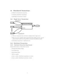
1-2 The Programmable Logic Design Process—An OverviewBecause the design phase isseparate from theimplementation phase, you candesign and simulate your systembefore choosing which PLDpart(s) you want to use.Steps for DesigningSystems withProgrammable LogicFigure 1-1 illustrates the typical design flow for synthesizingprogrammable logic.DesignDesign PhaseSimulateDefineConstraints &PrioritiesImplementationPhaseFit/PartitionSelectDeviceSimulatewithTimingProgramDeviceFigure 1-1 PLD Synthesis Design FlowLayoutthePCB
Steps for Designing Systems with Programmable Logic 1-3DesignYou can program all or any part of your design into PLD parts.To start, this means you need to define the functionality targetedfor PLDs as programmable logic in your schematic.Programmable logic takes the form of either:• programmable logic symbols, such as gates, flip-flops, shiftregisters, and counters, or• Design Synthesis Language (DSL) blocks, which describeprogrammable logic in a hardware description languageYour schematic can also include logic that is not targeted forPLDs. This is called non-programmable logic which takes theusual form of discrete parts.Your schematic can contain any combination of programmablelogic symbols, DSL blocks, non-programmable logic, and evenanalog parts.SchematicsExample: Your design might be alarge system which containsdiscrete PCB-level parts and oneor more PLDs. Or, it might be adesign of a reusable systemwhich you want to implemententirely in a PLD.SimulateYou can simulate your design before you know which PLDarchitectures (part types) you want to use. Before running thesimulation, <strong>PLSyn</strong> automatically compiles all of yourprogrammable logic into logic equations which are then used bythe simulator.Because simulations at this stage are before implementation,they do not include timing information. However, functionalsimulations can save a lot of time early in the design process,because the more time-consuming steps of optimization andfitting are not required until your design is finished.PSpice A/DPLogicProbe
1-4 The Programmable Logic Design Process—An Overview<strong>PLSyn</strong>See The <strong>PLSyn</strong> Features InYour Configuration on page xxiiifor more information.Example: You can place moreimportance on lower power thantotal priceSet Constraints and PrioritiesBy default, the <strong>PLSyn</strong> fitter considers every device in thelibrary. The number of devices you have available depends onthe design module options you have purchased.Before you begin the fitting/partitioning process, you canconstrain the parts that the <strong>PLSyn</strong> fitter considers by deviceproperties such as architecture, logic family, package type,speed, etc. This helps narrow the architecture-set from which<strong>PLSyn</strong> can choose, which results in faster completion of thefitting/partitioning process.You can also have <strong>PLSyn</strong> rank the solutions by defining therelative merit of device properties like price, number of pins,size, propagation delay, and frequency, before running the fitter.These are your solution priorities.<strong>PLSyn</strong>Note You must have thepartitioning feature to fit adesign into multiple devices.PartitioningOptionRequiredFit and PartitionAfter you have completed the functional design and set thefitting constraints and priorities, you are ready to fit yourprogrammable logic into PLD parts. Fitting is the process ofmapping a logic design into physical devices.<strong>PLSyn</strong> finds and displays a list of up to ten solutions whichimplement your design’s programmable logic while abiding toyour constraints. <strong>PLSyn</strong> lists the best solutions, ranked by yourassigned solution priorities.For each solution it finds, <strong>PLSyn</strong> displays the genericarchitecture, or template, for the device, along with its cost,speed, and power consumption.If your <strong>PLSyn</strong> package includes the partitioning feature, <strong>PLSyn</strong>automatically allocates or partitions logic into two or moredevices (up to a maximum of twenty). <strong>PLSyn</strong> can also partitionlogic between devices with different architectures. If so, <strong>PLSyn</strong>shows each architecture in the solution list.<strong>PLSyn</strong>’s fitting and partitioning process works automatically.You can also direct the process by using the physicalinformation file which contains statements in the Physical
Information Language (PIL). Using PIL, you can specify exactpart numbers, put groups of logic into specific devices, andspecify device pinouts.Steps for Designing Systems with Programmable Logic 1-5Select DeviceAfter the <strong>PLSyn</strong> fitter has found the solutions that implementyour design, the next step is to choose one of the architecturesand the corresponding physical part(s) you want to use.When you select an architecture in the solution list, <strong>PLSyn</strong>displays a list of all part numbers meeting the constraints youhave specified. These appear in the Solution Detail at the bottomof the <strong>PLSyn</strong> window. All you have to do is select which one(s)to use.<strong>PLSyn</strong>Simulate with TimingAny simulations that you perform after you have selected actualPLD part numbers, include timing information specific to thoseparts. This allows you to check the device’s timing within yoursystem and find potential problems such as setup/hold timeviolations or worst-case timing hazards which involve the PLDdevice.PSpice A/DPLogicProbeProgram DeviceAs the final step, you need to generate the fuse maps that yourdevice programmer needs to program the PLDs. <strong>PLSyn</strong>generates these as JEDEC files, one for each PLD device in yourimplementation.<strong>PLSyn</strong>
Primer: How to DefineProgrammable Logic2Chapter OverviewThis chapter guides you through the steps needed to synthesizea PLD device for a simple 3-to-8 decoder.Implementing a 3-to-8 Decoder with Programmable Logic onpage 2-2 describes the sample circuit.Design Phase: Defining Programmable Logic using SchematicSymbols on page 2-3 walks you through the steps needed toconvert existing schematic symbols to programmable logic.Implementation Phase: Fitting and Partitioning the Design onpage 2-5 walks you through the steps needed to fit, select andprogram a PLD device subject to the constraints and prioritiesyou define.Using a DSL Block to Define the Programmable Logic onpage 2-10 presents a way of defining the programmable logicthat is equivalent to that using schematic symbols.
2-2 Primer: How to Define Programmable LogicImplementing a 3-to-8Decoder withProgrammable LogicFigure 2-1 illustrates a simple 3-to-8 decoder, consisting ofthree 74LS04 inverters and eight 74LS11 3-input AND gates.Note You can mix bothprogrammable logic symbolsand DSL blocks on yourschematic.Figure 2-1 3-to-8 Decoder SchematicAssume that you want to target all of the decoder for PLDimplementation. You have two alternative but equivalentmethods from which to choose:• Convert discrete components to programmable logic usingschematic symbols.• Create Design Synthesis Language (DSL) blocks to definefunctionality using a hardware description language.
Design Phase: Defining Programmable Logic using Schematic Symbols 2-3In the remainder of this chapter, you will see how to use both ofthese methods. You will also learn how to set up and run thephysical implementation process, which is the same regardlessof how you specify the programmable logic.Design Phase: DefiningProgrammable Logicusing SchematicSymbolsBefore you beginCopy the following files from the \MicroSim rootdirectory\examples\plsyn\decoder directory to yourworking directory:decoder.schdecoder.stlschematic filestimulus library fileLoading and simulating the designTo load the schematic1 In the MicroSim program group, double-click theSchematics icon to start Schematics.2 From the File menu, select Open .3 Move to the directory containing decoder.sch.4 In the File Name list box, select the schematic file that youare interested in.
2-4 Primer: How to Define Programmable LogicOnce the circuit is loaded, you should run a simulation to ensurethat the circuit is working properly before you fit it into a PLD.The schematic is already configured to perform an 800 nsecsimulation.To simulate1 From the Analysis menu, select Simulate.Next you can view the results in Probe. This schematic has beenset up to start Probe automatically and to display the signalswhich have markers attached. The resulting signals shown inFigure 2-2 indicate that the decoder is in fact working correctly.Figure 2-2 Results of DecoderSimulationConverting 74LS Symbols toProgrammable LogicThere are two ways to enter programmable logic symbols, usingeither:• pre-defined programmable logic symbols found in thedig_prim.slb symbol library, or• 74xx symbols and then setting their IMPL attributes toPLSYN.Since the decoder is already defined with discrete logic, thesecond method (defining the IMPL attribute) is the mostconvenient way to turn the existing design into a PLD design.To include devices in the programmable logic1 Select all 74LS symbols on the schematic. Either:• draw a box around each symbol, or• S+click on each 74LS part.2 From the Edit menu, select Attributes.3 Click Yes to the prompt: Globally edit attributes of allselected items?
Implementation Phase: Fitting and Partitioning the Design 2-54 In the Attribute Name text box, type IMPL; in the Valuetext box, type PLSYN.This sets the value of the IMPL attribute to PLSYN for allselected parts that have an IMPL attribute (in this case, allparts).5 Click OK.Notice that the reference designator for each logic devicechanges to PLSYN_U1, PLSYN_U2, ..., and the color changesfrom green to blue, by default.As an alternative, you canchange each part individually(rather than globally) by doubleclickingeach 74LS device andsetting the value of each IMPLattribute to PLSYN.Note If you changed thedefault color settings, yourcolors may differ from thisexample.Verifying Functionality usingSimulationAt this point, you can re-run the simulation to verify that theprogrammable logic representation matches the discrete devicerepresentation. The programmable logic is compiled for youautomatically before the simulation starts.Implementation Phase:Fitting and Partitioningthe DesignAlthough you have just made theentire decoder designprogrammable logic, you canalso specify only a portion of adesign as programmable logic.It’s also easy to change a symbolback into a non-programmablelogic symbol. Just edit thesymbol’s IMPL attribute andclear its value so that it is blank.You are now ready to create the physical implementation. To dothis, you must run <strong>PLSyn</strong>.To activate <strong>PLSyn</strong>1 From the Tools menu, select Run <strong>PLSyn</strong>.<strong>PLSyn</strong> starts with the current design file loaded.
2-6 Primer: How to Define Programmable LogicSetting ConstraintsConstraints allow you to choose the types of devices into which<strong>PLSyn</strong> must fit the design. You can narrow the search forsolutions by selecting criteria such as device template(architecture), logic family, manufacturer, package type, power,speed, and temperature.By default, <strong>PLSyn</strong> considers all devices. Suppose you want tonarrow the solution search by selecting specific devicetemplates: P16V8A and P22V10.To constrain the solution to the P16V8A andP22V10 device templates1 From the Edit menu, select Constraints.<strong>PLSyn</strong> displays a list of constraints that you can enable.Some constraints, such as Device Template, also requirethat you select from a list of values.2 Click Devices.3 Click None to deselect all items.4 Scroll until P16V8A is visible and click on it.5 Scroll and find P22V10.6 Hold down the C key and click P22V10.7 Click OK.You can also constrain the device search by telling <strong>PLSyn</strong> tolook only for one logic family of devices. By default, all threelogic families—CMOS, ECL, and TTL—are included in thesearch.Suppose that you don’t want to use ECL.To exclude the ECL logic family from the solution1 Click Logic Families.2 Hold down the C key and click ECL. This leaves CMOS,OBS, and TTL highlighted.
3 Click OK to return to the constraints selection dialogbox.4 Click OK to exit constraints specification.Implementation Phase: Fitting and Partitioning the Design 2-7Setting PrioritiesSolution priorities allow you to determine the ranking of thesolutions found during the fitting and partitioning processaccording to factors such as price, speed, power consumption,and pin count. They also determine the ordering of alternatedevices for a given solution.By default, price has the highest priority.To indicate a preference for faster parts1 From the Edit menu, select Priorities.2 In the Prop Delay text box, type 10.3 In the Price text box, type 5.4 Click OK.Partitioning and FittingYou are now ready to start the fitting and partitioning process.During the fitting process, <strong>PLSyn</strong> finds and displays a list of upto 10 solutions which implement the programmable logicaccording to your constraints. <strong>PLSyn</strong> lists the best solutions,ranked according to solution priorities that you just assigned.To begin the fitting process1 From the Tools menu, select Fitter/Partitioner.<strong>PLSyn</strong> first checks the netlist to make sure that the design hasnot changed. Then <strong>PLSyn</strong> automatically compiles the design (ifnot already compiled), optimizes the design, and starts thefitting process.
2-8 Primer: How to Define Programmable Logic<strong>PLSyn</strong> scans the available file to find devices which match yourconstraints. <strong>PLSyn</strong> then searches for the devices which actuallyfit your design’s programmable logic. When this process iscomplete, <strong>PLSyn</strong> displays the solutions in the solution list at thetop of the <strong>PLSyn</strong> window.This design fits into either of the two templates which youselected earlier: P16V8A and P22V10. P16V8A is listed firstbecause it is the best device meeting the specified priorities.Further, the best P16V8A is a GAL16V8C-5LP, shown in thesolution detail list.To select a different part numberFor example, suppose you want to use a leadless chipcarrier,1 Click Browse to view the list of alternate parts.2 Select the PALCE16V8H-5JC/5.3 Click OK to keep the selection.The PALCE16V8H-5JC/5 is now the physical devicewhich implements the decoder (although a ratherexpensive implementation!).Verifying Timing Behavior usingSimulationIf you now simulate the design, the simulator includes thetiming specifications for the PALCE16V8H-5JC/5. Thisallows you to check the timing behavior for both:• the device itself, and• the device operating within your entire system.
Implementation Phase: Fitting and Partitioning the Design 2-9Creating Device ProgrammingFilesYou are now ready to run the Fuse Map Generator to create adevice programming file in JEDEC format.To generate fuse maps1 From the Tools menu, select Fuse Map Generator.<strong>PLSyn</strong> displays a warning message that no test vectors willbe included in the fuse map file at this time. For now, this isfine.2 Click Yes when prompted to continue.This creates a file named decoder.j1.To view the JEDEC file name and other usefulinformation1 Select Examine Doc File in the File menu.The JEDEC file is the input toyour device programmer.Alternatively, you could go backto the schematic and set theswitch to generate test vectors inthe <strong>PLSyn</strong> Setup dialog box (seepage 4-3), then re-simulate toinclude the test vector in theJEDEC file.Back Annotating the SchematicYou can now back annotate the schematic to include thephysical device(s) that you selected.To back-annotate the schematic1 In <strong>PLSyn</strong>, from the Tools menu, select Update Schematic.Schematics places the selected PLD(s) on a new schematic pagealong with the appropriate input/output ports.To view the PLD part as shown in Figure 2-31 In Schematics, from the Navigate menu, select Next Page.2 Click YES to the prompt: Save changes to current page?Figure 2-3 Back-AnnotatedSchematic Page
2-10 Primer: How to Define Programmable LogicPhysical implementation is thesame no matter how you set upthe programmable logic in yourschematic. If, after havingdefined the DSL block, you wantto implement the design, followthe instructions in Implementinga 3-to-8 Decoder withProgrammable Logic onpage 2-2.Using a DSL Block toDefine theProgrammable LogicThe following steps describe how to implement the 3-to-8decoder with a DSL procedure which is equivalent to theprogrammable logic symbols you used in the previous example.Before You BeginCopy the following files from the \MicroSim rootdirectory\examples\plsyn\decoder1 directory to yourworking directory:decoder1.schdecoder1.stlschematic filestimulus library fileLoading the DesignThe schematic file, decoder1.sch, contains only digitalstimulus and global output ports. The analysis setup is also preconfiguredto perform an 800 nsec simulation.To load the schematic1 From the File menu, select Open.2 Move to the directory containing decoder1.sch.3 In the File Name list, select the schematic file that you areinterested in.Figure 2-4 The decoder1.schExample Schematic
Adding a DSL BlockDSL blocks are simply hierarchical blocks which reference DSLsource code files instead of schematic files.Using a DSL Block to Define the Programmable Logic 2-11To add a DSL block1 From the Draw menu, select Block.2 Place one block on the schematic page between the inputsand the outputs, as shown in Figure 2-3.3 From the Draw menu, select Wire and connect eachstimulus input directly to the block.4 Repeat step 3 for each global output port, as shown inFigure 2-3. Each connection to the block creates a pin.a Rename the DSL block’s pins as shown in Figure 2-3:double-click the pin name (for example, P1) to bring upthe Change Pin dialog box.b Enter a new pin name.c Click OK.d Repeat steps a-c for each of the input and output pins.Figure 2-5 Connecting theDSL BlockDefining DSL Source CodeYou are now ready to enter the DSL source code for the block.Figure 2-6 Finished DSL BlockTo define DSL source code1 Double-click the block to push into it.2 Enter the DSL source code file, decod3x8.dsl, in theSetup Block dialog box, then click OK.Schematics displays the MicroSim Text Editor. Becauseyou are defining a new block, the PROCEDURE header and ENDstatements are defined for you as follows.PROCEDURE decod3x8( INPUT A, B, C;OUTPUT D0, D1, D2, D3, D4, D5, D6, D7);END decod3x8;
2-12 Primer: How to Define Programmable LogicNotice that the INPUT and OUTPUT nodes in the procedureheader correspond to the pin names of the DSL block.3 Type the entire TRUTH_TABLE statement between thePROCEDURE header and END statement as shown:This simple construct sets a single bit in the D7.. D0 outputbased on the three inputs’ integer value.4 From the File menu, select Save.5 From the File menu, select Close to exit the MicroSim TextEditor.To verify that the DSL version of the decoderperforms exactly as the logic symbol version1 From the Analysis menu, select Simulate.Equivalent Ways to Define theDecoder with DSLTry experimenting with the different features of DSL. Forexample, you could also implement the decoder using thefollowing CASE statement:CASE [C,B,A]WHEN 0 => [D7..D0] = 00000001b;WHEN 1 => [D7..D0] = 00000010b;WHEN 2 => [D7..D0] = 00000100b;
WHEN 3 => [D7..D0] = 00001000b;WHEN 4 => [D7..D0] = 00010000b;WHEN 5 => [D7..D0] = 00100000b;WHEN 6 => [D7..D0] = 01000000b;WHEN 7 => [D7..D0] = 10000000b;END CASE;Or, you could use the following (somewhat crude, but stilleffective) set of equations:D0 = /(A + B + C);D1 = A * /(B + C);D2 = B * /(A + C);D3 = A * B * /C;D4 = /(A + B) * C;D5 = A * /B * C;D6 = /A * B * C;D7 = A * B * C;With a little experimentation, you should find that DSL is botheasy-to-learn and powerful enough to describe complex blocksof logic.Using a DSL Block to Define the Programmable Logic 2-13
Designing withProgrammable Logic3Chapter OverviewThis chapter describes in detail how to specify programmablelogic using Schematics.The Different Ways to Specify Programmable Logic inSchematics on page 3-2 introduces the two equivalentmechanisms you can use to define programmable logic.Using Programmable Logic Symbols on page 3-2 describeswhere to find programmable logic symbols and how to convertdiscrete logic symbols to programmable logic.Using DSL Blocks on page 3-4 explains how to place and definefunctional blocks describing programmable logic using ahardware description language.Understanding Programmable Logic Nodes on page 3-13explains how to define the internal and interface nodesconnecting to programmable logic.<strong>Guide</strong>lines for Entering Programmable Logic on page 3-16, liststhe do’s and don’ts that you should follow to avoid problemsduring the physical implementation phase.The discussion in this chapterassumes that you are familiarwith Schematics, including theuse of hierarchical blocks. Referto your MicroSim SchematicsUser’s <strong>Guide</strong> for details on usingSchematics.
3-2 Designing with Programmable LogicThe Different Ways toSpecify ProgrammableLogic in SchematicsYou can define programmable logic in two ways using:• logic symbols (such as gates and flip-flops)• DSL (Design Synthesis Language) blocksYou can place programmable logic symbols and DSL blocksanywhere on your schematic—that means on any page and atany level of the hierarchy.Using ProgrammableLogic SymbolsNote IMPL is short for“implementation.”Logic symbols used as programmable logic have their IMPLattribute set to the value PLSYN. The available logic symbolsfall into two classes:• Generic logic symbolsExample: NAND4, JKFF• 74xx series symbolsExample: 74LS04 or 74HC107For a complete list of symbols,refer to the Programmable LogicSymbol Reference in <strong>PLSyn</strong>online help.Generic Logic SymbolsThe dig_prim.slb symbol library contains ready-to-useprogrammable logic symbols, including gates, enabled gates,flip-flops, and latches. Each symbol already has its IMPLattribute set to PLSYN.
74xx Series Logic SymbolsYou can also convert the common 74xx series logic symbolsfound in the 74xx.slb symbol libraries to programmable logic.To convert one 74xx series logic symbol toprogrammable logic1 Double-click the symbol.2 Click the IMPL= entry.3 In the Value text box, type PLSYN.4 Click Save Attr.5 Click OK.Using Programmable Logic Symbols 3-3To convert several 74xx series logic symbols toprogrammable logic all at once1 Select the 74xx symbols.2 From the Edit menu, select Attributes.3 Click Yes to the prompt: Globally edit attributes of allselected items?4 Click the IMPL= entry.5 In the Value text box, type PLSYN.6 Click Save Attr.7 Click OK.Schematics automatically updates the symbol’s referencedesignator and changes its color to blue (by default), to showthat it is programmable logic.Note Some of the 74xx symbols cannot be converted toprogrammable logic. These symbols do not havethe IMPL attribute. Adding an IMPL attribute willnot work because <strong>PLSyn</strong> does not know thesymbol’s logic function.Figure 3-1 7400 Symbol asProgrammable Logic
3-4 Designing with Programmable LogicYou can also change programmable logic symbols back todiscrete PCB devices.To revert to non-programmable logic1 Select the symbol(s) and bring up the Edit Attributes dialogbox as described in the above two procedures.2 Click the IMPL= entry.3 Clear (set to blank) the Value text box.4 Click Save Attr.5 Click OK.Using DSL BlocksThis section describes how todefine and edit DSL blocks withinSchematics. For information onDSL language syntax, refer tothe PIL Reference in <strong>PLSyn</strong>online help.Note DSL files must have the.dsl extension.In addition to logic symbols, you can define programmable logicusing DSL (Design Synthesis Language) blocks on yourschematic.What Are DSL Blocks?DSL blocks are hierarchical blocks which have a languagebaseddefinition instead of a symbolic definition. DSL logicexpressions and constructs take the place of discrete logicsymbols. So, instead of referencing a schematic file (.sch),DSL blocks reference a DSL source code file (.dsl).
Using DSL Blocks 3-5What Are DSL Procedures?Each DSL block you place corresponds to a single procedurewithin the source code file. Procedures contain languageconstructs such as simple logic expressions, truth-tables, orstate-machine definitions. The signals coming into the DSLblock define the inputs to the procedure. Likewise, the outputsof the procedure define the output signals of the DSL block.A DSL block has a PLMODEL attribute which defines theprocedure name.Example: The HB1 DSL block shown in Figure 3-2 referencesthe adder5.dsl DSL source code file which contains theADDER5 procedure referenced by the block’s PLMODELattribute.DSL blockadder5.dslPROCEDURE ADDER5( INPUT A[4..0], B[4..0];OUTPUT SUM[4..0]);SUM = A .+. B;END ADDER5;Figure 3-2 Relation of PLMODEL Attribute and DSLProcedure Name
3-6 Designing with Programmable LogicCreating a DSL Block in YourSchematicYou can change the size of theblock by selecting the block, thenusing S right-click on oneof the corners to drag it to thedesired size.Note Pin names must not beone of the DSL keywords,such as INPUT or OUTPUT.For the list of DSL keywords,refer to the DSL Reference in<strong>PLSyn</strong> online help.The ERC attribute defines theelectrical purpose of the pin.Note The .dsl file cannothave the same name as theschematic file. (It is reservedfor system use.) For example,a schematic nameddecoder.sch cannot referencea file named decoder.dsl.To create a DSL block1 In Schematics, from the Draw menu, select Block.2 Click to place the block on the schematic page.3 Connect wires or buses directly to the block. Eachconnection automatically creates a pin at the junction.4 Define the names and types of each pin.a Double-click the pin name.b Enter a new pin name.When naming a bus connection, use the Schematics buslabel syntax, for example, A[4-0].c If necessary, select the correct ERC value for the pin.By default, the pins on the left are given an ERCattribute of input and pins on the right are given anERC of output. Do not set the ERC attribute to DON’TCARE; this is not allowed for a DSL block.5 Push into the DSL block. Either:• double-click the block, or• from the Navigate menu, select Push.Because this is a new block, you are prompted for the nameof the file containing the DSL source code.6 Enter the name of the DSL source file (using the .dslextension) that you want to create or reference.
Using DSL Blocks 3-77 If you have not yet created the DSL procedure for this block,then do one of the following:• If the DSL file does not exist, Schematics activates theMicroSim Text Editor automatically. Specify the newDSL procedure and save the .dsl file.• If the DSL file does exist but you still need to specifythe procedure, activate the MicroSim Text Editor fromthe MicroSim program group, open the .dsl file,specify the new DSL procedure, and save the file.See the next section for information on defining DSLprocedures.Using the MicroSim Text Editorto Define DSL ProceduresWhen given a file name with the .dsl extension, Schematicsdisplays the MicroSim Text Editor which you can use to:• Define the body of the DSL procedure.• Add other procedures or functions.For new DSL procedures, Schematics automatically creates aprocedure template with input and output ports corresponding tothe DSL block’s pin names and attributes.Figure 3-3 The DSL Procedure Template
3-8 Designing with Programmable LogicIf the block’s PLMODEL attribute is undefined, Schematicsdefines it for you using the DSL file name (excluding the .dslextension).Schematics also automatically translates the bus label format tothe DSL array format.Example: In the procedure header shown in Figure 3-3, the busformat A[4-0] is translated to the array format A[4..0].Changing the DSL BlockInterfaceThe pins on the DSL block must match the number, name, andsignal direction of the port nodes used in the DSL procedure.This means that if you add or delete pins, or change the width ofa bus on your DSL block, you must update the procedure’s portnodes corresponding to the changed pins.Example: If you change a port’s direction from an output to aninput, you must change the ERC value of the correspondingDSL block pin to INPUT.
Using DSL Blocks 3-9To change the pin properties in Schematics1 In Schematics, double-click the pin name in the DSL block.2 Change values in the Pin Name text box or Pin Attibutesframe as needed.To change the pin properties in the MicroSim TextEditor1 In Schematics, double click the DSL block.2 Modify the procedure header to match the new interface.Using Existing DSL Source CodeYou can create a DSL file ahead of time and then associate itwith any DSL block you create thereafter.To associate an existing DSL file with a new DSLblock1 Check the port node names in the DSL procedure you planto use with the new DSL block.2 Place a block.3 Add a pin for each of the port nodes in the DSL procedure.4 For each pin, change its name and ERC (if needed) to matchthe corresponding port node in the DSL procedure.5 Add a PLMODEL attribute to the block and assign the DSLprocedure’s name as its value.a Select the DSL block.b From the Edit menu, select Attributes.cIn the Name text box, type PLMODEL.In the Value textbox, type the DSL procedure name.For detailed instructions (menuoptions and mouse moves), seethe following procedures:• To create a DSL block onpage 3-6.• To change the pin propertiesin Schematics on page 3-9.
3-10 Designing with Programmable Logicd Click Save Attr.e Click OK.6 Push into the block, and when prompted, enter the name ofthe existing DSL source code file.Structuring DSL Source FilesWhen organizing your DSL procedures, you can have• one procedure per file, or• multiple procedures per file.Example: A single DSL procedure in each fileIn Figure 3-4, if you were to make a change only to file2.dsl,file1.dsl is not recompiled.SchematicpageDSLBlockDSLBlockfile1.dslPLMODEL=Afile2.dslPLMODEL=file1.dslPROCEDURE A( INPUT ...; OUTPUT ... );...END A;file2.dslPROCEDURE B( INPUT ...; OUTPUT ... );...END B;Figure 3-4 A Source Code File for Each DSL Block
Using DSL Blocks 3-11Example: More than one DSL procedure in asingle fileFrom a maintenance point of view, this method is easier tomanage because there are fewer files.SchematicpageDSLBlockDSLBlockfile3.dslPLMODEL=Afile3.dslPLMODEL=Bfile3.dslPROCEDURE A( INPUT ...; OUTPUT ... );...END A;PROCEDURE B( INPUT ...; OUTPUT ... );...END B;Figure 3-5 Single DSL Source Code File with More Than OneProcedure
3-12 Designing with Programmable LogicFor information on the use of theINCLUDE and USE statements,refer to the DSL Reference in<strong>PLSyn</strong> online help.To create a pre-compiled DSLfile, manually compile the filefrom <strong>PLSyn</strong> using CompileLibrary from the Tools menu.Calling DSL Procedures andFunctions from within aProcedureLike other programming languages, DSL allows a procedure tocontain calls to other procedures and functions.You must define called procedures and functions before they arecalled from the main DSL procedure. There are several ways todo this:• Add the called procedure or function directly to the sourcecode before the calling procedure.• Include another DSL source file into your source before thecalling procedure by using the INCLUDE statement.• Reference a pre-compiled DSL file (for example, a libraryof commonly used DSL procedures) from your source byusing the USE statement before the calling procedure.
UnderstandingProgrammable LogicNodesAs you enter a programmable logic design, the nodes whichconnect to programmable logic symbols or DSL blocks are oftwo types.Understanding Programmable Logic Nodes 3-13Internal nodes These connect programmable logic toother programmable logic.Interface nodes These are at the boundary of theprogrammable logic, and connect to all other schematicsymbols, such as global ports, non-programmable logic, andanalog devices.After you have performed the physical implementation of yourdesign, interface nodes correspond to physical pins on a PLD.Labeling NodesYou are not required to label the programmable logic nodes inSchematics. Schematics automatically generates a unique name,such as NPL_0013.However, to reference a node in your design’s PhysicalInformation (.pi) file, you should label the node so that you’llknow how to refer to it. Once labeled, <strong>PLSyn</strong> carries the namethroughout the physical implementation process by <strong>PLSyn</strong>.To label any node1 Double-click the wire.2 Enter a name.For more information on the .pifile, see Chapter 6, Controllingthe Fitting Process Using the.pi File and refer to the PILReference in <strong>PLSyn</strong> online help.
3-14 Designing with Programmable LogicFor a listing of DSL keywords,refer to the DSL Reference in<strong>PLSyn</strong> online help.Node naming restrictionsProgrammable logic node names must adhere to the followingnaming conventions:• The first character must be alphabetic (a-z, or A-Z).• Remaining characters can be any combination of alphabetic(a-z, A-Z), numeric (0-9), and underscore (_) characters.• Names cannot be any of the DSL keywords.Node names are case-insensitive which means upper-case andlower-case letters are treated alike.Labeling interface nodesFor interface nodes, you can insure that the node label willpersist with the PLD implementation.For more information, see BackAnnotating the Schematic onpage 2-9.To force the label to appear in the back-annotatedPLD symbol1 Attach a global port to the interface node, as shown inFigure 3-6.2 Label the global port.Non-programmablelogicProgrammablelogicFigure 3-6 Programmable Logic Interface Node Labeled witha Global Port
Creating Active-Low InterfaceNodesUnderstanding Programmable Logic Nodes 3-15To create active-low inputs or outputs to yourprogrammable logicPlace a LOW_TRUE port (instead of a global port).Note The LOW_TRUE port creates interface nodes inthe same manner as the global port. Therefore,you cannot use the LOW_TRUE port to createactive-low internal nodes.The LOW_TRUE port symbol iscontained in the dig_prim.slbsymbol library.Converting Internal Nodes toInterface NodesWhen <strong>PLSyn</strong> runs an optimization, internal programmable logicnodes are automatic candidates for removal known as nodecollapsing. To avoid this, you can change an internal node to bean interface node, and have the node appear at a physical PLDpin.You could use this method tomake an internal node availablefor testing. See Figure 3-6 onpage 3-14 for an example.To convert an internal node to an interface node1 Attach a global port.2 Assign a label.Creating Physical NodesTo create a physical node at the schematic levelPlace the PHYNODE/PL symbol and connect it to a wire.For more information on physicalnodes, refer to the DSLReference in <strong>PLSyn</strong> online help.
3-16 Designing with Programmable LogicThe LO and HI symbols arecontained in the port.slbsymbol library.Assigning a Logic 0 or 1 to anInputYou can assign constant 0 or 1 to a programmable logic symbolby using the LO and HI symbols in one of the ways describedbelow.Alone If you attach a LO or HI symbol directly to an inputpin of a programmable logic symbol (or to an unlabeled wireconnected to an input pin), <strong>PLSyn</strong> treats that input as a logicconstant 0 or 1.Example: Use the HI symbol to tie an unused input on an ANDgate high, or to tie the J and K inputs of a flip-flop high to createa T flip-flop.Attached to an interface node If a LO or HI symbolis attached to an interface node, the LO or HI behaves like astimulus during simulation. <strong>PLSyn</strong> still creates a physical devicepin.<strong>Guide</strong>lines for EnteringProgrammable LogicDo this• Always begin the names of the following objects with analphabetic character (a-z or A-Z):• Schematic (.sch) and DSL source (.dsl) file names• Programmable logic interface and internal nodes• DSL block pinsThe remainder of the name can contain numbers (0-9) orthe underscore (_).
NoteDo not use any other punctuation characters in thename.• Make sure that each independent collection ofprogrammable logic has at least one input interface and oneoutput interface node. That is, at least one input and oneoutput signal must connect either to a global port or to nonprogrammablelogic.<strong>Guide</strong>lines for Entering Programmable Logic 3-17Don’t do this• Label any programmable logic node (interface or internal)the same as any of the DSL keywords. For example, you canuse OUT, but not OUTPUT.• Tie output interface nodes together. That is, the same nodemay not be driven by two or more programmable logicoutput pins.• Connect the analog ground node (node 0) to anyprogrammable logic interface. Use the digital constantsources LO and HI instead.• Make a port label an integer.• Use punctuation marks (except for underscore characters) innames. See Do this above for naming conventions.• Name the DSL file or procedure the same name as any of theprogrammable logic symbols contained in digprim.slb.For a listing of DSL keywords,refer to the DSL Reference in<strong>PLSyn</strong> online help.
Simulating ProgrammableLogic Designs4Chapter OverviewThis chapter describes how to simulate your programmablelogic design both before and after PLD implementation. Topicsinclude:Introduction to Simulating with PLogic or PSpice A/D onpage 4-2Setting Up Simulations on page 4-3Starting Simulations on page 4-4How the Simulator Uses Programmable Logic I/O Models onpage 4-5Simulating with Timing on page 4-6Generating Test Vectors on page 4-6Using Probe Markers on page 4-10For more information on PSpiceA/D, refer to your MicroSimPSpice A/D User’s <strong>Guide</strong>.
4-2 Simulating Programmable Logic DesignsIntroduction toSimulating with PLogicor PSpice A/DOnce you have entered a design which includes programmablelogic, you can simulate both before and after you have chosen aphysical implementation. The purpose of the simulationdepends on the development stage of your design.Verify function before implementation At thisstage, simulations do not include timing. Instead, this is a goodtime to verify that your design is behaving as you expect it tooperate.Verify timing after implementation At this stage,after having selected the PLD devices, simulationsautomatically include timing information for the devices such aspropagation delays and setup times. You can verify not only thetiming of each PLD, but also the timing of the entire circuitincluding the PLD(s).
Setting Up SimulationsSimulation setup for circuits containing programmable logic issimilar to that for any other circuit. The way you navigate to thesetup options depends on which simulator you have: PLogic orPSpice A/D.Setting Up Simulations 4-3Displaying the Dialog Box forSimulation SetupPLogic simulation setupIf you have PLogicTo display the Analysis Setup dialog box1 In Schematics, from the Analysis menu, select Setup.If you have PSpice A/DTo display the Digital Setup dialog box1 In Schematics, from the Analysis menu, select Setup.2 Click Digital Setup.PSpice A/D simulation setup
4-4 Simulating Programmable Logic DesignsRefer to your MicroSim PSpiceA/D User’s <strong>Guide</strong> for detailedinformation on how to specify thedelay, A/D interface level(PSpice A/D only), and flip-flopinitialization for your design as awhole.Note The power and groundnodes and the A/D interfacesettings only apply to mixedsignalsimulations withPSpice A/D. These optionshave no effect on digital-onlysimulations.Defining Simulation SetupOptions for Programmable LogicBesides the usual simulation setup options, you can also specifysimulation setup specific to the programmable logic part of yourdesign. This includes options for delay, A/D interface level, andpower supplies.To display the dialog box for programmable logicsettings1 From within the simulation setup dialog box, clickAdvanced.In addition to the usual settings for the simulator, you can enablethe capture of test vectors for the fuse map (JEDEC) file. SeeGenerating Test Vectors on page 4-6 for more information.Starting SimulationsThere are two ways to start a simulation, either fromSchematics, or from the simulator (PSpice A/D or PLogic).Using Schematics, the netlister generates a netlist and compilesthe programmable logic. Although you can run simulations oncircuit files previously generated by Schematics, they might notreflect the current state of your design. To insure that what youare simulating is always in sync with your schematic design, werecommend that you always start your simulations fromSchematics.
To start a simulation from within SchematicsSelect Simulate in the Analysis menu.How the Simulator Uses Programmable Logic I/O Models 4-5How the Simulator UsesProgrammable Logic I/OModelsI/O models define the digital and analog characteristics ofdigital input and output pins. As with all other digital devices,your programmable logic also uses I/O models. If a digital pin isconnected to other digital devices, the simulator refers to the I/O model to obtain the pin’s output resistance, as well as its inputor output capacitance.If your package includes PSpice A/D, you can simulate analogdevices along with your programmable logic. If a digital pin isconnected to analog devices, PSpice A/D refers to the I/O modelto obtain the name of an interface subcircuit (either AtoD orDtoA) to insert between the devices.When you simulate programmable logic, the simulator attemptsto use the I/O model appropriate for the technology. Table 4-1lists the I/O models used by PSpice A/D and PLogic forprogrammable logic.The simulator determines the correct technology if:• You have constrained the physical implementation to onetechnology.• The fitting process is complete and you have selected PLDpart numbers.If the simulator cannot determine the technology of theprogrammable logic (for example, you have selected two ormore technologies in your device constraints), the simulatoruses IO_DEFAULT_PLSYN, which has 74LS characteristics.Table 4-1 <strong>PLSyn</strong> I/O ModelsI/O Model Name*PLSYN_IO_DEFAULTPLSYN_IO_TTLPLSYN_IO_CMOSPLSYN_INT_IO_ECLPLSYN_EXT_IO_ECL* These models are located inthe dig_io.lib symbol library.
4-6 Simulating Programmable Logic DesignsNoteIf your design is partitioned into two or moredevices, the simulator automatically uses theappropriate I/O model at the logical boundaries ofeach device.Simulating with TimingFor more information on howPSpice A/D treats unspecifiedpropagation delays, refer to yourMicroSim PSpice A/D User’s<strong>Guide</strong>.After you have performed the physical implementation andselected PLD devices, any simulations that you run will includetiming information for those devices. This timing information isobtained from <strong>PLSyn</strong>’s device library. The simulator uses thesetiming values:t PDcombinatorial propagation delayt COclock-to-output propagation delaysetup timet SThe device library contains maximum-rated values for t PD andt CO , and minimum values for t S . The simulator calculatesminimum and typical values from the maximum propagationdelay values.Generating Test VectorsIn the <strong>PLSyn</strong> context, the term test vectors refers to the sectionof the JEDEC file used by device programmers to validate thedevice after it has been programmed. Each line of the JEDECfile’s test vector section contains input signals (which stimulatethe programmable logic) and the expected output signals.Device programmers apply the input signals and compare theresults to the expected outputs specified in the JEDEC file.
Generating Test Vectors 4-7Enabling Test Vector GenerationIf you enable test vector generation during the simulation,<strong>PLSyn</strong> collates and formats the input and output signals for eachPLD in the solution into test vectors. <strong>PLSyn</strong> adds these vectorsto the JEDEC file(s) when the fuse map is created after you havefitted and performed device selection.If you have PLogicTo enable test vector generation1 In Schematics, from the Analysis menu, select Setup.2 Select (✓) the Capture Test Vectors check box.If you have PSpice A/DTo enable test vector generation1 In Schematics, from the Analysis menu, select Setup.2 Click Digital Setup.3 Select (✓) the Capture Test Vectors check box.How the Simulator RespondsWith test vector generation enabled, the programmable logicportion of the design runs in unit delay mode. This avoids testvector mismatches during device programming.Note Any time you re-fit or select a different solution, youmust re-simulate in order to generate the testvectors for the new device(s).Unit delay mode effectively turnsoff the simulator’s inertial delaybehavior which causes shortpulses to be swallowed.Because device programmersdo not support inertial behavior,this helps avoid test vectormismatches.
4-8 Simulating Programmable Logic DesignsSee page 4-3 for information onhow to get to the setup dialogbox for your simulator.Using the “Sample Window”ControlThe Sample Window value (specified in the simulation setupdialog box) defines the interval during which the simulatorconsiders input changes to occur at the same time.Set this value when signals, considered part of the same inputvector, arrive at the boundary of the programmable logic atslightly different times. This is useful, for example, in mixedanalog/digital designs.Example: How the SimulatorCreates Test VectorsCase 1Consider the following case,I1I212PLSYN_U13O1AND2with inputs and outputs as follows.Table 4-2 Test Vectors forCase 1Time SampleTakenI1 I2 O110 0 0 L11 1 0 L20 1 1 H30 0 1 LNote In JEDEC files, 0, and 1are input values; L and H areoutput values.I1I2O10 10 20 30With Sample Window set to zero, the simulator creates testvectors by recording the value of all inputs and outputswhenever any input changes. The vector consists of all priorinput values, along with the current output value. In other words,the simulator assumes that any input change propagates to theoutput by the time the next input change occurs. Table 4-2shows the test vectors that the simulator creates using this logic.
Generating Test Vectors 4-9The simulator takes one final sample at the end of thesimulation. As you can see, these test vectors are correct, eventhough the input changes do not arrive simultaneously.Case 2Unfortunately, this approach produces the wrong results in thefollowing case,I1I212PLSYN_U23O1OR2with inputs and outputs shown below.I1I2O10 10 20 30With Sample Window set to zero, the simulator produces thevectors shown in Table 4-2. At time 11, the output value of L isincorrect. The result of I1 changing to 1 had not yet propagatedto the output.Corrected Case 2The sampling window allows you to treat staggered inputs as ifthey had arrived simultaneously. A sampling window beginswhen any input changes and ends after the sample time expires.The inputs in the test vector consist of the input values at the endof the sampling window.In case 2, a sampling window at least 1 unit in the duration,corrects the problem.Table 4-3 Test Vectors forCase 2Time SampleTakenI1 I2 O110 0 0 L11 1 0 L20 1 1 H30 0 1 HTable 4-4 Test Vectors forCorrected Case 2I1I2O10 10 20 30Time SampleTakenI1 I2 O110 0 0 L20 1 1 H30 0 1 H
4-10 Simulating Programmable Logic DesignsTable 4-2 shows the test vectors.Troubleshooting Test VectorDifferencesSometimes, when the device programmer tests the device, theresults produced by the part are different from the expectedoutput results produced by the simulator. If this occurs, thefollowing hints can help you solve the problem.• Try specifying a non-zero sampling window as described inthe previous section. Use a value greater than thepropagation delay (t min ) of the device.• Make sure that the initial value of the clock stimulus isinactive for the type of flip-flop you are using. Why? In thesimulator, the flip-flop primitive requires the entire clockedge (for example, 0 → 1) to register the data. However, inthe programmer, the flip-flop registers its input if the firstvector contains a value of 1 for the clock.Using Probe MarkersTo view logic levels, you can place markers on bothprogrammable logic interface nodes and nodes internal to theprogrammable logic in the schematic. If you’ve configured yoursystem to automatically run Probe after simulation, waveformresults immediately display in the Probe window.Collapsed nodes happen when<strong>PLSyn</strong> removes an internalsignal node by substituting thenode’s equation into anyequation that references thenode.A caution about collapsed nodesWhen optimizing a design, <strong>PLSyn</strong> reduces the logic equationswhich can result in collapsed nodes. Collapsed nodes are notavailable in Probe, even if you have placed markers on them.Note Results at interface nodes are still available.
Creating the PhysicalImplementation5Chapter OverviewThis chapter describes how to create the physicalimplementation of your programmable logic using <strong>PLSyn</strong>.Overview of the Physical Implementation Process on page 5-3reviews the steps you must follow to implement theprogrammable logic.Where to Find Status and Design Information on page 5-4 talksabout the log and document files that <strong>PLSyn</strong> generates.Activating and Loading <strong>PLSyn</strong> on page 5-5 explains how toactivate <strong>PLSyn</strong>.Compiling the Logic on page 5-7 explains how <strong>PLSyn</strong> convertsthe programmable logic symbols and DSL blocks to logicequations.Optimizing the Logic Equations on page 5-10 describes thekinds of algorithms <strong>PLSyn</strong> uses to reduce the logic equations.Overview of Fitting and Partitioning Logic on page 5-14explains how to run the <strong>PLSyn</strong> fitter and how it works.
5-2 Creating the Physical ImplementationLimiting the PLD Parts Available for Search on page 5-16explains how to use the available file to specify a preferreddevice set.Constraining Devices on page 5-18 explains how to narrow thesearch by manufacturer, logic family, speed, and/or part type.Prioritizing the Solutions on page 5-23 explains how to use<strong>PLSyn</strong> to rank the solution set by speed, cost, powerconsumption, and pin count preferences.Running the <strong>PLSyn</strong> Fitter and Partitioner on page 5-25 explainshow to start the <strong>PLSyn</strong> fitter.Selecting Devices on page 5-26 explains how you can select adifferent device from the solution list.Creating Fuse Maps on page 5-27 explains how to generate fusemaps to program the devices.Updating the Schematic on page 5-28 explains how to backannotatethe schematic with the selected PLD implementation.Creating PCB Netlists on page 5-29 provides tips whenpreparing to generate a netlist for board layout.When You Change the Design on page 5-30 provides tips whentrying iterative what-if implementations.
Overview of the PhysicalImplementation ProcessAfter you have described your design in Schematics, you areready to create the physical implementation of yourprogrammable logic using <strong>PLSyn</strong>.To have <strong>PLSyn</strong> determine solutions for thephysical implementation automatically1 If needed, customize the available file (.avl) with userdefinedproperties that you want to constrain.2 Define the selection constraints using Constraints in the Editmenu.3 Define the solution priorities using Priorities in the Editmenu.4 Run the <strong>PLSyn</strong> fitter using Fitter/Partitioner from the Toolsmenu. <strong>PLSyn</strong> automatically compiles and optimizes theprogrammable logic in your design.5 Select the PLD device(s) you want to use.6 Create the fuse maps using Fuse Map Generator in the Toolsmenu.7 Back-annotate the schematic with the PLD device(s) usingUpdate Schematic in the Tools menu.Overview of the Physical Implementation Process 5-3
5-4 Creating the Physical ImplementationSee Compiling the Logic onpage 5-7 and Optimizing theLogic Equations on page 5-10for more information on what<strong>PLSyn</strong> does when compiling andoptimizing your design.For more information on theusing the .pi file, refer toChapter 6,Controlling theFitting Process Using the .pi Fileand the PIL Reference in <strong>PLSyn</strong>online help.For MACH devices, <strong>PLSyn</strong> alsoproduces a report file. For moreinformation, see The MACHReport File on page 8-52.If You Want More ControlAs described above, you can leave the synthesis details to<strong>PLSyn</strong>. But if you want more control, you can:• Manually run the <strong>PLSyn</strong> compiler.• Manually run the <strong>PLSyn</strong> optimizer.• Direct the fitting/partitioning process by specifying controlsin the physical implementation file (.pi).Where to Find Statusand Design InformationTo document your design, or, if your design fails to fit, <strong>PLSyn</strong>furnishes tools that can help you solve any problems:Message Viewer The Message Viewer displays warningsand error messages that occur when <strong>PLSyn</strong> (or anotherMicroSim program) encounters a problem. You can access helptext that relates directly to each message. For some messages,you can also jump to the point in your design where the problemwas detected.Log file The log file (design_name.log) contains statusand error messages from each of the implementation processes.For a detailed description ofdocumentation file contents, seeAppendix A, TheDocumentation File.Documentation file The documentation file(design_name.doc) contains detailed information about yourdesign, such as the logic equations and device pinouts. <strong>PLSyn</strong>automatically creates this file after the optimization phase, andupdates this file after you generate the fuse map file(s).
Activating and Loading <strong>PLSyn</strong> 5-5Activating and Loading<strong>PLSyn</strong>This section describes how to:• Start <strong>PLSyn</strong>.• Load a design.• Interpret the <strong>PLSyn</strong> window.Activating <strong>PLSyn</strong>Start the <strong>PLSyn</strong> program either from:• Schematics, or• the <strong>PLSyn</strong> program icon in Windows.From SchematicsTo activate <strong>PLSyn</strong> from Schematics1 In the Schematic Editor, from the Tools menu, select Run<strong>PLSyn</strong>.If your design is already open in Schematics, then you can startthe physical implementation phase of your design once the<strong>PLSyn</strong> main window displays. If not, you must load a designdirectly into <strong>PLSyn</strong> as described in Loading a Different Designon page 5-6.From the Windows Program ManagerIn the Windows program manager, there is a program group thatcontains Windows icons for all installed MicroSim programs,including <strong>PLSyn</strong>.
5-6 Creating the Physical Implementationdouble-clickthis iconTo activate <strong>PLSyn</strong> from the Windows ProgramManager1 In the MicroSim program group, double-click the <strong>PLSyn</strong>icon.<strong>PLSyn</strong> activates without a design. See Loading a DifferentDesign for further instructions.Loading a Different DesignOnce you have activated <strong>PLSyn</strong>, you can change to a differentdesign at any time.To load an existing design1 From the File menu, select Open.2 Select a schematic (.sch) or DSL source (.dsl) file.Solution ListSolution Detail ListFigure 5-1 Main <strong>PLSyn</strong>WindowThe <strong>PLSyn</strong> Main WindowOnce loaded, <strong>PLSyn</strong>’s main window appears as shown inFigure 5-1.The top area, called the solution list, displays architectureschosen by the <strong>PLSyn</strong> fitter. The bottom area, called the solutiondetail list, displays a list of alternative part numbers availablefor the architecture you selected in the solution list above.During fitting, this window contains a list of the devicetemplates <strong>PLSyn</strong> is considering.
Compiling the Logic 5-7Compiling the LogicThe <strong>PLSyn</strong> compiler converts all of your design’sprogrammable logic (logic symbols and DSL blocks) intoequivalent logic equations. <strong>PLSyn</strong> writes the compiled logic toan internal file named design_name.afb which thesimulator and the <strong>PLSyn</strong> optimizer use later on.You can compile programmable logic at different stages ofdesign development:• Automatically during the fit and partition process.• Manually to verify the syntax of the programmable logic.• Manually to compile DSL files that include the USEstatement to reference other DSL files—also known as alibrary compile.Note You must manually compile DSL files that containthe USE statement before running a generalcompilation of your design, or before starting the fitand partition process. This is explained in moredetail in the following two sections.For more information on fittingand partitioning, see Overviewof Fitting and Partitioning Logicon page 5-14 and the sectionsthat follow.Manually Compiling LogicTo manually compile all programmable logic inyour design1 Pre-compile any DSL files that include the USE statement(see Compiling DSL Libraries on page 5-8).2 From the Tools menu, select Compiler.To ensure that the schematic matches the <strong>PLSyn</strong> database,<strong>PLSyn</strong> first checks to see if any of the programmable logic, orits interfaces, has changed since the last generated netlist. If theprogrammable logic portion of your design has changed, <strong>PLSyn</strong>automatically regenerates the netlist.Another way to automaticallycompile the programmable logicis as follows:1 In Schematics, from theAnalysis menu, select CreateNetlist.
5-8 Creating the Physical ImplementationCompiling DSL LibrariesWhenever your design includes DSL blocks that include theUSE statement, you must load each DSL file and run a librarycompile before any other manual or automatic compilations takeplace.To compile DSL blocks that include the USEstatement1 From the File menu, select Open, and then select the nameof the DSL file you want to compile.2 From the Tools menu, select Compile Library.Responding to Compile-TimeStatus and ErrorsDuring compilation, <strong>PLSyn</strong> displays a status window whichshows the compiler’s progress. You can abort the compilation atany time.To abort the compilation1 In the status window, click Cancel.If there are compile-time errors, <strong>PLSyn</strong> displays the messages inthe Message Viewer. In addition, <strong>PLSyn</strong> keeps a written log.To control whether <strong>PLSyn</strong> writes compiler errorsto the log fileDo the following before starting the compile:1 From the Tools menu, select Options.2 Select (✓) the Output Warnings check box.3 Click OK.After you have corrected any errors in your DSL blocks, youmust restart the compiler.
Compiling the Logic 5-9Controlling Node GenerationDuring CompilationYou can control whether the <strong>PLSyn</strong> compiler creates internalnodes for carry bits for arithmetic and relational operators.To allow <strong>PLSyn</strong> to create internal nodesDo the following before starting the compile:1 From the Tools menu, select Options.2 Select (✓) the Create Nodes check box.3 Click OK.Resolving “Out of Memory”ConditionsIf you encounter an “Out of Memory” message, you can reducememory requirements by setting the maximum number ofproduct terms any equation form can have.To limit the number of product termsDo the following before starting the compile:1 From the Tools menu, select Options.2 In the Product Term text box, type an integer value for themaximum number of allowed product terms ranging from64 to 5012. The default is 1024.3 Click OK.As a rule of thumb, lower the Product Term value by a factor oftwo. If you continue to get an “Out of Memory” message, lowerthe value again.
5-10 Creating the Physical ImplementationNote Optimization is onlyneeded prior to fitting andpartitioning, not prior torunning simulations.For more information on fittingand partitioning, see Overviewof Fitting and Partitioning Logicon page 5-14 and the sectionsthat follow.If you experience an “Out ofMemory” message, try limitingthe maximum number of productterms allowed in an equationform and restart the optimization.For more information, seeResolving “Out of Memory”Conditions on page 5-9.Optimizing the LogicEquations<strong>PLSyn</strong> performs optimization prior to fitting to compact yourdesign’s programmable logic into as few equations and nodes aspossible. This allows your design to fit into the fewest andsmallest possible devices.<strong>PLSyn</strong> writes the optimizer output to a file nameddesign_name.fb which the fitter and partitioner use later on.Though you would usually have <strong>PLSyn</strong> run the optimizerautomatically in the fit and partition process, you can alsomanually run the optimizer.To manually optimize all programmable logic inyour design1 Make sure your design is compiled (see Compiling theLogic on page 5-7).2 From the Tools menu, select Optimizer.During optimization, <strong>PLSyn</strong> displays a status window whichshows the optimizer’s progress. You can abort the optimizationat any time.To abort the optimization1 In the status window, click Cancel.
How the <strong>PLSyn</strong> OptimizerSynthesizes Logic EquationsIn addition to compacting the logic, the optimizer also producesmultiple, functionally-equivalent equation sets to accommodatethe wide variety of device architectures available on the market.This means that for each potential device solution, the <strong>PLSyn</strong>fitter is able to select the set of equations that best uses thecharacteristics of that particular architecture.The optimizer employs several techniques to synthesize theequations.Optimizing the Logic Equations 5-11DeMorganization DeMorganization allows the <strong>PLSyn</strong>fitter to invert signals internal to a device while maintaining thesignal polarity and functionality as described by the logicdesign. The ability to tailor equations internally to the devicelets you create a functional design that is independent of thesignal polarity capabilities of a particular device. It also givesmaximum flexibility to the fitter so that <strong>PLSyn</strong> can place larger,more complex designs into fewer devices.Register synthesis The optimizer synthesizes flip-floptypes to optimize equation placement within a device. Forexample, you can describe logic in terms of J-K flip-flops. Theoptimizer also synthesizes the D equation so that the <strong>PLSyn</strong>fitter can place the equation in a device with D flip-flops.Don’t care generation You can express Don’t Careconditions using the DSL If/Then/Else, Case, Truth Table, andState Machine statements. You can also assign Don’t Careconditions to signals within procedures and functions. Whenoutput values are unspecified, the optimizer assumes a Don’tCare condition. This allows the optimizer to assign either a zeroor one value, depending upon which value generates the mostoptimal equation.Exclusive-OR (XOR) synthesis Whenever possible,the optimizer maintains exclusive-OR representations of all
5-12 Creating the Physical Implementationequations. The partitioner can then use the exclusive-ORrepresentation in devices with that capability. In devices withoutexclusive-OR capability, the partitioner uses the sum-ofproductsrepresentation.Node collapsing The optimizer minimizes the use ofintermediate nodes. The optimizer removes nodes by collapsingtheir equations into any equations that reference them.Logic minimization There are three final reductionalgorithms available: Espresso, Espresso/Exact, and Quine-McCluskey. You can set the method from the Tools/Optionsdialog. The Espresso algorithm is the fastest method and usuallyproduces results as good as the other two algorithms. TheEspresso/Exact and Quine-McCluskey methods are slower anduse more dynamic memory but may result in smaller equations.Due to the speed and memory use issues, these optionalreduction techniques should be restricted to designs withrelatively small equations where optimal equation minimizationis critical. The default reduction technique is Espresso.
Optimizing the Logic Equations 5-13Choosing the OptimizationMethodYou can control the optimization algorithm <strong>PLSyn</strong> uses toreduce the logic equations, choosing from:• Espresso• Espresso/Exact• Quine-McCluskeyEspresso is the default reduction technique.You can also control optimizationusing the .pi file. SeeChapter 6, Controlling theFitting Process Using the .piFile and the PIL Reference in<strong>PLSyn</strong> online help.To change the optimization algorithm1 From the Tools menu, select Options.2 From the Optimization Method list, select the algorithmname.3 Click OK.The Espresso technique is fast and generally produces very goodequations. The Espresso/Exact and Quine-McCluskey methodsare slower and use more dynamic memory but may result insmaller equations. Due to the speed and memory use issues, youshould restrict using these optional reduction techniques todesigns with relatively small equations where optimal equationminimization is critical.
5-14 Creating the Physical ImplementationFor information on using the .pifile see Chapter 6, Controllingthe Fitting Process Using the.pi File and refer to the PILReference in <strong>PLSyn</strong> online help.Overview of Fitting andPartitioning LogicDuring the fitting and partitioning process, <strong>PLSyn</strong> searches itslibrary of parts for the PLD device architecture(s) which canimplement, or fit, the programmable logic in your design.There are two ways you can proceed with the fitting/partitioningprocess:• Completely automatic, letting <strong>PLSyn</strong> determine how to bestfit the logic.• Using the .pi file to control how logic is fit; for example,into specific part numbers, with specific grouping of thelogic into specific devices, and with specific pinouts forindividual nodes.This rest of this chapter describes how to use <strong>PLSyn</strong> toautomatically fit and partition the programmable logic.If You Don’t Have the PartitioningOptionSystems with the partitioning option allow <strong>PLSyn</strong> to fit yourdesign into multiple PLD devices. If you do not have thepartitioning feature, all of your programmable logic must fit intoa single device. The discussions which mention more than onedevice in a solution do not apply to you.
How the <strong>PLSyn</strong> Fitter WorksFigure 5-2 shows how the <strong>PLSyn</strong> fitter and partitioner relate toother <strong>PLSyn</strong> functions, data, and programmable logic. Theshaded objects indicate functions that must occur before <strong>PLSyn</strong>can fit and partition the design: define, compile, and optimizethe programmable logic.Overview of Fitting and Partitioning Logic 5-15AvailableFileDSLConstraintsCompiler/OptimizerPrioritiesFitter/PartitionerFigure 5-2 <strong>PLSyn</strong> Functional ArchitectureIf needed, <strong>PLSyn</strong> automatically compiles and optimizes theprogrammable logic before starting the fitting process.There are two ways you can narrow the device search to thedevices that interest you, and thereby speed up the fittingprocess:• Edit the available parts file (.avl).• Define constraints, such as device architecture,manufacturer, technology, speed, power consumption, andtemperature.<strong>PLSyn</strong> begins the search by scanning the list of available partscontained in the available parts file (.avl), then filtering thesearch further by the constraints you have defined. When thesearch is complete, <strong>PLSyn</strong> displays a list of up to ten solutions(architectures), ranked by the priorities which you definedearlier. For a given architecture, you can then select the exactpart numbers that you want to use.Note If any of the DSL blockscontain USE statements torefer to other DSL blocks, youmust first manually compilethese DSL files using theCompile Libraries option inthe Tools menu. For moreinformation, see CompilingDSL Libraries on page 5-8.Solutions, or architectures, aresometimes referred to astemplates. For example, in thedialog box that <strong>PLSyn</strong> displayswhen you select Constraints inthe Edit menu, you’ll see aconstraint named DeviceTemplates.
5-16 Creating the Physical ImplementationPartitioningOptionRequiredIf your system includes the partitioning option, and if needed,<strong>PLSyn</strong> automatically fits your programmable logic into morethan one device, up to a maximum of twenty. <strong>PLSyn</strong> can alsopartition into different architectures. If so, <strong>PLSyn</strong> displays eacharchitecture in the Solution Detail list.Limiting the PLD PartsAvailable for SearchThe available file (.avl) contains the list of only those devicesthat you want <strong>PLSyn</strong> to consider as potential solutions. This filecontains information on:• available device types• device manufacturer names• logic families• package types• temperatures• pricesThe default available file, plsynlib.avl, resides in the binsubdirectory under your MicroSim root directory. Whenshipped, this file contains every part in the master device library.Because limiting architectures, not devices, is what speeds upthe fitting process, we recommend that you avoid editing the.avl file unless you plan to constrain the device search usinguser-defined properties. In this case, we recommend that youcreate a new .avl file using plsynlib.avl as a starting point.
To create and use a custom available fileLimiting the PLD Parts Available for Search 5-171 Copy plsynlib.avl to a different file name with the .avlextension.2 Using any text editor, open the file, make modificationsaccording to the restrictions explained after this procedure,and save it.3 In <strong>PLSyn</strong>, from the Edit menu, select Constraints.4 In the Available File text box, enter the file name.Each line in the file is a complete record of a device. The onlychanges you should make to the available file are to:• Delete the entire line containing a device to remove thatdevice from consideration.• Update the last three fields on a line, which are (listed inorder of appearance):• part price (in cents),• a user-defined numeric property• a second user-defined numeric propertyNote Do not change any other fields or the format of theavailable file.You can enforce constraintcheckingon the user-definedfields by defining the User1 andUser2 constraint controls. SeeConstraining Devices onpage 5-18 and Setting Up User-Defined Constraints onpage 5-20.
5-18 Creating the Physical ImplementationConstraining DevicesConstraints allow you to narrow the list of devices that the<strong>PLSyn</strong> fitter considers when searching for solutions. The fittercompares your constraints against each part in the available file,and only those matching the specified constraints are consideredfor fitting.Note If your constraints are too narrow, the <strong>PLSyn</strong> fitterand partitioner may not be able to implement yourdesign.To edit the constraints for your current design1 From the Edit menu, select Constraints.2 Enable the constraints you want <strong>PLSyn</strong> to consider asfollows:• For Device Templates, Logic Family, Manufacturer,Package Type, or Temperature, click the button to theright of the constraint and select the items you wantconsidered. See Table 5-1 for a description of each ofthese.• For all other constraints, type an appropriate value intothe corresponding text box as described in Table 5-1.3 Clear any constraints you don’t want <strong>PLSyn</strong> to consider(✓removed).4 Click OK.
Constraining Devices 5-19Table 5-1ControlsDevice Selection Constraints Dialog BoxControl NameDeviceTemplatesLogic FamilyManufacturerPackage TypeTemperatureMax Prop DelayMax FrequencyMax CurrentUsageMeaningList of the architectures that are available inyour package. <strong>PLSyn</strong> considers only theselected architectures. For more information,refer to the the Device Lists in <strong>PLSyn</strong> onlinehelp.List of available logic families. <strong>PLSyn</strong>considers only the selected logic families. Formore information, refer to the the DeviceLists in <strong>PLSyn</strong> online help.List of available manufacturers. <strong>PLSyn</strong>considers only the selected logic families. Formore information, refer to the the DeviceLists in <strong>PLSyn</strong> online help.List of footprints or package types availablefor partitioning. <strong>PLSyn</strong> considers only theselected footprints. For more information,refer to the the Device Lists in <strong>PLSyn</strong> onlinehelp.List of available temperature ratings. <strong>PLSyn</strong>considers only the selected temperatureratings. Table 5-2 lists the valid temperaturerating abbreviations.Highest allowable value for propagation delayin nanoseconds. See How <strong>PLSyn</strong> CalculatesMaximum Propagation Delay onpage 5-22 for more information.Highest allowable frequency value in MHz.Default is 10 MHz.Highest allowable value for power supplycurrent in mAmps. Default is 10 mA.Table 5-2 TemperatureRating AbbreviationsTemperatureAbbreviation883BMeaningMIL-STD-883BCOM 0 to +75 °CEXT -40 to 85 °CMIL -55 to 125 °C
5-20 Creating the Physical ImplementationTable 5-1(continued)Device Selection Constraints Dialog Box ControlsPartitioningOptionRequiredControl NameUser 1User 2Max DevicesAvailable FileMeaningComparison criteria used on the first userdefinedproperty in each device statement inthe available file. Defined as a pair of a values:• relational operator (e.g.,
Constraining Devices 5-21To set up user-defined constraints1 In your .avl file, use a standard text editor to enter thevalue of a numeric property in each device line either afterthe price property (referred to as the User1 property) or afterthe first user-defined property (referred to as the User2property).You can have at most two user-defined properties.2 In <strong>PLSyn</strong>, when defining constraints (by selectingConstraints in the Edit menu), select (✓) the correspondingUser1 or User2 check box.3 Select a relational operator from the drop-down list to theright of the User1 or User2 constraint that you selected.4 Type the target value for comparison in the text box to theright of the relational operator you just selected.For more information on theavailable file format, seeLimiting the PLD PartsAvailable for Search onpage 5-16.ExampleA common application for the user-defined fields is devicedefect rate. If your production group has failure statistics ondevices that range from 0 to 100, then you can enter those valuesinto your available file.Suppose that each device statement in your .avl file containsdevice defect rate values in the field after price—the User1 field.Then you can enforce device selections with a failure rate of lessthan 10% by:1 In <strong>PLSyn</strong>, from the Edit menu, selecting Constraints.2 Selecting (✓) the User1 check box.3 Selecting < for the relational operator.4 Typing 10 in the text box.
5-22 Creating the Physical ImplementationHow <strong>PLSyn</strong> Calculates MaximumPropagation DelayCombinatorial (non-registered) devices Themaximum propagation delay is the worst case t PD , as publishedby the manufacturer.Registered devices The maximum propagation delay isthe sum of the t S and t CO (setup time and clock-to-output delay).Devices with both combinatorial and registeredoutputs The maximum propagation delay is the larger ofthe two cases described above.The Default Constraints FileWhen fitting a new design, <strong>PLSyn</strong> initializes the constraints tovalues contained in the default constraints file, default.cst.This file resides in the bin subdirectory under your MicroSimroot directory.To customize the set of default constraints1 Choose a constraints file created for an existing design(residing in your working directory).2 Make a copy of that file and save it to the bin subdirectorywith the name default.cst.
Prioritizing the Solutions 5-23Prioritizing theSolutionsWhen <strong>PLSyn</strong> finds a solution which fits your programmablelogic, it ranks the solution to determine whether it is better orworse than other solutions it has found. If the solution is withinthe ten best, <strong>PLSyn</strong> positions it in the solutions list according toits relative merit.The ranking is based on priorities that you define.To define ranking priorities1 From the Edit menu, select Priorities.2 Select (✓) the check boxes for the priorities you want to useto rank the solution. See Table 5-1 for a description of eachone.3 Enter weighting factors from 1 to 10 for the criteria that youenabled where 10 indicates most important.Note Disabled criteria are not considered in the rankingof solutions.Table 5-3Solution Priorities Dialog Box ControlsControl NamePriceNumber of PinsMeaningMinimize the total price of the solution. Use ahigh priority to indicate a preference forlower-cost solutions. In multiple-templatesolutions, <strong>PLSyn</strong> considers the total price ofall devices in the solution.If you have the partitioning option, then<strong>PLSyn</strong> can opt for cheaper, multiple-devicesolutions instead of more costly, single-devicesolutions.Minimize the total pin count. Use a highpriority to indicate a preference for a lower pincount. In multiple-template solutions, <strong>PLSyn</strong>considers the pin count of all devices.PartitioningOptionRequired
5-24 Creating the Physical ImplementationTable 5-3Solution Priorities Dialog Box ControlsControl NameSizeProp DelayFrequencySupply CurrentUser 1User 2MeaningMinimize total size. Use a high priority toindicate a preference for physically smallerparts. In multiple-template solutions, <strong>PLSyn</strong>considers total size.Maximize speed. Use a high priority toindicate a preference for faster parts. Inmultiple-template solutions, <strong>PLSyn</strong> considersthe device with the longest propagation delay.Maximize clock speeds. Use a high priority toindicate a preference for parts with highermaximum clock speeds. In multiple-templatesolutions, <strong>PLSyn</strong> considers the device with thelowest frequency rating.Minimize power consumption. Use a highpriority to indicate a preference for parts withlower power supply consumption. In multipletemplatesolutions, <strong>PLSyn</strong> uses the sum of theindividual lcc values.Use in conjunction with a USER1 constraintas follows:• If USER1 > 0 is the constraint, then <strong>PLSyn</strong>considers a solution to be better that has aUSER1 value that is higher than anotherUSER1 value. Example: 99 is better than 4.• If USER1 < 1 is the constraint, then <strong>PLSyn</strong>considers a solution to be better that has aUSER1 value that is lower than anotherUSER1 value. Example: 4 is better than 99.See User1In multiple-device solutions, <strong>PLSyn</strong> uses all of the criteriawhere appropriate.Example: The price given for a particular solution is the sum ofthe prices of all parts in the solution.
Using Constraints and PrioritiesTogetherWhile constraints eliminate devices, priorities eliminatesolutions. Used together, you can effectively focus the fitting/partitioning process to find the devices that best meet yourneeds.Example: You can enable a constraint to eliminate devices withpropagation delays greater than 50 nsec, and then specify apriority that indicates a preference, but not a requirement, forlow-power devices.Running the <strong>PLSyn</strong> Fitter and Partitioner 5-25Running the <strong>PLSyn</strong>Fitter and PartitionerTo start the fitting/partitioning process1 From the Tools menu, select Fitter/Partitioner.As <strong>PLSyn</strong> tries solutions, it updates the number of attemptedand found solutions on the status line. If a successful solutionranks within the top ten, <strong>PLSyn</strong> places it in the solution list.Depending on the amount of programmable logic in yourdesign, and the number of architectures <strong>PLSyn</strong> has to consider,the fitting/partitioning process can take from less than a minuteto several minutes or even hours. Therefore, select yourconstraints carefully.The fitting/partitioning process can fail because:• <strong>PLSyn</strong> can’t find any parts in the available file which meetyour constraints.• <strong>PLSyn</strong> can’t fit your logic into the architectures which didmeet your constraints.If this happens to you, try relaxing the constraints, therebyallowing <strong>PLSyn</strong> to consider additional device architectures.
5-26 Creating the Physical ImplementationSelecting DevicesAfter <strong>PLSyn</strong> has found the solution(s) which will implementyour design, you can select part numbers for each architecture inthe solution list.<strong>PLSyn</strong> uses the solution and part numbers that you choose to:• update the schematic.• perform timing simulations, and• generate fuse maps.You can explore different implementations by changing yourselection to different part(s) or even a different solution.To select the PLD implementation1 Select the solution (architecture) you want from the solutionlist.A list of part numbers corresponding to the selectedarchitecture appears in the solution detail list.2 Select part numbers for the chosen solution. Either:• double-click the device name in the list, or• select the device and click Browse.3 Select a different part and click OK.
Creating Fuse MapsAfter you have selected the PLD device(s) to implement yourprogrammable logic, you can use <strong>PLSyn</strong> to create fuse maps.<strong>PLSyn</strong> creates one fuse map file, called a JEDEC file, for eachdevice in the solution.Creating Fuse Maps 5-27The JEDEC file has a specialformat used by your deviceprogrammer to determine whichof the PLD fuses to blow.To create fuse maps1 From the Tools menu, select Fuse Map Generator.This command generates as many files as there are devices in thesolution named design_name.jn, where n is an integer fromone to the number of devices.After creating the fuse map file(s), <strong>PLSyn</strong> updates thedocumentation file with the names of the JEDEC files createdfor each device architecture. Each JEDEC file also contains thename of the device architecture in its header. The remainder ofthe device programming is handled by your device programmer.Including Test VectorsThe JEDEC file also includes any test vectors created duringsimulation, which the device programmer uses to validate theprogramming. If you have not run a simulation which generatestest vectors, you will see a warning message, but you cancontinue creating the fuse map file without test vectorinformation.For more information, seeGenerating Test Vectors onpage 4-6.
5-28 Creating the Physical ImplementationThe Implementation-SpecificPhysical Information File (.npi)You will find this feature useful,for example, when you mustchange the functionality of yourdesign after having laid out theprinted circuit board.For general information, seeChapter 6, Controlling theFitting Process Using the .piFile and refer to the PILReference in <strong>PLSyn</strong> online help.When you generate fuse maps, <strong>PLSyn</strong> creates a new physicalinformation file named design_name.npi. This file containsthe Physical Information Language (PIL) representation of yourdesign’s current implementation (target device(s) and pinoutinformation) so that <strong>PLSyn</strong> can exactly duplicate the fitting andpartitioning of your design in subsequent iterations.To recreate the implementation1 In your design directory, copy the design_name.npi fileto the design_name.pi file.2 In <strong>PLSyn</strong>, from the Tools menu, select Fitter/Partitioner torefit the design.Note Groups and fixed groups to which the <strong>PLSyn</strong> fitterassigned a NAME property retain the given NAMEin the .npi file.Updating the SchematicFor more information on PCBlayout, see Creating PCBNetlists on page 5-29.Note If Schematics cannotfind the PLD symbols, youneed to add the PLD symbollibraries to your libraryconfiguration (using the EditorConfiguration option in theOptions menu). These libraryfiles are named pld_xxx.slb,where xxx is the threecharacter manufacturerabbreviation.After you have selected a solution and PLD part number(s), youcan back annotate your schematic with symbols for those parts.This is useful if when you want to create a PCB layout from yourschematic.To update your schematic1 From the Tools menu, select Update Schematic.Schematics adds a page to your schematic, and places a symbolfor each PLD in the selected implementation.The PLD symbols use pin names which don’t always match thepin-names found in the manufacturer’s data books. However,the pin numbers and functionality are the same.The used pins connect to either a:
Creating PCB Netlists 5-29• global port, or• off-page port.A global port connects a pin to its corresponding programmablelogic interface node, which resides elsewhere on the schematic.If you have attached a global port to the programmable logicinterface node, the PLD symbol’s global port label is the sameas the interface’s global port label. Otherwise, the PLDsymbol’s global port label is in the form of REFDES:pinname corresponding to the programmable logic symbol or DSLblock.For an internal node in the programmable logic, the <strong>PLSyn</strong> fitterplaces an off-page port on the PLD pin. The fitter may do thisfor a variety of reasons; for example, to use a feedback pathwithin a device, or to connect internal logic from one PLD toanother.Note Each time you update your schematic from <strong>PLSyn</strong>,Schematics deletes then recreates the pagecontaining the PLD symbols. Because of this, youshould make few or no additions or changes to thispage.For more information oninterface nodes, seeUnderstandingProgrammable Logic Nodeson page 3-13.Creating PCB NetlistsAfter you have updated your schematic, you can create a PCBlayout. You do not have to make any further changes to yourschematic.Note Schematics only netlists non-programmable logicsymbols including the back-annotated PLDsymbols, and analog devices.For more information, seeUpdating the Schematic onpage 5-28.For information on generating aPCB netlist, refer to yourMicroSim Schematics User’s<strong>Guide</strong>.
5-30 Creating the Physical ImplementationFor more information, see TheImplementation-SpecificPhysical Information File (.npi)on page 5-28 and SpecifyingJEDEC File Names onpage 6-12.When You Change theDesignWhen you make changes to your design, Schematics and <strong>PLSyn</strong>determine whether any changes have been made to theprogrammable logic or its interfaces. If changes have occurred,you must start the physical implementation process over at thecompilation step. That means <strong>PLSyn</strong> will overwrite the originalsolution with the new solution.You can freeze your latest implementation by copying the .npifile to the .pi file after having generated the fuse maps. Onsubsequent runs, <strong>PLSyn</strong> will create a physical implementation,including device numbers and pin-outs, exactly as specified inthe .pi file.
Controlling the FittingProcess Using the .pi File6Chapter OverviewThis chapter introduces the .pi file and ways of using it tocontrol the fitting process. Topics include:Introduction to the .pi File on page 6-2Controlling PLD Utilization on page 6-5Fitting a Node as an OUTPUT or NODE on page 6-6Controlling How Signals Are Fit Together on page 6-6Disabling Outputs for Test on page 6-8Controlling Synthesis on page 6-9Controlling the Size of Equations on page 6-10Specifying Devices without Specifying Signals on page 6-11Specifying JEDEC File Names on page 6-12Note This chapter does notdescribe the syntax of thePhysical InformationLanguage (PIL) statementsused in the .pi file. Refer to thePIL Reference in <strong>PLSyn</strong> onlinehelp for this information.For more information on devicespecificfitting, see:• Chapter 7, PLD Device-Specific Fitting• Chapter 8, MACH 1-4Device-Specific Fitting• Chapter 9, MACH 5 Device-Specific Fitting• Chapter 10, ATV5000Device-Specific Fitting
6-2 Controlling the Fitting Process Using the .pi FileIntroduction to the .piFileThough <strong>PLSyn</strong> can handle the physical implementation of yourdesign automatically, you can also use the physical informationfile (.pi file), to exercise control over implementation duringthe optimization and fitting/partitioning process.Why Use the .pi File?With <strong>PLSyn</strong>, programmable logic designs are completely deviceindependent. This means, for example, that you don’t need tomake pin assignments with a DSL source file. However, youmight need to control the mapping from design to device. Forexample, you might need to:• Group signals together to make sure they are fit on the samedevice, while letting the <strong>PLSyn</strong> fitter and partitioner selectdevices and perform pin assignments automatically.• Specify a device, letting the <strong>PLSyn</strong> fitter and partitionerperform pin assignments.• Specify a device and some or all pin assignments.• Control equation sizes.The .pi file lets you do any of these and more.
Introduction to the .pi File 6-3Using the Default .pi FileWhen you create a design for programmable logic synthesis,<strong>PLSyn</strong> copies the file default.pi (in the bin subdirectoryunder the MicroSim root directory) to a file nameddesign_name.pi in your design directory. The default filecontains the Physical Information Language (PIL) statements<strong>PLSyn</strong> needs to optimize and partition most designsautomatically. You can add statements to this file or change it tosuit your needs.Referring to Nodes in YourDesignMuch of what goes into your .pi file controls the properties andplacement of signals, which you identify by node name. Ingeneral, label the nodes that you plan to reference within the .pifile.Here are a few considerations when working with the differentnode types.For more information on nodes,see UnderstandingProgrammable Logic Nodeson page 3-13Interface nodesUse the associated label on your schematic directly in the .pifile.Internal nodes<strong>PLSyn</strong> transforms node names which are internal to a group ofprogrammable logic (including NODES statements inside ofDSL blocks), into unique names by adding prefixes to the name.
6-4 Controlling the Fitting Process Using the .pi FileIf you are in doubt, refer to theequation section in thedocumentation file (.doc) for thelist of actual node names <strong>PLSyn</strong>uses.The new name has the formproc_name.instance_name.local_namewhereproc_nameinstance_namelocal_nameis the name of the procedure orfunctionis the name assigned to this instanceof the procedure or functionis the name of the INPUT orOUTPUT parameter or local NODEwithin the procedure or function.By default, the DSL compiler assigns 1 as the firstinstance_name, 2 as the second instance_name, and so on.You can also define the instance_name in your DSL source.To define the instance name of a DSL procedureor function1 In your DSL source, specify the instance_name in theprocedure invocation statement as follows:instance_name:procedure_name(signal_list)ExampleConsider this DSL procedure:PROCEDURE proc( INPUT d, clk; OUTPUT y );NODE dff CLOCKED_BY clk;dff = d;y = dff;END proc;The following table shows the nodes names the compilergenerates given the DSL procedure invocation.Procedure/Function Invocationu1:proc(data3, clock3, q3);proc(data1, clock1, q1);proc(data2, clock2, q2);Generated Nodesproc.u1.d, proc.u1.clk, proc.u1.y, proc.u1.dffproc.1.d, proc.1.clk, proc.1.y, proc.1.dffproc.2.d, proc.2.clk, proc.2.y, proc.2.dff
Controlling PLDUtilizationFor some designs, you should reserve PLD resources for futurelogic expansion.To keep specific pins free1 Use the NO_CONNECT construct.Controlling PLD Utilization 6-5See also Specifying ReserveCapacity on page 8-9 forinformation on theMACH_UTILIZATION property.To control the percentage of inputs, outputs, andproduct terms that can be used1 Use the properties summarized in Table 6-1.Table 6-1PLD Utilization PropertiesProperty Syntax *Meaning{ PLD_INPUT_UTILIZATION % }; Sets the maximum percentage of array inputs on adevice that may be used during fitting.{ PLD_OUTPUT_UTILIZATION % }; Sets the maximum percentage of output pins or outputmacrocells on a device that may be used during fitting.{ PLA_PTERM_UTILIZATION % }; Sets the maximum percentage of PLA and row-productterms used during PLA fitting. There is no equivalentcontrol property for PALs.*. The default percentage for each of these properties is 100%, meaning that the device properties arefully utilized.ExampleSuppose you are targeting a P22V10 architecture having definedthe following utilization properties in your .pi file:{PLD_INPUT_UTILIZATION 90};{PLD_OUTPUT_UTILIZATION 80};{PLA_PTERM_UTILIZATION 95};<strong>PLSyn</strong> will use only 19 of the 22 available array inputs, and only8 of the 10 available outputs.
6-6 Controlling the Fitting Process Using the .pi FileIf a PLA such as the S6001 is the target device, <strong>PLSyn</strong> will useonly 60 of the 64 product terms.Fitting a Node as anOUTPUT or NODETo control whether a node is fit as an OUTPUT oras a NODE1 Use the FIT_AS_OUTPUT property.FIT_AS_OUTPUT has no effect on output signals, which arealready destined to be fit on a visible output pin of a device. Fornode signals, this property alerts the <strong>PLSyn</strong> fitter to place thisnode signal on an output pin.Controlling How SignalsAre Fit TogetherEarly in the fitting process, the <strong>PLSyn</strong> decides which signals tofit together as one inseparable block of functionality. For PLDs,this means signals are fit in the same output macrocell. Signalscan be fit together if a NODE is the only signal feeding anotherNODE or OUTPUT that has no register or latch equations.To control how signals are fit1 Use the NO_COLLAPSE and FIT_WITH properties.NO_COLLAPSE The NO_COLLAPSE property tells<strong>PLSyn</strong> to fit this signal individually, separate from the fitting ofany other signal.
FIT_WITH The FIT_WITH property lets you specify twosignals to be fit together. The FIT_WITH property is allowed onany .pi output, and takes one argument. For example, to saythat signal node_x should be fit with x, you would need to addthe following statement to the .pi file:node_x {FIT_WITH x};ExampleSOURCE FILEINPUT d, e, clk, oe;NODE d_node CLOCKED_BY clk;NODE e_node CLOCKED_BY clk;OUTPUT out, e_out, not_e_out ENABLED_BY oe;d_node = d;e_node = e;out = d_node;not_e_out = e_node;e_out = e_node;PHYSICAL INFORMATION FILEd_node {NO_COLLAPSE}e_node {FIT WITH ‘e_out’}Controlling How Signals Are Fit Together 6-7
6-8 Controlling the Fitting Process Using the .pi FileDisabling Outputs forTestIn some cases, you might want to disable an output onlyduring testing, but otherwise leave the output enabledduring normal operation.To indicate that an output is disabled only duringtesting1 Use the DISABLED_ONLY_FOR_TEST property.When the output is enabled, <strong>PLSyn</strong> treats the input and outputof a buffer as functionally different. When the output is disabled(using the DISABLED_ONLY_FOR_TEST property), PLSYN:• Programs the enable equation.• Treats the signal on the input of the tri-state buffer asequivalent to the signal on the output of the tri-state buffer(for feedback purposes).ExampleThe following PIL statement disables a single output:out_x {DISABLED_ONLY_FOR_TEST};If the output signal out_x has an enable, the <strong>PLSyn</strong> fitterprograms the enable equation. If out_x is given only a singlesignal (e.g., node_y), then out_x and node_y areinterchangeable (for feedback purposes).ExampleThe following PIL statement disables all outputs:{DISABLED_ONLY_FOR_TEST};
Controlling Synthesis 6-9Controlling SynthesisTo control DeMorgan synthesis of data equationsin <strong>PLSyn</strong>:Use the DEMORGAN_SYNTH property where data equationsare the D, JK, SR, T, XOR left and XOR right equations.Note Because <strong>PLSyn</strong>automatically optimizes yourdesign by default, there isgenerally little reason to usethese properties.Cautions when using the DEMORGAN_SYNTHpropertyWhen using DEMORGAN_SYNTH, do not do the following:• Control DeMorganization of control equations, such asENABLE, CLOCK, RESET, or PRESET.• Control DeMorganization of the J equation of a JK flip-flopwith no corresponding DeMorganization of the K equation.To control flip-flop synthesis1 Use the FF_SYNTH property.To control XOR to Sum-of-Products synthesis1 Use the XOR_TO_SOP_SYNTH property.
6-10 Controlling the Fitting Process Using the .pi FileTable 6-2Synthesis Control PropertiesTable 6-2 summarizes the settings and meanings for all three ofthese properties.Property Value ActionDEMORGAN_SYNTH AUTO (default) The optimizer will automatically select thebest DeMorganization choice.FORCEOFFForce the optimizer to DeMorganize theprimary equation (use the offset).Prevent the optimizer from DeMorganizingthe primary equation (use the onset).FF_SYNTH AUTO (default) The optimizer will automatically do flip-flopsynthesis to meet the needs of the targetdevice.OFFRequire the target device to have the flip-floptype given in the design.XOR_TO_SOP_SYNTH AUTO (default) The optimizer will automatically selectbetween the XOR equation and the sum-ofproductsequation.FORCEOFFForce the optimizer to use the sum-ofproductsequation.Force the optimizer to use the XOR equation.Controlling the Size ofEquationsControlling the size of equations can have a major impact on thesuccess of the <strong>PLSyn</strong> fitter and the number of solutions itgenerates.To control the size of equations1 Use the MAX_PTERMS and MAX_SYMBOLS properties.
ExampleIf you know that you want to use devices with macrocells thathave eight or fewer PTERMs, then you want to keep theoptimizer from collapsing nodes into equations with more thaneight PTERMs using these PIL statements:{MAX_PTERMS 8};{MAX_SYMBOLS 16};Specifying Devices without Specifying Signals 6-11Specifying Deviceswithout SpecifyingSignalsTo specify the devices to use without specific pininformation1 Use the DEVICE property without a signal list.ExampleThe following PIL statements will fit a design into twoMACH210 devices and a MACH130 device:DEVICETARGET 'PART_NUMBER AMD MACH210-15JC';END DEVICE;DEVICETARGET 'PART_NUMBER AMD MACH210-15JC';END DEVICE;DEVICETARGET 'PART_NUMBER MACH130-15JC';END DEVICE;
6-12 Controlling the Fitting Process Using the .pi FileSpecifying JEDEC FileNames<strong>PLSyn</strong> automatically creates JEDEC files and saves them inyour design directory, using names of the formdesign_name.jn where n is a number from one up to thenumber of devices.To specify a name for each JEDEC file1 Use the FUSEMAP_FILE property within a DEVICEconstruct of the form:{ FUSEMAP_FILE 'file name' } ;ExampleDEVICE{ FUSEMAP_FILE 'mypal.jedec' } ;...END DEVICE ;
More Examples Usingthe .pi FileMore Examples Using the .pi File 6-13Forcing Signals to be FitTogether in the Same DeviceScenarioYou have a design that implements a counter, and the outputsignals are heavily interdependent. For timing reasons you wantthem to be fit together in the same device, but want theautomatic device selection and partitioning to determine the bestdevice according to your priorities.SolutionGROUPq0..q5, carry;END GROUP;which tells <strong>PLSyn</strong> to fit the signals that are members of theGROUP, q0..q5 and carry together in the same device.There are no limitations imposed by the GROUP on the deviceto use. In addition, other groups and ungrouped signals can fit inthe same device with this group.
6-14 Controlling the Fitting Process Using the .pi FileUsing Specific DevicesScenarioYou are prototyping a small design, and have severalreprogrammable P16V8As that you know that you want to useduring the debugging stage.SolutionUsing the GROUP constructinstead would specify that thesignals o[0..6] and carry must fittogether into the same device.DEVICETARGET 'PART_NUMBER AMD PALCE16V8H-10JC/4';o [0..6];carry;END DEVICE;The DEVICE construct specifies that no other groups can be fitinto the same device. This means that you can give devicespecificinformation in fixed groups. One kind of devicespecificinformation is the device to TARGET or fit this fixedgroup into. Here, the target device is named by itsPART_NUMBER.
More Examples Using the .pi File 6-15Maintaining Pin AssignmentsScenarioYou have an existing design in which you have changed somelogic and you want to refit the design into the same device. Thedevice is a P20V8 in a JLCC package, and you want to maintainthe pin assignments.SolutionDEVICETARGET 'TEMPLATE P20V8 JLCC-28-P28';INPUT clk:2, in1:3, in2:4, in3:5, in4:6;out1:18, out2:19,out3:20, out4:21;NO_CONNECT 7..13, 15, 22..27;END DEVICE;where, the target device is named by its TEMPLATE P20V8and its footprint JLCC-28-P28.A template is a device architecture and the footprint is a certainpinout configuration consisting of three things:• The type of package (e.g., DIP, SOIC, or JLCC).• The number of pins in the package.• The mapping of physical pins to logical, or virtual, pins.ExampleDIP-24-STD indicates a 24 pin DIP package with the standardpinout mapping (pin 12 as ground and pin 24 as VCC). Mostparts use a standard pin mapping, abbreviated as STD. Anexample of a non-standard pin mapping is the 4.5ns P16L8 fromAMD, which uses extra power and ground pins in a 28-pin DIP.The footprint for such a device is a DIP-28-A28.Signals used as inputs to the device are marked with INPUT inthe .pi file. The signals in the fixed group are assigned to pinsby appending :pin_name to the signal name, such as clk:2.If device pins must be left free, use the NO_CONNECTproperty. The pin names in the pin assignments and no-connectpins are the actual physical pin names for the targeted device.
6-16 Controlling the Fitting Process Using the .pi FileFitting the Design into OneDeviceScenarioYou want to fit your entire design into one AMDPAL16R6B4CJ.SolutionDEVICETARGET 'PART_NUMBER AMD PAL16R6B4CJ';DEFAULT;END DEVICE;The DEVICE specification is marked as the DEFAULT group.The default group is the group that contains all the output signalsthat you have not mentioned elsewhere in the .pi file.Specifying a default group is optional. Here, it provides a quickway to put all the signals in the design into the same device. Youcan also specify DEFAULT at the global level, outside of anygroup or DEVICE specification. This means <strong>PLSyn</strong> willautomatically fit and partition all unmentioned signals.
Fitting the Design into MultipleDevicesScenarioYou have a design that will take two AMD parts.SolutionDEVICETARGET 'PART_NUMBER AMD PAL16R6B4CJ';out1..out5;END DEVICE;DEVICETARGET 'PART_NUMBER AMD PAL16R6B4CJ';out6..out10;END DEVICE;More Examples Using the .pi File 6-17Mixing Automatic and DirectedPartitioningScenarioAssume that your design is similar to the design of the lastexample. However, it has several critical functions that youwant placed into fast PLDs.SolutionDEVICETARGET 'PART_NUMBER AMD PAL16R6B4CJ';out1..out5;END DEVICE;DEVICETARGET 'PART_NUMBER AMD PAL16R6B4CJ';out6..out10;END DEVICE;
6-18 Controlling the Fitting Process Using the .pi FileNoteThe contents of this .pi file are the same as theprevious example. In this case, nothing needs tobe said in the .pi file about the critical functions. Ifyou prioritize for speed during partitioning, <strong>PLSyn</strong>will automatically find the fastest device orcombination of devices available that will fit thecritical functions.
Refitting a Design into the SameFootprintScenarioYour board is already in production, but a logic flaw indicatesthat you have changed the logic implemented in your PLD. Thiscauses your design to outgrow the P20R8 you were using. Youneed to refit the design into another architecture, but must keepthe pinout the same.SolutionDEVICETARGET 'FOOTPRINT DIP-24-STD';INPUT clk:1, oe:13, in1:2, in2:3, in3:4, in4:5;INPUT in5:6, in6:7, in7:8, in8:9, in9:10, in10:11;INPUT in11:14, in12:23;out1:15, out2:16, out3:17, out4:18;out5:19, out6:20, out7:21, out8:22;END DEVICE;The fixed group is targeted to FOOTPRINT DIP-24-STD.Targeting a device to a footprint causes automatic deviceselection and fitting across devices that match the footprint.Depending on the form of the actual equations, there are up to79 architectures that can potentially fit this example.For this example, the P20R8 architecture and P312 architecturein a DIP package both have the same footprint, so you can usethe P312 instead of the outgrown P20R8. The old pinassignments are enforced, regardless of which architecture youchoose. This means that the board layout is preserved.NoteYou can narrow the search by setting constraintsand priorities to optimize the fit for price, speed, orother factors.More Examples Using the .pi File 6-19
PLD Device-Specific Fitting7Chapter OverviewThis chapter describes how to control the fitting process forspecific PLD device architectures using the .pi file.Accessing Internal Points in a PLD Device on page 7-2describes the different kinds of internal nodes and how toreference them in your .pi file.Fitting Specific Device Architectures on page 7-11 describescontrol mechanisms for the 22V10, 750, 2500,P22V10I, P750B,P2500B, P1800, P16V8HD, P22VP10, and P16VP10,including:• Handling synchronous preset• Assigning combinatorial output during feedback• Controlling clock source• Controlling quadrant-based architectures• Accessing the open-drain output
7-2 PLD Device-Specific FittingAccessing InternalPoints in a PLD DeviceTo reference signals internal to a PLD device1 Use the node name convention corresponding to the kind ofnode: hidden/buried, shadow, unary.This section describes the node types and naming conventions.See Table 7-1 on page 7-6 for a summary of the node namingconventions that apply to specific PLD device architectures.The Kinds of NodesHidden nodesA hidden node is a node that does not terminate in a physical pinconnection. Shadow and buried nodes are examples of hiddennodes, typically used to hold functions used only within adevice.Node signals are signals that you place on hidden nodes.However, node signals are not restricted to hidden nodes; youcan also place them on visible pins.Figure 7-1 Hidden Node
Shadow nodesYou can create a shadow hidden node (known simply as ashadow node or shadow) by disabling the output buffer of anormal output macrocell. The shadow node terminates with theinternal feedback to the array, and is therefore not visibleoutside the device as shown in Figure 7-2.Accessing Internal Points in a PLD Device 7-3Figure 7-2 Shadow NodeBuried nodesA buried node is a hidden node where some external pin numberis associated.
7-4 PLD Device-Specific FittingUnary nodesUnary nodes are nodes with a single input. Usually the node isregistered. There are two basic types of unaries. The mostcommon is a registered input pin, also called an input unary. Asecond type is a clocked feedback path, called a feedback unary.Input unaryAn input unary is a hidden unary in an input macrocell, i.e., aclocked input pin, as shown in Figure 7-3.Figure 7-3 Input UnaryFeedback unaryA feedback unary is a hidden unary path through the feedbackregister of an output macrocell, as shown in Figure 7-4.Figure 7-4 Feedback Unary
Accessing Internal Points in a PLD Device 7-5To select a node or unary path1 In your .pi file, use the label associated with the node orunary using the following labeling convention:hidden node NODE##unary node UNARY_OF_##buried node BURIED_OF_##Note MACH devices use adifferent naming convention.For more information, seeUnderstanding Pin Namingand Numbering on page 8-17.where ## is the manufacturer-specified pin number in the primarypackage, usually DIP.ExampleThere are a large number of devices that have general-purposeregisters. This example shows how you can define DSL thatallows the fitter to take advantage of these general-purposeregisters.The following DSL statements reflect a clocked input defined asa unary node:INPUT i_unclocked, clk;NODE i CLOCKED_BY clk;i = i_unclocked;This approach provides certain advantages over a standardclocked input.• The design references both the clocked (i) and unclocked(i_unclocked) versions of the signal.• Reference the hidden node in the .pi file.• Map this description into any device with a register.
7-6 PLD Device-Specific FittingTable 7-1Node Descriptions and Labels by Device ArchitectureArchitecture Pin Description Pin LabelP16V8HD Input unaries UNARY_OF_2...UNARY_OF_9Feedback unariesUNARY_OF_13...UNARY_OF_16UNARY_OF_19...UNARY_OF_20UNARY_OF_22...UNARY_OF_23P204R Shadow nodes SHADOW_OF_12...SHADOW_OF_19P23S8 Buried nodes BURIED_OF_13...BURIED_OF_18P241R Shadow nodes SHADOW_OF_4...SHADOW_OF_9SHADOW_OF_14...SHADOW_OF_23P2500 Shadow nodes SHADOW_OF_4...SHADOW_OF_9SHADOW_OF_11... SHADOW_OF_16SHADOW_OF_24... SHADOW_OF_29SHADOW_OF_31... SHADOW_OF_36Buried nodesBURIED_OF_4...BURIED_OF_9BURIED_OF_11...BURIED_OF_16BURIED_OF_24...BURIED_OF_29BURIED_OF_31...BURIED_OF_36P29M16 Shadow nodes SHADOW_OF_3, SHADOW_OF_4SHADOW_OF_9, SHADOW_OF_10SHADOW_OF_15, SHADOW_OF_16SHADOW_OF_21, SHADOW_OF_22Input unariesUNARY_OF_3...UNARY_OF_10UNARY_OF_15...UNARY_OF_22P29MA16 Shadow nodes SHADOW_OF_3, SHADOW_OF_4SHADOW_OF_9, SHADOW_OF_10SHADOW_OF_15, SHADOW_OF_16SHADOW_OF_21, SHADOW_OF_22Input unariesUNARY_OF_3...UNARY_OF_10UNARY_OF_15...UNARY_OF_22P312 Input unaries UNARY_OF_3...UNARY_OF_10Shadow nodesSHADOW_OF_2, SHADOW_OF_11SHADOW_OF_14...SHADOW_OF_23
Accessing Internal Points in a PLD Device 7-7Table 7-1Node Descriptions and Labels by Device Architecture (continued)Architecture Pin Description Pin LabelP324 Shadow nodes SHADOW_OF_4...SHADOW_OF_7SHADOW_OF_9...SHADOW_OF_12SHADOW_OF_14...SHADOW_OF_17SHADOW_OF_24...SHADOW_OF_27SHADOW_OF_29...SHADOW_OF_32SHADOW_OF_34...SHADOW_OF_37Input unariesUNARY_OF_2, UNARY_OF_3UNARY_OF_18...UNARY_OF_20UNARY_OF_22, UNARY_OF_23UNARY_OF_38...UNARY_OF_40UNARY_OF_2, UNARY_OF_3UNARY_OF_18...UNARY_OF_20UNARY_OF_22, UNARY_OF_23UNARY_OF_38...UNARY_OF_40P332 Input unaries UNARY_OF_1...UNARY_OF_7UNARY_OF_9...UNARY_OF_14Feedback unariesUNARY_OF_15...UNARY_OF_20UNARY_OF_23...UNARY_OF_28P336/P337 Input unaries UNARY_OF_1...UNARY_OF_6UNARY_OF_9...UNARY_OF_14UNARY_OF_9...UNARY_OF_14P32VX10 Shadow nodes SHADOW_OF_14...SHADOW_OF_23P448 Shadow nodes SHADOW_OF_13SHADOW_OF_15...SHADOW_OF_17SHADOW_OF_19SHADOW_OF_21...SHADOW_OF_23P750 Buried nodes BURIED_OF_14...BURIED_OF_23Shadow nodesSHADOW_OF_14...SHADOW_OF_23S105 Hidden nodes NODE29...NODE34S167/S168 Hidden nodes NODE25...NODE30
7-8 PLD Device-Specific FittingTable 7-1Node Descriptions and Labels by Device Architecture (continued)Architecture Pin Description Pin LabelS30S16 Input unaries UNARY_OF_21...UNARY_OF_24Hidden nodesShadow nodesShadow nodesNODE29...NODE32SHADOW_OF_8...SHADOW_OF_9SHADOW_OF_15...SHADOW_OF_20S405/S415 Hidden nodes NODE29...NODE36S506 Hidden nodes NODE25...NODE40S507 Hidden nodes NODE25...NODE32S6001/S6002 Hidden nodes NODE25...NODE32Shadow nodesInput unariesFeedback unariesSHADOW_OF_14...SHADOW_OF_23UNARY_OF_2...UNARY_OF_11UNARY_OF_14...UNARY_OF_23The architectures which haveunary nodes are the P16V8HD,P29M16, P29MA16, P312,P324, P330, P331, P332,S30S16, S6001, ATV5000, andthe MACH2xx parts.For more information on theMACH2xx parts, see Chapter 8,MACH 1-4 Device-SpecificFitting.For more information on theATV5000 parts, see Chapter 10,ATV5000 Device-SpecificFitting.Unary Nodes in the P330 andP331The P330 and P331 architectures have unusual types of hiddenunaries. In addition to the clocked input paths (input unaries),they have clocked feedback paths in the output macrocells.Neighboring macrocells can share the clocked feedback paths,which can result in a large number of hidden paths.In the P330 and P331, you can build two types of unaries withthese kinds of paths: local unary and shared unary
Local unary The local unary has a path through thefeedback multiplexer, as shown in Figure 7-5.Accessing Internal Points in a PLD Device 7-9Figure 7-5 P33x Local UnaryShared unary The shared unary has a path through ashared multiplexer, as shown in Figure 7-6.Figure 7-6 P33x Shared Unary
7-10 PLD Device-Specific FittingTo select a node or unary path in a P330 or P3311 In your .pi file, use the label associated with the node orunary according to the following labeling convention:hidden nodeNODE##standard unary nodeUNARY_OF_##local unary nodeLOCAL_OF_##shared unary nodeSHARED_OF_##shadow nodeSHADOW_OF_##where ## is the manufacturer-specified pin number in theprimary package, in this case, DIP.Table 7-2 summarizes the node labels for the P330 and P331.Table 7-2Node Descriptions and Labels for P330 and P331Architecture Pin Description Pin LabelP330 Hidden nodes NODE29...NODE32Input unariesLocal feedback unariesShadow nodesShared feedback unariesUNARY_OF_3...UNARY_OF_7UNARY_OF_9...UNARY_OF_14LOCAL_OF_15...LOCAL_OF_20LOCAL_OF_23...LOCAL_OF_28SHADOW_OF_15...SHADOW_OF_20SHADOW_OF_23...SHADOW_OF_28SHARED_OF_15...SHARED_OF_20SHARED_OF_23...SHARED_OF_28P331 Shadow nodes SHADOW_OF_15...SHADOW_OF_20SHADOW_OF_23...SHADOW_OF_28Local feedback unariesShared feedback unariesLOCAL_OF_15...LOCAL_OF_20LOCAL_OF_23...LOCAL_OF_28SHARED_OF_15...SHARED_OF_20SHARED_OF_23...SHARED_OF_28
Fitting Specific DeviceArchitecturesFitting Specific Device Architectures 7-1122V10, 750, and 2500: HandlingSynchronous Preset<strong>PLSyn</strong> supports several device architectures that have asynchronous reset. If <strong>PLSyn</strong> has DeMorganized the D equationon a device, then the asynchronous reset is now an asynchronouspreset and the synchronous preset is a synchronous reset. Giventhis anomaly and the priority <strong>PLSyn</strong> places on insuring the samefunctionality for various implementations, <strong>PLSyn</strong> does not fit apreset equation onto any synchronous preset.In some architectures, however, you can still use the common set(set or preset). A synchronous preset is like an extra AND rowinput to the OR, but available only when the output is registered.Using set and preset for the 22V10 and 750For the 22V10 (which includes the P22V10, P22VP10, andP22V10I) and the 750 (which includes the P750B), thesynchronous preset row is common to all macrocells in thedevice.To use set or preset in the 22V10 and 750architectures1 Use the COMMON_SET_PTERM property in your .pifile.
7-12 PLD Device-Specific FittingExampleSOURCE FILEINPUT clk, reset1, reset2;OUTPUT a[10] CLOCKED_BY clk;IF (reset1*reset2) THENa = 0;ELSEa = a .+. 1;END IF;PHYSICAL INFORMATION FILEDEVICE{COMMON_SET_PTERM 'reset1*reset2';};TARGET 'TEMPLATE P22VP10 DIP-24-STD';a;END DEVICE;The common set PTERM is reset1*reset2. This term setsthe output low, so <strong>PLSyn</strong> automatically uses the DeMorgan tomeet this common set PTERM requirement.Using set and preset for the 2500The 2500 architecture (which includes the P2500) has eightsynchronous preset rows shared by 2 or 4 macrocells.To use set or preset in the 2500 architecture1 Use the SET_PTERM property in your .pi file.If no pin assignments are given, <strong>PLSyn</strong> automaticallydetermines macrocell pairing to meet the SET_PTERMrequirements.
ExampleNoteSOURCE FILEINPUT clk, reset1, reset2;OUTPUT a[10] CLOCKED_BY clk;IF (reset1*reset2) THENa = 0;ELSEa = a .+. 1;END IF;PHYSICAL INFORMATION FILEDEVICETARGET 'ATM ATV2500H-25DC';a {SET_PTERM' reset1* reset2 ';...END DEVICE;If you specify the pin numbers for macrocells thatshare a synchronous preset term, all of themacrocells must have the same SET_PTERMrequirements.Fitting Specific Device Architectures 7-13P22V10I: AssigningCombinatorial Output DuringFeedbackUsing the P22V10I device, you can assign a combinatorialoutput while feeding back a registered version of the signal.To assign combinatorial logic to the P22V10Iarchitecture1 Describe the DSL logic as follows:• Assign the logic to an internal combinatorial node.• Assign the internal combinatorial node to an internalregistered node.
7-14 PLD Device-Specific Fitting• Assign the internal combinatorial node to acombinatorial output. If needed, you can define thisoutput to have an output enable.2 In your .pi file, attach the COM_OUT_REG_FB propertyto the output signal.ExampleSOURCE FILEINPUT clk, in1 in2;OUTPUT out1, out2;PHYSICAL NODE before_feedback;NODE after_feedback CLOCKED_BY clk;before_feedback = in1;out1 = before_feedback;after_feedback = before_feedback;out2 = after_feedback * in2;PHYSICAL INFORMATION FILEDEVICETARGET ‘TEMPLATE P22V10I DIP-24-STD’;"Force the Combinatorial"Output/Registered Feedback mode"using out1 as the output and"after_feedback as the"registered feedback modeout1 {COMB_OUT_REG_FB after_feedback};END DEVICE;P750B AND P2500B: ControllingClock SourceThe Atmel P750B and P2500B architectures can provide theclock for the registers from two locations:• A dedicated clock pin.• A row in the fuse array.
To control the clock source for the P750B andP2500B architectures1 Add a CLOCKED_BY_xxx property to the output or nodesthat you wish to control, in your .pi file as follows:NoteExampleDo not use the CLOCKED_BY_PIN property whenthe signal is clocked by an equation (for example,CLOCKED_BY (a*b)).SOURCE FILEINPUT clk, in1;OUTPUT out1 CLOCKED_BY clk;out1 = in1;PHYSICAL INFORMATION FILEDEVICETARGET ‘TEMPLATE P750B DIP-24-STD’;out1 {CLOCKED_BY_PIN};"Force the"clock to come from the clock pinEND DEVICE;ExampleCLOCKED_BY_PINCLOCKED_BY_ROWSOURCE FILEINPUT clk, in1;OUTPUT out1 CLOCKED_BY clk;out1 = in1;PHYSICAL INFORMATION FILEThe register must be clocked bythe signal on the dedicated clockpin.The register must be clocked bythe internal clock product term.DEVICETARGET ‘TEMPLATE P750B DIP-24-STD’;out1 {CLOCKED_BY_ROW};"Force the clock"to come from the product termEND DEVICE;Fitting Specific Device Architectures 7-15
7-16 PLD Device-Specific FittingNoteIf you do not specify CLOCKED_BY_PIN orCLOCKED_BY_ROW, the fitter will attempt to usCLOCKED_BY_PIN first, then will try to useCLOCK_BY_ROW.P1800: Controlling Quadrant-Based ArchitecturesThe P1800 device architecture is different from other PLDsbecause it has quadrants. Within a quadrant, local macrocellsand the pre-enable feedback of global macrocells feed only thesame quadrant and do not feed the other three quadrants (theinput pins and the post-enable feedback of the global macrocellsfeed the entire device.)Assigning pins and nodesYou can assign a signal to a pin in much the same way as anyother device using the .pi file. Unless it is in a SECTION, anOUTPUT in a P1800 DEVICE must have a pin assignment. Anoutput signal without a pin assignment is ambiguous since thefitter needs to know (at a minimum) the quadrant you want.Table 7-2 lists the sixteen shadow nodes in the P1800architecture which can accept node signal assignments.Table 7-3Node Descriptions and Labels for P1800ArchitecturePinDescriptionPinLabelP1800 Shadow SHADOW_OF_10...SHADOW_OF_13SHADOW_OF_23...SHADOW_OF_26SHADOW_OF_44...SHADOW_OF_47SHADOW_OF_57...SHADOW_OF_60As you make pin or node assignments, be aware of therequirements imposed by the quadrants of the P1800. Forexample, if signal x needs signal y, and signal x is assigned to alocal macrocell output pin, then y must be fit in the samequadrant or the signal x must be brought in on a global input pin.
Fitting Specific Device Architectures 7-17Subgroups: Targeting quadrantsTo indicate a target quadrant in a P1800 device1 Use the SECTION construct in your .pi file.You can target the SECTION to any one of the four quadrants,labeled A, B, C, and D (the target string should contain the wordquadrant followed by the quadrant letter (for example,TARGET ‘Quadrant B’;). You can include OUTPUTSwithout pin assignments in the SECTION construct.ExampleDEVICETARGET 'TEMPLATE P1800 JLCC-68-STD';SECTIONTARGET 'Quadrant A';a:3; " Place a on pin 3" of quadrant AEND SECTION;b:34, c:SHADOW_OF_44;" b on pin 34," c on pin 44's shadowSECTIONTARGET 'Quadrant D';d1, " Place d1 ANYWHERE" in quadrant D.d2:57; " d2 goes on pin 57" of quadrant D.END SECTION;END DEVICE;P16V8HD, P22VP10, andP16VP10: Accessing the Open-Drain OutputThe P16V8HD, P22VP10, and P16VP10 architectures supportopen-drain outputs. Unlike normal totem-pole outputs, an opendrainoutput only drives V ol . Whereas V oh is driven on a totempoleoutput, nothing is driven from an open-drain output. The
7-18 PLD Device-Specific Fittingvoltage level of an open-drain output depends on externalloading and pull-up circuitry.In your .pi file, you can direct outputs to be open drain byattaching the OPEN_DRAIN property to the output signals,provided those outputs support open drain.To express this functionality, the enable equation of an output(in this case x) must be of the form:/internal_name_for_x * enable_equationThis means that the output is enabled only if the data is low andthe enable equation is true. The value internal_name_for_x isany signal just prior to the enable buffer of the output on thedevice. The enable equation is independent of the open-drainfunctionality.<strong>PLSyn</strong> provides a function that you can use to create open-drainoutput signals of the proper form:FUNCTION open_drain(d, oe);NODE out ENABLED_BY /d*oe;out = d;return out;END open_drain;ExampleSOURCE FILEUSE 'dfeature' ;LOW_TRUE INPUT oe;INPUT i, j, clk;NODE 1_x CLOCKED_BY clk;OUTPUT x;i_x = i*j;x = open_drain(i_x, oe);PHYSICAL INFORMATION FILEDEVICETARGET ‘PART_NUMBER amd PALCD16V8HD-15PC’;x {OPEN_DRAIN};END DEVICE;Once an output is in the proper form for an open-drainconfiguration, the simulator can simulate the functionality
correctly and test vectors sent to the device programmer are alsobe correct.<strong>PLSyn</strong> generates two enable equations:• open-drain capable devices• all other devicesIn the example given above, the enable equation for open-drainoutputs is oe, and the enable equation for other outputs is /i_x*oe. To maintain device independence, you can fit anoutput onto parts without the open-drain capability at the cost ofincreased enable equation complexity. Consider timing andparametric design issues independently of <strong>PLSyn</strong>’s open-drainsynthesis capability.You can also use the open-drain function to aid in the design ofbuses.ExampleSOURCE FILEUSE 'dfeature';" Declare the inputsINPUT input_bus1[4];INPUT input_bus2[4];INPUT clk;" Declare the two buses and the" associated wired busNODE internal_bus1[4] CLOCKED_BY clk;NODE internal_bus2[4] CLOCKED_BY clk;OUTPUT bus1[4];OUTPUT bus2[4];WIRED_BUS combined_bus[4] : bus1, bus2;" Declare an output that will refer to" the wired busOUTPUT and_all;" Make assignments to the two busesinternal_bus1 = input_bus1;internal_bus2 = input_bus2;Fitting Specific Device Architectures 7-19
7-20 PLD Device-Specific Fitting" Declare each bus to have" open-drain outputsbus1[0] = open_drain (internal_bus1[0], 1);bus1[1] = open_drain (internal_bus1[1], 1);bus1[2] = open_drain (internal_bus1[2], 1);bus1[3] = open_drain (internal_bus1[3], 1);bus2[0] = open_drain (internal_bus2[0], 1);bus2[1] = open_drain (internal_bus2[1], 1);bus2[2] = open_drain (internal_bus2[2], 1);bus2[3] = open_drain (internal_bus2[3], 1);" Reference the wired bus and_all =" combined_bus[0]*combined_bus[1]*" combined_bus[2]*combined_bus[3];PHYSICAL INFORMATION FILEbus2 {OPEN_DRAIN };bus1 {OPEN_DRAIN };
MACH 1-4 Device-SpecificFitting8Chapter OverviewThis chapter describes how to control the fitting process forspecific MACH 1-4 device architectures. Topics include:• When to design with MACH devices, page 8-2• Summary of MACH device properties, page 8-3• Tips and device details, pages 8-10 through 8-49• The report file, page 8-52See Appendix C, AMD MACH Device Tables for detailedinformation on:• Device-specific pin names• Fuse commands for forcing outputs to be driven
8-2 MACH 1-4 Device-Specific FittingFor additional device-specificinformation, refer to the MACHFamily Data Book from AMD.See Chapter 6, Controlling theFitting Process Using the .piFile and the PIL Reference in<strong>PLSyn</strong> online help for moreinformation on the .pi file.Designing with MACHDevicesMACH devices, summarized in Table 8-1 on page 8-3, arehandled like any other PLD with full support for automaticdevice selection and partitioning. As with PLDs, you can alsocontrol implementation using the .pi file.When You Have Fitting ProblemsIf your design fails to fit, there are several tools to help you findthe problem(s). These include the:• Log file• Report fileUsing the log fileThe <strong>PLSyn</strong> fitter generates the log file (.log) every time it runs.The log file is the first place to look when you have fittingproblems.If a fitting run fails, the log file contains information thatexplains why the design did not fit. If you are using group andpin assignments in the .pi file, the log file contains anymessages regarding the validity of these assignments.For more information, see TheMACH Report File onpage 8-52.Using the report fileWhen you specify a MACH device in the .pi file, the <strong>PLSyn</strong>fitter generates a device-specific report file (.rpt)., whether thefitter succeeds in fitting or not. If the fitter fails, the report filecontains valuable information that shows which resourcespresented the most problems in fitting. Use this information tohelp you decide how to change the design or the .pi file tomake the design fit easier.
Summary of MACHDevicesTable 8-1 summarizes the properties of MACH devices.Table 8-1 MACH Device Properties *Summary of MACH Devices 8-3DevicePinsBlksArrayInputsMaxPtermsOMCsBMCsInputRegsInputsClksMACH 110 44 2 22 12 32 0 0 4 2MACH 210 44 4 22 16 32 32 0 4 2MACH 215 44 4 22 12 32 0 32 6 2+32MACH 120 68 4 26 12 48 0 0 4 4MACH 220 68 8 26 16 48 48 0 4 4MACH 130 84 4 26 12 64 0 0 2 4MACH 230 84 8 26 16 64 64 0 2 4MACH 435 84 8 33 20 64 64 64 2 4+128MACH 465 208 16 34 20 128 128 128 14 4+256*. For speed values, see the MACH Family Data Book from AMD.Output Enable FunctionsMACH 1xx These devices have 12 or 16 outputs per block.There are two OE PTERMs for the top half of the block, and twoOE PTERMs for the bottom half of the block. Each outputselects its OE from either of the two available PTERMs or aconstant: 1 or 0.MACH 2xx These devices have 6 or 8 outputs per block.There are two OE PTERMs per PAL block. Each outputselects its OE from either of the two available PTERMs or aconstant: 1 or 0.
8-4 MACH 1-4 Device-Specific FittingMACH 215, MACH 4xx These devices have one OEPTERM per output. You can program them independently as 1,0, or any product of signals in the block.Register Reset/Preset FunctionsMACH 1xx, MACH 2xx These devices have one resetand one preset in each block. The reset and preset apply to allregisters in the block.Note Note, a registered function without a reset (orpreset) is the same as RESET_BY 0. This will notfit in the same block with other functions with nonzeroreset expressions.MACH 215 This device has a reset and preset PTERM foreach output register. The input registers do not have resetcapabilities.MACH 4xx These devices have one reset and one preset ineach block. These apply to the macrocells but not to the inputregisters. The macrocells have an asynchronous option whichallows for a local reset or preset, but not both, for individualfunctions.PackagingAll like pin-count packages are pin compatible. For example,when a MACH 110 design exceeds the capacity of the device,you can generally substitute a MACH 210.
Using Standard ClockFunctionsMACH 1xx, MACH 2xx: Synchronous ClockFunctionsThese devices support pin clock only.Using Standard Clock Functions 8-5Note For all MACH devices,the clock signals are alsosignal inputs to the switchmatrix. You can route these tothe blocks.MACH 215, 3xx, 4xx: Asynchronous ClockFunctionsAlthough both the MACH 215 and MACH 4xx supportasynchronous functions, some functions or groups of functionsfit only in the MACH 215. These are:• Functions that are clocked by a PTERM and have a reset andpreset.• Groups of functions that have more than eight distinct pairsof reset and preset equations.If your design needs a clockwhich is more complex, you candefine a clock using a complexlogic function. See UsingComplex Clock Functions onpage 8-6.MACH 215 This device supports pin clock or clock byPTERM.You can clock the output macrocells by:• pin 13, or• a local PTERM, or• the inverse of either of those signals.You can clock the input registers by:• pin 13, or• pin 35, or• the inverse of either of those signals.
8-6 MACH 1-4 Device-Specific FittingSee device manufacturerliterature for specifics.MACH 3xx and 4xx These devices support clock by pinor clock by PTERM. You can set the pin clock mode from:• any of four clock pins, or• the inverse of those signals.Not all possible clock signal and inverse combinations areavailable in a given block.Using Complex ClockFunctionsWhen a design requires a clock expression that can’t beimplemented directly in the clock resources of a MACH device,you can place the clock logic in a separate NODE or OUTPUT.The <strong>PLSyn</strong> fitter automatically wires the function to the clockresources of the device.MACH 1 and 2 You can use the complex clock output inthe MACH 1 & 2 families either internally or externally as theclock. The only exception is if the MACH 215 clock pin isunavailable. Then <strong>PLSyn</strong> routes the clock signal to the PALblocks where it is needed and connects it using the clockPTERM.MACH 3 and 4 You can use a function generated in theMACH 3 & 4 families either internally or externally as theclock. The <strong>PLSyn</strong> fitter defaults to using the clock signalinternally to save the pins used in external routing. To preventthe clock from taking an I/O pin, you can declare the clockfunction to be a node.If you need the faster timing provided by an external clock pinconnection, simply place the clock signal on a clock pin in the.pi file.
Using Complex Clock Functions 8-7ExampleThe following source file can fit into any MACH device.input i;input c1, c2;output ck;output a clocked_by ck;a = 1;Clock Limitations• The synchronous MACH parts (MACH 1x0 and MACH2x0) can only be clocked by pin.• The synchronous MACH parts (MACH 215 and MACH 3& 4 families) can clock by a single PTERM, and can invertclock signals in most cases.In either case, the <strong>PLSyn</strong> fitter allows you to generate and use amore complex clock than the part supports directly. Forexample, you can use the sum of two or more PTERMs, or asingle PTERM on an asynchronous part.Note This costs some extradelay.To use a more complex clock than the partsupports1 Create an output node with a data equation that is the clockfunction you want generated.2 Use the output node as the clock signal.
8-8 MACH 1-4 Device-Specific FittingImplementing Hazard-Free CombinatorialLatchesYou may need to implement combinatorial latches in MACHdevices. A combinatorial latch is a simple combinatorialfunction in which the output is derived from inputs andfeedbacks. A seemingly correct latch design can be subject tohazard conditions that might cause latch failure. By insertingredundancy into the latch equation, you can protect againsthazard conditions.Basic Latch CircuitThe basic transparent DLatch expression looks like thefollowing:INPUT Data;INPUT LatchEnable;NODE DLatch;DLatch = LatchEnable * Data+ /LatchEnable * DLatch;Creating a Hazard-Free LatchA Karnaugh map reveals that it is possible to lose data when theLatchEnable goes from 1 to 0 while asserting Data.To create a latch that protects against losing data1 Add a Cover Term to the DLATCH equation byencapsulating the combinatorial latch function in a DSLprocedure.2 Add the NO_REDUCE option to the output to prevent<strong>PLSyn</strong> from reducing out the Cover Term.
Specifying Reserve Capacity 8-9The procedure to do this is as follows:PROCEDURE DLatch(INPUT Data, LatchEnable;OUTPUT DLatchOut NO_REDUCE);DLatchOut = LatchEnable * Data+ /LatchEnable * DLatchOut+ Data * DLatchOut; "Cover TermEND Dlatch;Specifying ReserveCapacityThere are two reasons to reserve resources in a device:• Allow for expansion of logic.• Simplify and speed up the fitting process. Simply put, it iseasier to place and route a solution at 80% utilization than at100% utilization. If design iteration speed is more importantthan density (for example, you’re early in the design cycle),set the utilization factor to a lower value.To specify the amount of reserve capacity toleave available in a device1 Use the MACH_UTILIZATION property in your .pi fileusing the syntax{MACH_UTILIZATION percent};where % is the percentage of device resources to be used.The range of values is 0 to 100.This affects the use of pins, PTERMs, and macrocells. <strong>PLSyn</strong>distributes the unused resources throughout the device.
8-10 MACH 1-4 Device-Specific FittingAlthough in MACH devices thereis no timing advantage to placingsignals in the same PAL block,doing so may make PCB layouteasier by keeping related signalstogether.Targeting PAL BlocksYou can specify which nodes, outputs and biputs you wantplaced together in the same PAL block. There are two ways todo this:• Signal groups• Device sectionsUsing Signal GroupsUse this method if you don’t care whether <strong>PLSyn</strong> fits one signalgroup into the same PAL block as another signal group.To group signals into a PAL block.In your .pi file, use the GROUP property inside of a DEVICEconstruct.ExampleSOURCE FILEINPUT i[8];OUTPUT ogroup1[8];OUTPUT ogroup2[8];ogroup1 = i;ogroup2 = i;PHYSICAL INFORMATION FILEDEVICETARGET 'PART_NUMBER AMD MACH110-15JC';GROUPogroup1; "all ogroup1 signals will"go into theEND GROUP; "same PAL block
Targeting PAL Blocks 8-11GROUPogroup2;END GROUP;END DEVICE;"all ogroup2 signals"may or may not"also go into ogroup1's"PAL blockUsing Device SectionsUse this method if you want <strong>PLSyn</strong> to:• restrict the set of signals in each device section to a differentPAL block, and/or• target the signals in a device section to a specific PAL block.To fit all signals in a device section into one PALblock.In your .pi file, use the SECTION property inside of aDEVICE construct.Table 8-2 MACH PAL BlockTo target the signals in a section to a specific PALblockUse the TARGET property in your .pi file of the formTARGET 'pal_block_name';Table 8-2 lists the names of the PAL blocks for the MACHfamily.ArchitectureMACH110MACH120MACH130MACH210MACH211MACH211spMACH215MACH220/221MACH230/231spMACH435MACH465MACH5xxPAL BlockNameA..BA..DA..DA..DA..DA..DA..DA..HA..HA..HA..PA..DNamesNote MACH 5 devices have4 PAL blocks (A-D) for eachsegment. The number ofsegments varies with specificdevices in the M5 family.
8-12 MACH 1-4 Device-Specific FittingExampleSOURCE FILEINPUT i[8];OUTPUT ogroup1[8];OUTPUT ogroup2[8];ogroup1 = i;ogroup2 = i;PHYSICAL INFORMATION FILEDEVICETARGET 'PART_NUMBER AMD MACH110-15JC';SECTIONTARGET 'A';ogroup1; "all ogroup1 signals"will go into PAL"block AEND SECTION;SECTIONTARGET 'B';ogroup2;END SECTION;END DEVICE;"all ogroup2 signals"will go into PAL"block B
Constraining the Size ofCombinatorial NodesYou can constrain the size of combinatorial nodes <strong>PLSyn</strong>collapses during the optimization process, thereby affecting howthe logic fits into MACH devices.To constrain the size of combinatorial nodesUse the MAX_PTERMS property in your .pi file using thesyntax:{MAX_PTERMS p};where p is the maximum number of PTERMs to which theoptimizer can collapse.The <strong>PLSyn</strong> optimizer collapses combinatorial nodes up to a sizespecified by MAX_PTERMS.Constraining the Size of Combinatorial Nodes 8-13Making AdjustmentsIf the value is low, then <strong>PLSyn</strong> typically implements the designas a larger number of smaller equations. This makes placementeasier because smaller functions do not place demand on thePTERM allocation mechanism. However, more smallerfunctions can require more routing resources and can requiremore overall macrocell logic.At the other end, fewer larger functions can ease the routingrequirements, but be harder to place because the demand forPTERMs can cause conflicts when attempting to place functionstogether in a PAL block.
8-14 MACH 1-4 Device-Specific FittingTable 8-3 shows the minimum and maximum number ofPTERMs along with a suggested value. For optimal fitting, youshould try a number of values to determine the best value for agiven design.Table 8-3FamilyMinimum and Maximum Number of PTERMSMinimumNumber ofPTERMs perOutput*. Will vary with the design.MaximumNumber ofPTERMs perOutputSuggestedNumber ofPTERMs perOutputMACH 1XX 4 12 8MACH 2XX 4 16 8 or 12 *MACH 435 5 20 10 or 15Using higher MAX_PTERMS generally results in• More node collapsing• Larger functions• Faster implementation• May increase routing requirementsUsing lower MAX_PTERMS generally results in• Less node collapsing• Smaller functions• Slower implementation• May increase routing requirementsTo see the exact effect of changing the optimizingparameters1 Open the .doc file after optimizing and check the numberof nodes. The number of nodes generally goes down as theMAX_PTERMS parameter goes up.
Constraining the Size of Combinatorial Nodes 8-15NoteYou can use any optimization property (forexample MAX_PTERMS or MAX_SYMBOLS) inGROUPs, SECTIONS, or with any individualsignals.For exact usage, see the PILReference in <strong>PLSyn</strong> online help.Optimizing MACH 4xx DevicesUsing MAX_XOR_PTERMSIn addition to the MAX_PTERMS property, you can adjustMAX_XOR_PTERMS for MACH 4xx devices. TheMAX_XOR_PTERMS value is typically one less than theMAX_PTERMS value to allow for the single PTERM which isplaced on the XOR row.The following table shows suggested values forMAX_XOR_PTERMS and MAX_PTERMS.Note The MACH 1xx/2xxdevices do not support XOR.Larger ↔ SmallerPropertyFaster ↔ SlowerMAX_XOR_PTERMS 19 14 9 4MAX_PTERMS 20 15 10 5A Few Considerations• Either High or Low MAX_PTERMS can cause greaterrouting demand.• Lower MAX_PTERMS can produce more internal nodeswhich <strong>PLSyn</strong> must route to the equations where they areused.• Higher MAX_PTERMS allow <strong>PLSyn</strong> to collapse a nodeinto multiple equations. This results in placing the signalsneeded to generate the node in multiple places.Furthermore, large equations can require <strong>PLSyn</strong> to route alarge number of signals into the block where the equation isplaced, producing a locally high routing demand.
8-16 MACH 1-4 Device-Specific FittingFor more information, refer to thePIL Reference in <strong>PLSyn</strong> onlinehelp.Other Optimizing ParametersOther optimizing parameters suitable for MACH devices arelisted below with suggested values.For the MACH 4xxFor MACH 1xx/2xx devicesNoteMAX_PTERMS 10MAX_XOR_PTERMS 9MACH_UTILIZATION 100MAX_SYMBOLS 20POLARITY_CONTROLTRUEXOR_POLARITY_CONTROLTRUEMAX_PTERMS 8MACH_UTILIZATION 100MAX_SYMBOLS 20POLARITY_CONTROLTRUEWithin this range of suitable parameters there aretrade-offs on equation size and speed.
Understanding PinNaming and NumberingUnderstanding Pin Naming and Numbering 8-17In the MACH family, you can assign signals to pins and internalnodes:Physical pinsInternal nodesTo reference MACH device pins1 Use the following notations:MACROCELL_X##IN_REG_X##input pinsinput-clock pinsinput/output pinsshadow nodeburied nodeunary nodephysical pinsshadow nodeburied nodeunary nodewhere X is the PAL block ID and ## is the macrocellnumber.The macrocells and input registers are sequentially numberedthrough the device in the same order as the macrocell names(A00 - H15). Depending on the device and PAL block, thesenumbers are sequenced in either the same order as theneighboring physical pin numbers, or reverse order.For a list of device-specific pin names and numbers, seeAppendix C, AMD MACH Device Tables.For more description of theinternal node types, seeAccessing Internal Points in aPLD Device on page 7-2.However, note that MACHdevices reference internal nodesdifferently than other kinds ofPLDs.
8-18 MACH 1-4 Device-Specific FittingUsing the MACROCELL_X## notationFor physical pins A physical pin (input, input-clock, orinput/output) connects to either an input or biput macrocell.Reference physical pins by the block ID and pin number in thepackage diagram found in your data book.For buried nodes A buried node is a macrocell within thedevice which cannot be connected to an I/O pin. In the MACH2xx parts, these are the odd numbered macrocells.Using a shadow node rather thana biput pin allows the physicalpin and its pin feedback path tobe used as an input.For shadow nodes Shadow nodes are biput macrocellsthat, when disconnected from an I/O pin, are treated as a buriednode with the pin as an input. In the MACH 1xx and 2xx parts,all I/O pins have corresponding shadow nodes.For more information on usingunary nodes in MACH devices,see MACH 2xx, 4xx: UsingInput Registers on page 8-23.Using the IN_REG_X## notationThe IN_REG_X## notation is reserved for unary nodes. Mostoften they are input registers. In the MACH 215 and MACH 4xx,input registers are available on all I/O pins.
Achieving Satisfactory Pinouts 8-19Achieving SatisfactoryPinoutsThe general approach is to first fit the design unconstrained toprove that there is a solution; then mold that solution into apinout that meets the board layout requirements.To achieve acceptable pinouts1 Generate an unconstrained solution: run the <strong>PLSyn</strong> fitterand fuse map generator to produce an .npi file.2 Copy the .npi file to the .pi file.3 In the .pi file, strip the pin assignments.4 Take out the NO_CONNECT information.5 Use the GROUP statement to control which sets of signalsyou want to fit together in localized or sequential pins.Note Leave the INPUT signals for later. Not everyfunction must be in a group.The .pi file will look similar to this:DEVICETARGET 'PART_NUMBER AMD MACH130-15JC';It may help to sort the .pi file firstto get signals with like namestogether, since they often aregrouped together.See Using Signal Groups onpage 8-10 for more information.INPUT B20M;INPUT NACKI0;INPUT NACKI1;...TXC;GROUPCOL1;CRS1;END GROUP;GROUPCOL2;CRS2;END GROUP;
8-20 MACH 1-4 Device-Specific FittingGROUPNACKO0;NACKO1;NACKO2;END GROUP;See Table 8-2 on page 8-11 forthe names of the PAL blocks.See Using Device Sections onpage 8-11 for information on howto use the SECTION andTARGET properties.Reminder: If you have outputs indifferent PAL blocks that must beadjacent, you can have themeither:• span the boundary ofadjacent PAL blocks, or• wrap-around between the lastPAL block and the first....END DEVICE;6 Run the <strong>PLSyn</strong> fitter on the grouped .pi file to see whichgroups go best with other groups (for example, similarsignal, OE, and RESET requirements).7 If this fails to fit, check the log file to find the group whichviolates the constraints of a PAL block, and either:• dissolve the group, or• divide it into two groups.8 When <strong>PLSyn</strong> successfully completes the fit, copy the new.npi file to a .pi file and make that your current .pi file.9 If it is necessary to swap the contents between two PALblocks, then target the PAL blocks.a Refer to a pinout table for the device and determinewhere the PAL block divisions occur.b Divide the current .pi file into PAL block groupsusing the SECTION construct with TARGETstatements. (Save the inputs for later.)c Strip the pin numbers and reassign the groups asrequired.
Achieving Satisfactory Pinouts 8-21The .pi file will look like this:DEVICETARGET 'PART_NUMBER AMD MACH130-15JC';INPUT B20M;INPUT NACKI0;INPUT NACKI1;...TXC;SECTIONTARGET 'A';NACKO0;NACKO1;NACKO2;END SECTION;SECTIONTARGET 'B';COL1;CRS1;COL2;CRS2;END SECTION;...END DEVICE;deRun the <strong>PLSyn</strong> fitter.If the fit fails, consult the log file and make adjustmentsas required. One thing you can try is to rotate the PALblock assignments (A to B, B to C, ... H to A).f Repeat steps d and e until the PAL block assignmentsare satisfactory.10 Copy the .npi file to a new .pi file.
8-22 MACH 1-4 Device-Specific FittingThe intent here is to handleinputs last. Since inputs haveonly routing constraints, fittingthem last leaves morepossibilities for theprogrammable logic functionswhich have routing, PTERMallocation, and control functionconstraints.11 Find suitable pin assignments within the PAL blocks.a Add comments to the .pi file to show where the PALblock’s limits are.b Separate all of the inputs and strip off their pin numbers.Be sure, however, to leave room for sequentialassignments of input groups. You might find it helpfulto leave biputs available adjacent to the dedicated inputpins so that input groups can fit across dedicated inputsand onto the biputs. Remember that clock signals mustgo on clock/input pins.c Strip the pin numbers off of one PAL block.d Pick one group of signals and assign it the desired pinassignment.e Run the <strong>PLSyn</strong> fitter.f If it fails, be sure to check the log file. Try the following:• Shift the signals by one pin.• Try walking an unassigned pin through thegroup.• Try assigning the other pins, and see where thegroup ends up.gWhen you finish one PAL block, repeat steps c-f for thenext PAL block.
MACH 2xx, 4xx: UsingInput RegistersThe MACH 2xx and 4xx devices can register signals betweenthe I/O pin and the switch matrix. The MACH 215 and MACH4xx have a dedicated register for each I/O pin. The other MACH2xx devices use the buried macrocell adjacent to the pin toperform the registration.The <strong>PLSyn</strong> fitter attempts to use these input registers as often aspossible because their use saves both routing resources andpropagation delay.MACH 2xx, 4xx: Using Input Registers 8-23Understanding Input RegisterPin NamesThe MACH 4xx and MACH 215 have dedicated hardware forthe input register function. These are called unary pins becausethey support a function of exactly one signal. The namingconvention for these pins is IN_REG_X## where X is the PALblock ID and ## is the macrocell number.To register the pin signal in the MACH 2x0 devices, the signalis routed through the adjacent buried register. This effectivelytakes one buried register macrocell and reduces the number ofnodes which the part can fit internally.The MACH 2x0 devices register I/O pin signals on nodes namesMACROCELL_X## where X is the block ID and ## is themacrocell number.Note Assigning a signal to that pin is not enough to forceuse of the input register mode. The assignment isambiguous and <strong>PLSyn</strong> interprets it as an internalnode assignment.For a list of pin names, seeAppendix C, AMD MACHDevice Tables.
8-24 MACH 1-4 Device-Specific FittingMACH 2xx and 4xx ComparedThe MACH 4xx devices have separate input register resources.Because this simplifies the fitting of unary functions, theseassignments are simple and direct. You can assign manually anyunary function to IN_REG_X##, or let the <strong>PLSyn</strong> fitter do thisautomatically. The MACH 4xx is also able to automatically usethese resources to register the feedback of an output function.The MACH 215 does have separate hardware for input registers,but because of its general architecture, the <strong>PLSyn</strong> fitter handlesit as it would MACH 1xx/2xx devices, sharing the samerestrictions.With conventional routing, theinput goes into the switch matrixand is brought to the PAL blockarray, then fit as any other node.Input RegistrationThe input register configuration has several advantages overconventional routing:• It saves one PAL block input and four PTERMs needed togenerate the function in the standard configuration.• It also saves propagation time of one pass through the arrayfor the signal generated.In <strong>PLSyn</strong>, there is no INPUT CLOCKED_BY construct, so thefitter look for nodes that have a single signal as the D equation.These are unary functions because they are functions of onesignal. Whenever possible, the <strong>PLSyn</strong> fitter automatically fitsunaries in input registers.If you are using the MACH 2xx, you might need to detect, force,or prevent use of input registers for any given signal.ExampleThe following source generates the unary-compatible functionu.INPUT i, ui, clk;NODE u CLOCKED_BY clk;OUTPUT o;u = ui;o = u * i;
Finding Signals Fit as UnaryTo detect signals which have been fit as unaries, you mustinspect the Signal Directory section of report file. Check thenumber of clusters used for each function. A function with zeroclusters has been fit as a unary.ExampleContinuing with the example shown in the previous section, thefunction u is fit as a unary as shown in this excerpt from itsreport file:Signal# NameSourceTypePalBlkClustersMACH 2xx, 4xx: Using Input Registers 8-25PalBlockInputs0 i Input A121 ui Input2 clk Input3 u DFF Hidden A 0 A184 o Cmb Internal A 1
8-26 MACH 1-4 Device-Specific FittingForcing a Function to be Fit asUnaryTo force a function to be fit as unary, the function must meet allof the following conditions:• Must be a NODE, not an OUTPUT• Must have a single signal data equation• Must be a DFF, TFF, or DLATCH equation• Must conform to the reset and preset equation of the PALblockTo force the function into the input register1 In your .pi file, place the input signal on an I/O pin.2 Place the function on the adjacent buried macrocell.ExampleContinuing with the example shown in the previous section, thefollowing PIL statements use the input register configuration toregister the signal ui to form the function u which goes into theswitch matrix:DEVICETARGET 'PART_NUMBER AMD MACH210-12JC';INPUT ui :4;u :MACROCELL_A05;END DEVICE;Preventing a Function fromBeing Fit as UnaryTo prevent a function from being fit as a unary1 Fix either the input or the function signal to a pin.The pin can be the same pin which <strong>PLSyn</strong> previously fit as aunary. Given that one but not both signals is fixed is sufficientto prevent the unary configuration.
Preserving Pinoutswhen RefittingThis section describes how to refit your design by:• Setting up your design with the intention of refitting beforeyou ever start the physical implementation process.• Using one of the following two methods to fix the pinoutswhen refitting your design:• Create a two-level .pi file from the .npi file by addingPAL block SECTIONs within a DEVICE construct(page 8-28).• Float nodes (page 8-34).Preserving Pinouts when Refitting 8-27Plan for RefittingBefore you start the first fitting, follow these design guidelinesto ensure the greatest success when refitting:• Target a device using the DEVICE construct in the .pi file.• Keep utilization low; below 70%.• Keep pinout options open as long as possible.• Don’t release board layout after the first successful fit, sincethe design might change and changes may not refit the waythe original design was fit.• As much as possible, try to work with what the <strong>PLSyn</strong> fitterprefers to do, especially in terms of partitioning into PALblocks, rather than forcing a specific pinout.
8-28 MACH 1-4 Device-Specific FittingBefore you apply this method,you must run a fit (whichautomatically generates a .npifile) and generate a fuse map.Method 1: Creating a Two-Level.pi FileThis method preserves the PAL block partitioning of theprogrammable logic while giving the <strong>PLSyn</strong> fitter the freedomto move buried logic within a PAL block, but not from one PALblock to another. Outputs and inputs remain fixed to specificpins of the device.To create the two level .pi file1 After completing the first fitting, copy: design_name.npito design_name.pi2 In the .pi file, move all inputs to the top (or bottom) of thefile. Do not change or delete any of the pin assignments.3 Set up two, four, or eight SECTIONs, depending onthe device, within the DEVICE construct.4 Segregate all outputs and nodes into sectionsaccording to which PAL block they were originally fitinto.5 Preserve pin assignments for different types of devicesas follows:• For MACH 2xx parts, check the .rpt file (SignalDirectory section) for nodes fit using zero clusters.Preserve these pin assignments; <strong>PLSyn</strong> fits these nodeswith input registers.• For MACH 435, preserve pin assignments toIN_REG_X##; these are input register assignments.6 Drop the pin assignment on nodes which have been fit on I/O pins and are not required on another device.The .doc file lists all nodes, and also provides a wire listwhich shows which nodes are wired to another device.7 Except as indicated in steps 4 and 5, drop all pinassignments for buried logic, and preserve all pinassignments for I/O pins.8 Rerun the <strong>PLSyn</strong> fitter. If the design fits successfully, youhave a repeatable solution.
ExampleSuppose you have fit a design into a MACH 230. The report filecontains the following lines in the Signal Directory sectionshowing that df_reg[1] and df_reg[2] are fit on inputregisters:Signal# NameSourceTypeNotice that, for routing purposes, <strong>PLSyn</strong> placed nodedf_reg[0] on a pin since the signal is not needed outside of thedevice.The .npi file looks like this:-------------- .npi file ---------------DEVICETARGET 'PART_NUMBER AMD MACH230-15JC';dout[19]:3;dout[6]:4;dout[5]:5;dout[2]:6;INPUT dflags[1]:7;INPUT dflags[2]:8;dout[1]:9;INPUT dflags[0]:12;INPUT din[0]:13;INPUT din[10]:14;INPUT din[2]:15;frame:16;INPUT delay[4]:17;INPUT rst:18;INPUT new_con:19;INPUT clk:20;INPUT din[18]:23;dout[9]:24;dout[8]:25;dout[4]:26;dout[3]:27;INPUT din[4]:29;INPUT din[17]:33;INPUT tx_en:34;PalBlkClustersPal BlockInputs68 df_reg[2] DFF Hidden A 0 A1369 df_reg[1] DFF Hidden A 0 A12Preserving Pinouts when Refitting 8-29
8-30 MACH 1-4 Device-Specific FittingINPUT din[15]:35;INPUT delay[0]:36;INPUT din[16]:37;INPUT din[11]:38;INPUT ef0:39;INPUT phase:40;INPUT delay[5]:41;dout[18]:45;INPUT delay[2]:46;INPUT din[9]:47;INPUT delay[3]:48;INPUT din[5]:49;INPUT din[1]:50;INPUT din[14]:51;INPUT din[19]:52;dout[17]:54;INPUT delay[1]:55;dout[14]:56;dout[11]:57;dout[7]:58;INPUT din[3]:65;dout[16]:66;dout[15]:67;INPUT din[12]:68;INPUT din[8]:69;dout[12]:70;INPUT din[7]:71;fifo_ren:72;df_reg[0]:75;INPUT ef1:76;INPUT din[6]:77;dout[13]:78;dout[10]:79;dout[0]:80;INPUT din[13]:83;df_reg[1]:MACROCELL_A13;df_reg[2]:MACROCELL_A15;s0:MACROCELL_B00;s2:MACROCELL_B02;dcnt[0]:MACROCELL_B04;s1:MACROCELL_B10;dval:MACROCELL_B12;dcnt[2]:MACROCELL_D05;dcnt[4]:MACROCELL_D08;prep_done:MACROCELL_D10;
dcnt[5]:MACROCELL_D14;dcnt[3]:MACROCELL_E11;dcnt[1]:MACROCELL_G10;dv_lvl0:MACROCELL_H05;dv_lvl1:MACROCELL_H12;END DEVICE;The new .pi file (a modified version of the .npi file) looks likethis:-------------- .pi file ---------------DEVICETARGET 'PART_NUMBER AMD MACH230-15JC';INPUT dflags[1]:7;INPUT dflags[2]:8;INPUT dflags[0]:12;INPUT din[0]:13;INPUT din[10]:14;INPUT din[2]:15;INPUT delay[4]:17;INPUT rst:18;INPUT new_con:19;INPUT clk:20;INPUT din[18]:23;INPUT din[4]:29;INPUT din[17]:33;INPUT tx_en:34;INPUT din[15]:35;INPUT delay[0]:36;INPUT din[16]:37;INPUT din[11]:38;INPUT ef0:39;INPUT phase:40;INPUT delay[5]:41;INPUT delay[2]:46;INPUT din[9]:47;INPUT delay[3]:48;INPUT din[5]:49;INPUT din[1]:50;INPUT din[14]:51;INPUT din[19]:52;INPUT delay[1]:55;INPUT din[3]:65;INPUT din[12]:68;INPUT din[8]:69;Preserving Pinouts when Refitting 8-31
8-32 MACH 1-4 Device-Specific FittingINPUT din[7]:71;INPUT ef1:76;INPUT din[6]:77;INPUT din[13]:83;SECTIONdout[19]:3;dout[6]:4;dout[5]:5;dout[2]:6;dout[1]:9;df_reg[1]:MACROCELL_A13; "Part of input"register assignmentdf_reg[2]:MACROCELL_A15; "Part of input"register assignmentEND SECTION;SECTIONframe:16;s0; ":MACROCELL_B00;s2; ":MACROCELL_B02;dcnt [0]; ":MACROCELL_B04;s1; ":MACROCELL_B10;dval; ":MACROCELL_B12;END SECTION;SECTIONdout[9]:24;dout[8]:25;dout[4]:26;dout[3]:27;END SECTION;SECTIONdcnt[2]; ":MACROCELL_D05;dcnt[4]; ":MACROCELL_D08;prep_done; ":MACROCELL_D10;dcnt[5]; ":MACROCELL_D14;END SECTION;SECTIONdout[18]:45;dcnt[3]; ":MACROCELL_E11;END SECTION;SECTIONdout[17]:54;dout[14]:56;dout[11]:57;
Preserving Pinouts when Refitting 8-33dout[7]:58;END SECTION;SECTIONdout[16]:66;dout[15]:67;dout[12]:70;fifo_ren:72;dcnt[1]; ":MACROCELL_G10;END SECTION;SECTIONdf_reg[0]; ":75; This is a node"on a pindout[13]:78;dout[10]:79;dout[0]:80;dv_lvl0; ":MACROCELL_H05;dv_lvl1; ":MACROCELL_H12;END SECTION;END DEVICE;
8-34 MACH 1-4 Device-Specific FittingBefore you apply this method,you must run a fit (so that a .npifile exists) and generate a fusemap.Method 2: Floating NodesAnother way to release nodes from their pin assignments, whilekeeping them in the PAL block to which they were assigned isto specifically float the nodes.To float the nodes when refitting1 After completing a fitting, copy:design_name.npi to design_name.pi2 In the .pi file, use the FLOAT_NODES property of theform:{ FLOAT_NODES } ;Place the statement so that it applies globally to all devices.Note For clarity, some of theconstructs normally found inthe .npi file have beeneliminated.ExampleSOURCE FILEINPUT i1;INPUT clk, oe;NODE n1..n2 CLOCKED_BY clk;OUTPUT 01 ENABLED_BY oe;n1 - i1;n2 = n1;o1 = n2;PHYSICAL INFORMATION FILE{FLOAT_NODES};DEVICETARGET 'PART_NUMBER AMD MACH110-20/BXA';o1:2;INPUT clk:13;INPUT oe:32;INPUT i1:33;ni:SHADOW_OF_16;END DEVICE;"ni will be fit in"PAL block A"but not necessarily"on nodeSHADOW_OF_16
When Fitting into OneDevice FailsWhen Fitting into One Device Fails 8-35When your design fails to fit into a single MACH device, thereare two ways to approach debugging the problem:• Force the design into one device using the default signalreference in the .pi file.• Partition the design between two devices and analyze theresult.PartitioningOptionRequiredUsing the “Default” SignalReferenceIt would seem that setting the Max Devices constraint to oneshould force <strong>PLSyn</strong> to fit the design into one device. However,this actually tells the <strong>PLSyn</strong> fitter to quit after one device isfilled. This means that when there is a failure, there is very littlediagnostic information available in the log and report files.For more information on MaxDevices and setting constraints,see Constraining Devices onpage 5-18.To force the entire design into one part andobtain a report file1 Use the default signal reference in a DEVICE statement inyour .pi file. The default reference is the same as namingall signals in the design not mentioned elsewhere in the .pifile.ExampleThe following PIL fits the design into a single MACH 210device.DEVICETARGET 'part_number AMD MACH210-15JC';default;END DEVICE;
8-36 MACH 1-4 Device-Specific FittingWhen you do this, the design might fit the first time. If it doesnot, look at the log and report files for valuable informationabout why <strong>PLSyn</strong> could not fit the circuit.What you can find out in the log fileThe log file (.log) can tell you things like:• Your design exceeds device limits such as RESET/PRESETconstraints. You might need to adjust the design to the limitsof the device, or use another part or parts with greaterresources.• The <strong>PLSyn</strong> fitter did not find a suitable partition. Youshould check the report file for details.What you can find out in the report fileThe report file (.rpt) can tell you things like:• The best partition <strong>PLSyn</strong> could produce and why it is notvalid for the device.• The <strong>PLSyn</strong> partitioner succeeded assigning functions toPAL blocks, but the <strong>PLSyn</strong> fitter failed placing and routingthe design.Based on the progress and problems written to the report file,you need to use the .pi file to:• adjust the design and/or• adjust the implementation specification.In general, look for resources which are in high utilization. Ifmacrocells are in high demand, more node collapsing canrelieve the problem. If PTERMs are in high demand, you mighttry extracting some common factors into a common node.
When Fitting into One Device Fails 8-37Using a Second DeviceAnother approach to a difficult fitting problem is to allow thedesign to overflow into a second device, and then see whichfunctions the <strong>PLSyn</strong> fitter leaves out of the first device.If you generate fusemaps for the two-device solution, you canuse the .npi file to work one or two functions back into the firstdevice.PartitioningOptionRequiredTo work functions back into the target device1 Copy the .npi file to a new .pi file.2 Move the functions assigned to the second device andinclude them in the DEVICE statement for the first devicebut without any pin assignments.If that does not work, try the following:• Node collapsing.• Factoring to allow room for the left out functions.Considering a larger device.
8-38 MACH 1-4 Device-Specific FittingAccessing the MACHInternal Feedback PathIn MACH devices, outputs without an output enable can feedback into the device through two paths:• Directly from the pin. The is called pin feedback and may ormay not bond-out to a physical pin.• Directly from the macrocell. This is called macrocellfeedback.ProgrammablePolarityMacrocellFeedbackPinFeedbackTo ArrayTo ArrayThese paths are functionally equivalent, but the pin feedbackcan be slower that the macrocell feedback. By default, <strong>PLSyn</strong>routes signals using the pin-feedback path.To use the macrocell-feedback path for onesignal1 In your .pi file, attach the FORCE_INTERNAL_FBproperty to the appropriate signal.To use the macrocell-feedback on all signals inthe device1 Include the FORCE_INTERNAL_FB property in theDEVICE specification.
ExampleThis example shows the PIL that forces signal out1 to followthe macrocell (internal) feedback path instead of the pinfeedback path.SOURCE FILEINPUT a, b, c;OUTPUT out1 CLOCKD_BY clk;OUTPUT out2;out1 = a * b;out2 = out1 * c;PHYSICAL INFORMATION FILEDEVICETARGET 'PART_NUMBER AMD MACH465-15KC';out1 {FORCE_INTERNAL_FB}; "Use the"macrocell feedbackDEFAULT;END DEVICE;ExampleThis example shows the PIL that specifies that all signals in thedevice should use the macrocell (internal) feedback path insteadof the pin feedback path.SOURCE FILEINPUT a, b, c;OUTPUT out1 CLOCKD_BY clk;OUTPUT out2;out1 = a * b;;out2 = out1 * c;PHYSICAL INFORMATION FILEDEVICETARGET 'PART_NUMBER AMD MACH465-15KC';{FORCE_INTERNAL_FB};"Use the macrocell"feedback for all signals in the"deviceDEFAULT;END DEVICE;Accessing the MACH Internal Feedback Path 8-39
8-40 MACH 1-4 Device-Specific FittingMACH 215, 4xx: FittingAsynchronousFunctionsBoth the MACH 215 and MACH 4xx devices supportasynchronous functions, but they have different capabilities.Some functions, or groups of functions, suitable for the MACH215 will not fit in the MACH 4xx.PTERM Clock and RESET andPRESETWhen the clock expression is a product term (PTERM), a devicerequires both RESET and PRESET in its equation. An equationsuch as this requires the device to run in asynchronous mode.However, a MACH 4xx device can have either asynchronousRESET or PRESET, but not both. This means that functions ofthis type can only fit in the MACH 215 (which allows bothasynchronous PRESET and RESET) using the followingconstruct:OUTPUT o1 CLOCKED_BY (clk1 * clk2) RESET_BY resetPRESET_BY preset;More Than One RESET/PRESETPair per PAL BlockIn the MACH 4xx, any function which has both a RESET andPRESET expression must use the block resources for reset andpreset. If a design has more than eight different pairs of RESETand PRESET equations, it cannot fit in one MACH 4xx, but mayfit in one MACH 215.The following set of functions can only fit in a MACH 215:
MACH 4xx: Using XOR T-Equations 8-41OUTPUT o1 CLOCKED_BY clk RESET_BY reset PRESET_BY pre_1;OUTPUT o2 CLOCKED_BY clk RESET_BY reset PRESET_BY pre_2;OUTPUT o3 CLOCKED_BY clk RESET_BY reset PRESET_BY pre_3;OUTPUT o4 CLOCKED_BY clk RESET_BY reset PRESET_BY pre_4;OUTPUT o5 CLOCKED_BY clk RESET_BY reset PRESET_BY pre_5;OUTPUT o6 CLOCKED_BY clk RESET_BY reset PRESET_BY pre_6;OUTPUT o7 CLOCKED_BY clk RESET_BY reset PRESET_BY pre_7;OUTPUT o8 CLOCKED_BY clk RESET_BY reset PRESET_BY pre_8;OUTPUT o9 CLOCKED_BY clk RESET_BY reset PRESET_BY pre_9;MACH 4xx: Using XORT-EquationsIf you are fitting an XOR T-equation that is greater than 20PTERMs, you need to insert a node between the equation andthe T-register. This rule also applies to a function that requiresboth a TFF register and an XOR equation because the <strong>PLSyn</strong>compiler expands the XOR equation into a T-equation whichcan be greater than 20 PTERMs.ExampleThis design will not fit due to equation o2.T expanding to 24PTERMs.INPUT clk;INPUT i1, i2, i3, i4, i5;INPUT j1, j2, j3, j4, j5;T_FLOP OUTPUT o1 CLOCKED_BY clk;T_FLOP OUTPUT o2 CLOCKED_BY clk;o1.T = i1 (+) (i2 + j2 + j3 + j4 * j5);o2.T = (i1*j1) (+) (i2*j2 + i3*j3 + i4*j4 + i5*j5);If rewritten with a node for the T-equation, it fits because thecombinatorial equation does not need to be expanded.INPUT clk;INPUT i1, i2, i3, i4, i5;INPUT j1, j2, j3, j4, j5;T_FLOP OUTPUT o1 CLOCKED_BY clk;T_FLOP OUTPUT o2 CLOCKED_BY clk;NODE n;o1.T = i1 (+) (i2 + j2 + j3 + j4 * j5);
8-42 MACH 1-4 Device-Specific Fittingn = (i1*j1) (+) (i2*j2 + i3*j3 + i4*j4 + i5*j5);o2.T = n;MACH 4xx: ControllingAsynchronous ModeYou can manually control the implementation of functions withasynchronous clocking using the asynchronous macrocellfeatures of the MACH 4xx.Because asynchronous fitting can be a resource and timing cost,the <strong>PLSyn</strong> fitter opts for synchronous mode wherever possible.However, if by doing so PAL blocks are underutilized or thesolution requires extra devices, <strong>PLSyn</strong> opts for asynchronousmode.When using asynchronous mode, the <strong>PLSyn</strong> fitter selects theblock reset and preset, and the block clock signals so as tominimize the number of macrocells that are fit.Since the macrocell local-reset PTERM and the shared PALblock reset and preset PTERMs are generated in the PAL blockarray, there is no timing penalty for using the asynchronousmode reset. However, you might need more control overselecting the functions that use asynchronous clocking. Thedifference in timing between the pin clock and an arrayPTERM-generated clock signal can be of overridingimportance.To control which functions are clockedasynchronously1 Group and select the signals that you want placed on theclock pins.
MACH 4xx: ControllingT-Flop SynthesisFor some equations, the T-flop might have a smaller equation,but slightly greater delay. For speed-sensitive circuits, you canuse D-flops exclusively instead because the XOR in the MACH4xx provides for relatively efficient implementation of T-equations using the D register.MACH 4xx: Controlling T-Flop Synthesis 8-43Normal OperationUnless otherwise directed, <strong>PLSyn</strong> fits the smallest equation ofD, T, or XOR, or their complements.DFF-Only FittingTo use DFF equations only1 Design the circuit in terms of DFF equations. If you do notreference T_FLOP or other register types, <strong>PLSyn</strong> willgenerate DFF equations by default.2 To restrict the design to fitting only DFF equations, includethe statement:{ FF_SYNTH OFF }in the .pi file.Depending on where you place the statement, this option canapply to specific signals, or to the entire device or design.
8-44 MACH 1-4 Device-Specific FittingUsing the T-EquationIf a given function is most easily expressed using an equation fortoggle operation, then the D equation is the XOR of thatequation and the register output.If (T) defines the toggle equation of function F, then the directTFF expression of that function in DSL is:T_FLOP OUTPUT F CLOCKED_BY clk ...;F = (T);while the DFF equivalent function is:OUTPUT F CLOCKED_BY clk ...;F = (T) (+) F;MACH 4xx: ControllingPower-On ResetThe MACH 4xx has a built-in power-on reset feature that setsall registers to a known state when power is applied to the part.This section discusses how you can determine the state of theregisters, and the steps you can take to manage the power-onfeature.What Is a Logical Reset?DSL defines the term reset in a device-independent way. Toreset a signal means to put the signal in the unasserted state. AHIGH_TRUE signal goes to the low-voltage state when it isreset. If the signal is a LOW_TRUE sense, then a reset causesthe signal to go to the high voltage state. In both cases, the signalis in its unasserted condition. This is a logical reset.
The Nominal CaseMost applications of the MACH 4xx perform a logical reset onpower-up. Registered signals go to the unasserted state.MACH 4xx: Controlling Power-On Reset 8-45Exception CasesFor each signal that violates the power-on logical reset, <strong>PLSyn</strong>flags the entry in the Signal Directory section of the report filewith the string RS_SWAP. These signals receive a logical presetat power-on.A violation can be caused by one of two things:• Macrocells in asynchronous mode that have a presetequation perform a power-on logical preset.• A function performs a power-on logical preset if it is fit ona macrocell in a PAL block where its reset and preset areout-of-phase with the majority of functions in the PALblock. Out-of-phase means that a function’s reset and presetequations are identical to the PAL block preset and resetequations, respectively.<strong>PLSyn</strong> flags functions which arefit using an asynchronousmacrocell with the string ASYNCin the Signal Directory section ofthe report file.To prevent the out-of-phase condition1 Manually partition your design.This allows <strong>PLSyn</strong> to fit a function with a preset equation fit inan asynchronous macrocell into a synchronous macrocell if thefunction is not inherently asynchronous (that is, if it does nothave a clock which is a product of multiple signals).
8-46 MACH 1-4 Device-Specific FittingMACH 230 and 435:Possible PinIncompatibility BetweenIn rare cases, designs that fit in a MACH 230 are not pincompatiblewith the MACH 435. This only happens when youare using both registers and latches in the same PAL block usingpins 20 and 22, or pins 62 and 65 for the clock and latch enablesignals.This is due to the change in latch implementation between theMACH 1 and 2 families and the MACH 3 and 4 families. In theMACH 1 and 2 case, latches are transparent low and latchedhigh. In the MACH 435, this sense is reversed to provide themore common functionality of transparent high, latched low.This is seldom a problem in the MACH 435 since it can selectclock polarity. Not all combinations of clock polarities for allclock pins are available within a single PAL block. This meansthat a problem can arise when porting a design with clocks andregisters in the same block using clock pins from the same clockpair.The clock pins are paired internally as CLK0 (pin 20) and CLK1(pin 22), and as CLK2 (pin 62) and CLK3 (pin 65). Within eachPAL block, the MACH 435 can select a clock polarityconfiguration (from each pair) that allows:• both clocks TRUE,• both clocks inverted, or• both phases of one of the clock pair.A given PAL block cannot select the true sense of one clock ofthe pair and the inverted sense of the other.ExampleConsider a MACH 230 design with a register and latch in thesame PAL block. Assume that the register is clocked by oneclock pin of a pair and the latch is enabled by the other pin of thepair. Differences between the latches of the MACH 230 and the
MACH 435 mean that the MACH 435 must invert the latchenable to achieve the same functionality. This also means thatthe PAL block needs exactly the same clock polarity. It can’thave true sense of one pair member and inverted sense of theother.If one of the functions is a node, you can move it to anotherblock. You can also force one of the clocks to be asynchronous(clocking by PTERM row) by using an internal node to producethe clock signal.MACH 445 and 465: Configuring for Zero-Hold Time 8-47MACH 445 and 465:Configuring for Zero-Hold TimeThe MACH 445 and MACH 465 have an option to insert a delaybetween the I/O pins and the input registers in the device. Thisincreases the setup time for the input registers and reduces thehold time for these registers to zero.To set the hold time on the input registers1 Use the MACH_ZERO_HOLD_INPUT property in theDEVICE construct of your .pi file.ExamplePHYSICAL INFORMATION FILEDEVICETARGET 'PART_NUMBER AMD MACH465-15KC';{MACH_ZERO_HOLD_INPUT};"Set all inputregisters to zero hold timeDEFAULT;END DEVICE;Assigning the MACH_ZERO_HOLD_INPUT property to adevice configures all of the input registers for zero-hold time.
8-48 MACH 1-4 Device-Specific FittingMACH 445 and 465:Accessing SignatureBitsThe MACH 445 and MACH 465 devices have a 32-bit field thatyou can use to hold user data. This field is called the SignatureBits, or USERCODE, field.To place data in the USERCODE field1 In your .pi file, use the SIGNATURE property in theDEVICE section with the syntax:{SIGNATURE data};where data is a string of up to four characters (enclosed insingle quotes) or a 32-bit signed integer.ExamplePHYSICAL INFORMATION FILEDEVICETARGET 'PART_NUMBER AMD MACH465-15KC';{SIGNATURE 'test'};DEFAULT;END DEVICE;
MACH 1xx and 2xx:Driving or FloatingUnused OutputsFor MACH 1xx and 2xx devices, you can drive or float I/O pinsthat do not have input or output signals attached, depending onwhether the associated macrocell (shadow pin) is in use. If youplace a hidden function in the macrocell, the pin goes to the highimpedance or floating state. If you do not use the macrocell, thepin goes to a driven state with a constant value.Note This does not apply to the MACH 435 becausethese outputs have built-in pull-ups on the outputs,providing a default input when left unconnected.MACH 1xx and 2xx: Driving or Floating Unused Outputs 8-49Forcing Outputs DrivenTo force an output to be driven1 Assign all outputs to pins so that the unused pins are known.2 In your .pi file, place fuse statements with the syntaxINTACT fuse #BLOWN fuse #to modify the implementation.After placing a node on the corresponding shadow pin, its signalis present on the pin. Otherwise, the pin asserts either high orlow depending on how other unused internal resources aredispensed.For a list of fuse assignmentstatements that assert the tristateenable for unused pins inall MACH devices, seeAppendix C, AMD MACHDevice Tables.
8-50 MACH 1-4 Device-Specific FittingExampleAn example .pi file looks like this with outputs on pins2-9 and intent to assert the OE on pins 14 to 21.DEVICE TARGET 'PART_NUMBER AMD MACH110-15JC';o1:2; o2:3; o3:4; o4:5;o5:6; o6:7; o7:8; o8:9;"Assert OE on remaining outputsINTACT 6230 ; BLOWN 6231 ; " Pin 14:INTACT 6238 ; BLOWN 6239 ; " Pin 15:INTACT 6246 ; BLOWN 6247 ; " Pin 16:INTACT 6254 ; BLOWN 6255 ; " Pin 17:INTACT 6262 ; BLOWN 6263 ; " Pin 18:INTACT 6270 ; BLOWN 6271 ; " Pin 19:INTACT 6278 ; BLOWN 6279 ; " Pin 20:INTACT 6286 ; BLOWN 6287 ; " Pin 21:END DEVICE;Use the fuse statements inAppendix C, AMD MACHDevice Tables to configurefloating outputs. Just replace theBLOWN keyword with INTACT.Forcing Outputs FloatingTo force an output to float1 Assign all outputs to pins so that the unused pins are known.2 In your .pi file, place fuse statements with the syntax:INTACT fuse #INTACT fuse #to modify the implementation.When placing a node on the corresponding shadow pin, itssignal is present on the pin. Otherwise, the pin asserts either highor low depending on how other unused internal resources aredispensed.
ExampleAn example .pi file would look like this with outputs on pins2-9 and intent to float the OE on pins 14 to 21.DEVICE TARGET 'PART_NUMBER AMD MACH110-15JC';o1:2; o2:3; o3:4; o4:5;o5:6; o6:7; o7:8; o8:9;"Float OE on remaining outputsINTACT 6230 ; INTACT 6231 ; " Pin 14:INTACT 6238 ; INTACT 6239 ; " Pin 15:INTACT 6246 ; INTACT 6247 ; " Pin 16:INTACT 6254 ; INTACT 6255 ; " Pin 17:INTACT 6262 ; INTACT 6263 ; " Pin 18:INTACT 6270 ; INTACT 6271 ; " Pin 19:INTACT 6278 ; INTACT 6279 ; " Pin 20:INTACT 6286 ; INTACT 6287 ; " Pin 21:END DEVICE;MACH 1xx and 2xx: Driving or Floating Unused Outputs 8-51
8-52 MACH 1-4 Device-Specific FittingThe MACH Report FileThe <strong>PLSyn</strong> fitter writes a complete description of a fittedMACH device showing:• Resource utilization• All signal and routing information• Full placement details including internal nodesObtaining a Report File<strong>PLSyn</strong> creates a report file when fitting for targeted MACHdevices; not during automatic device selection and partitioning.To obtain a MACH report file on the first fittingEither:• Use the DEVICE and TARGET properties in your .pi fileusing the syntax:DEVICE TARGET 'part_number amd part #';END DEVICE;in the simplest case.• Put empty DEVICE constructs into your .pi file. Thisforces a report file while allowing the program the completefreedom to partition the design.ExampleThe following PIL partitions a design into two MACH110’s andproduces a report for each device.DEVICE TARGET 'PART_NUMBER AMD MACH110-15JC';END DEVICE ;DEVICE TARGET 'PART_NUMBER AMD MACH110-15JC';END DEVICE ;
The MACH Report File 8-53To obtain a MACH report file when usingautomatic partitioning1 Run the <strong>PLSyn</strong> fitter the first time.2 Copy the .npi file to a new .pi file.3 Run the <strong>PLSyn</strong> fitter the second time using the new .pi file.Contents of the Report FileThe report file contains device-specific fitting information aboutthe internal resources of the MACH device. It shows exactlywhich macrocells and routing paths each signal uses.The report file is not a replacement for the documentation(.doc) file. It does not list the equations for any given function,or give a simple pinout diagram. It gives in depth informationthat the documentation file does not provide.The report file serves two purposes:• When the design fits, it describes the specific placement androuting of the solution.• If a design fails to fit, it provides information to help youunderstand why the fit attempt failed, how far the fittingproceeded, and what aspect of the fitting caused problems.For MACH 1xx and 2xx devices, the report file format isslightly different from that for the MACH 3xx and 4xx devices.However, the report file has the same sections of information assummarized here and described in greater detail in theremainder of this chapter.Failure Disclaimers If the design fails when partitioningor during place-and-route, <strong>PLSyn</strong> writes a disclaimerimmediately following the heading. This alerts you that thedesign did not fit successfully and to the possibility thatinformation might be missing or inconsistent.
8-54 MACH 1-4 Device-Specific FittingSummary Statistics Summarizes the number of inputs,nodes, and outputs for your design by PAL block.Device Resource Utilization Reports utilizationstatistics for the different resource types for each device and itsPAL blocks.Partitioner Reportinto PAL blocks.Shows how the design is partitionedClock Assignments Shows which pin clocks are used inwhich PAL blocks for MACH 3xx and 4xx devices.Signal Directory Lists all inputs, outputs, and nodes onthe device with specific assignment information for each signal.Resource Assignment Map Shows device details (inphysical order by pin and macrocell) and which signals usewhich resources.Failure DisclaimersIf the design fails when partitioning or during place-and-route,<strong>PLSyn</strong> writes a disclaimer immediately following the heading.This alerts you that the design did not fit successfully and to thepossibility that information might be missing or inconsistent.There are different disclaimers depending on where the fittingfailed and the device type that <strong>PLSyn</strong> attempted to fit.If a MACH 435 or MACH 1xx or 2xx device designfails when partitioningThe following disclaimer is printed:FAILURE-TO-PARTITION DISCLAIMER:The following partitioner reports show thelast failed attempts to partition the
The MACH Report File 8-55design. Partitions which violate devicelimits are indicated. Also, if there aremore Block partitions than blocks in thedevice, the partition will fail.Because of different fitting algorithms for the two MACHfamilies, MACH 1 and 2 family devices have a different fitdisclaimer from MACH 3 and 4 family devices.If a MACH 1xx or 2xx family device fails whenfittingThe following disclaimer is printed:FAILURE-TO-FIT DISCLAIMER:The following report represents the finalstatus of a failed fit attempt. The reportis accurate but incomplete. It indicateswhich signals were not placed or routed.In the 'SIGNAL DIRECTORY' signal linespreceded by '-' represent signals whichcould not be placed. Founts ending in '--'represent signals which could not berouted.The Signal Directory information indicates how far the fittingprocess proceeded before <strong>PLSyn</strong> gave up. The un-routed and/orunplaced signals should point to the cause of the fittingproblems. To achieve a fit, try modifying the design or manuallydirect the partitioner.
8-56 MACH 1-4 Device-Specific FittingIf a MACH 4xx design fails when fittingThe following disclaimer is printed:FAILURE-TO-FIT DISCLAIMER:The following report represents the finalstatus of a failed fit attempt. The'SUMMARY STATISTICS', 'RESOURCEUTILIZATION', and 'CLOCK ASSIGNMENTS'sections are accurate. The 'SIGNALDIRECTORY' is accurate except for pin andmacrocell designations. The RESOURCEASSIGNMENT MAP may have missing orredundant signals and conflicting resourceassignments.This disclaimer includes statistics showing which resourceproved most troublesome during the fit operation. Use thisinformation to decide how to modify your design beforeattempting another fit.ExampleThe relative conflict levels for each resource type listed here,indicate the reason for failure when fitting:Pins 3Input Regs 0Macrocells 0PTERMs 352Feedbacks 0Fanouts 0The PTERMs value of 352 indicates that the <strong>PLSyn</strong> fitter hadtrouble assigning product terms.Summary StatisticsThis section summarizes the number of inputs, nodes, andoutputs for your design by PAL block and how many functionsper block. Because the MACH 3 and 4 families have more waysto fit a function, the <strong>PLSyn</strong> fitter provides more statistics forthese designs.
The MACH Report File 8-57Sample: MACH 1xx and 2xx statistics5 Inputs0 Registered/Latched Inputs11 Outputs0 Tri-states0 NodesFunctions by block ( 8, 3, 0, 0 )Sample: MACH 3xx and 4xx statistics4 Inputs0 Outputs32 Tri-states0 NodesFunctions by block ( 4, 4, 4, 4, 4, 4, 4, 4 )D Register Macrocells 2T Register Macrocells 26D Latch Macrocells 2Combinatorial Macrocells 2D Input Registers 0D Input Latches 0The sum total of Outputs, Tristates,and Nodes should equalthe total Functions by block andthe total of the Macrocells andInput Registers/Latch statistics.The numbers for Xor Equationson down are not mutuallyexclusive nor should they matchthe total number of functions.Xor Equations 0Asynchronous Equations 0Single-PTERM Equations 32Total PTERMs Required 32
8-58 MACH 1-4 Device-Specific FittingDevice Resource UtilizationThis section provides utilization statistics for the resource typesof each device and its PAL blocks. The section is broken intotwo parts:• Global resource utilization statistics.• Resource statistics for each PAL block.The statistics for the MACH 1 and 2 families are slightlydifferent to those for the MACH 3 and 4 families. Theseexamples show the global statistics and one PAL block statisticset for each device family.Sample: MACH 1xx and 2xx resource statisticsResource Available Used Remaining %Clocks: 2 1 1 50Pins: 38 35 3 92Input Lines: 88 72 16 81I/O Macro: 32 16 16 50Total Macro: 64 48 16 75PTERMS: 256 48 64 75PAL_BLOCK AInput Lines: 22 18 4 81I/O Macro: 8 4 4 50Total Macro: 16 12 4 75PTERMs: 64 12 16 75
The MACH Report File 8-59Sample: MACH 3xx and 4xx resource statisticsResource Available Used Remaining %Clocks: 4 1 3 25Pins: 70 67 3 95Input Regs: 64 0 64 0Macrocells: 128 96 32 0PTERMs: 640 314 326 49Feedbacks: 192 125 67 65Fanouts: 264 161 103 60PAL_BLOCK ABlk Clocks: 4 1 3 25I/O Pins: 8 8 0 100Input Regs: 8 0 8 0Macrocells: 16 12 4 75PTERMs: 80 42 38 52Feedbacks: 24 16 8 66Fanouts: 33 18 15 54The resource utilization statistics are defined as follows:ClocksPinsInput LinesI/O MacroTotal MacroI/O PinsInput RegsMacrocellsPtermsFeedbacksFanoutsBlk ClocksClock pins used for clock signalsInput and I/O pins used in any capacityArray inputsOutput macrocellsOutput and buried macrocellsNumber of bonded-out pin feedbacksMacrocells used as input registersMacrocells without output/buried distinctionAND array rows used in equation generationInputs to the Switch MatrixInputs to the AND ArraysNumber of selectable clock lines for eachblock
8-60 MACH 1-4 Device-Specific FittingPartitioner ReportThis section shows how the functions (outputs and nodes) arepartitioned into PAL blocks including:• Which signals must be routed to the PAL block to generatethe functions assigned to the block.• How many unique clocks, enables, and register set/resetequations the assigned functions require.Note In the MACH 3 and 4families, the clock signals canvary from one PAL block toanother.Clock AssignmentsThe Clock Assignments sections is specific to the MACH 3 and4 families, and shows:• which clocks are required in which PAL blocks, and• which phase (true or inverted) is needed.The Clock Assignments section can have zero to four clock pinslisted depending on how many clocks the design uses.ExampleThis report describes two clocks where:• CLK0 is on pin 62 and is used in its true sense in all eightPAL blocks.• CLK1 is on pin 23 and is used in its inverted sense in PALblock D.CLOCK ASSIGNMENTS:Notes: block usage 'H' indicates used in TRUE sense.block usage 'L' indicates used in INVERSEsense.clock signal [ 35] CLK1pin 23block usage , , , L, , , ,clock signal [ 34] CLK0pin 62block usage H , H , H , H , H , H , H , H
The MACH Report File 8-61Signal DirectoryThe Signal Directory section lists all inputs, outputs, and nodeson the device with specific assignment information for eachsignal. The format of this section for the MACH 1 and 2 familiesis different from that for the MACH 3 and 4 families.Sample: MACH 1xx and 2xx Signal DirectorysectionSIGNAL DIRECTORY:Notes: Leading '-' indicates signal not assigned.Trailing '+' indicates feedback path is from pin.Functions with '0' Clusters are input registered.Signal# NameSourceTypePalBlkClustersPal Block Inputs0 A_10___p2 Cmb Output D 1 D111 A_11___p3 Cmb Output D 1 D102 A_8___p4 Cmb Output D 1 D093 A_9___p5 Cmb Output D 1 D154 A_19___p9 Input A01 +5 RESET___p10 Input A05 B05 C05 D05 +6 A_20___p11 Input D21 +Every input, output, and node is listed in this directory. The datacolumns are defined as follows:Signal #The index number used to referencethe signalSignal Name The user identifier for the signalSource Type {Input | Hidden | Output | Biput |Internal} with register type qualifiersPalBlkPal Block where output or node isassignedClusters: Used Number of Pterm Clusters used togenerate functionClusters: Unused Unused Pterms left in used clustersPTsPal Block Inputs Array input lines for Signal FanoutsSample: MACH 3xx and 4xx Signal DirectorySIGNAL DIRECTORY:
8-62 MACH 1-4 Device-Specific FittingNotes:Register type suffix '_X' indicates XOR used;Register type suffix '_A' indicates Asynchronous mode used;Register type suffix '_LT' indicates function is LOW_TRUE.'RS_SWAP' flags functions which are preset at power-on.'OE' flags tri-state functions.[ 0] Output: SAO_8_Pin 72 (I/O) Block G Macrocell_G14 1 PTERM COMB[ 1] Output: SAO_7_Pin 48 (I/O) Block E Macrocell_E10 1 PTERM COMB[ 2] Output: SAO_6_Pin 45 (I/O) Block E Macrocell_E00 1 PTERM COMB...[ 32] Reg. Input: NBDIRPin 3 (I/O) Block A Unary_of_3 1 PTERM LATCH[ 33] Reg. Input: NCDIRPin 78 (I/O) Block H Unary_of_78 1 PTERM LATCH[ 34] Node: ST4Block D Macrocell_D03 13 PTERM DFF_A[ 35] Node: ST3Block H Macrocell_H09 15 PTERM DFF_A...[ 44] Input: ADIRPin 5 (I/O) Block A[ 45] Input: BDIRPin 3 (I/O) Block A
The MACH Report File 8-63Each of the entries has two lines:• The first line contains the signal index (in brackets), signaltype, and signal name. The Resource Assignment Map usesthe signal index shown here since there is not alwaysenough room for the full signal name. The Signal type is oneof the following: Input, Reg. Input, Reg., Feedback, Node,Tri-state, or Output.• The second line contains the assignment information for thesignal. If the signal appears on a pin, <strong>PLSyn</strong> reports the pinnumber and type. Function and Inputs on I/O pins providethe block number of the pin and/or macrocell assignments.Functions provide macrocell assignment information alongwith specifics on how <strong>PLSyn</strong> fit the function. This includesthe number of PTERMs the function requires, and theregister type used to implement the function. These arenoted in the Notes section at the top.Resource Assignment MapThis section follows the physical layout of the device and showssignal assignments. As with the Signal Directory, the format ofthis section is different for the MACH 1 and 2 and the MACH 3and 4 families.The MACH 1 and 2 families are simpler to represent since thereis a one-to-one relationship between pins, macrocells, and arrayinputs.
8-64 MACH 1-4 Device-Specific FittingSample: MACH 1xx and 2xx ResourceAssignment MapRESOURCE ASSIGNMENT MAP:MINCNode#NodeTypePin/MacroIDSignal### Name1 Vcc/Gnd PWR2 I/O IO-00 ( 34) A_1345 Shadow A00 ( 34) A_1346 Buried A01 ( 64) B_163 I/O IO-01 ( 24) A_1747 Shadow A02 ( 61) C_1348 Buried A03...8 I/O IO-06 ( 32) A_1557 Shadow A12 ( 32) A_1558 Buried A139 I/O IO-07 ( 31) A_2059 Shadow A14 ( 65) B_1760 Buried A15 ( 63) C_1510 Input IO ( 6) A_2411 Input I1 ( 30) A_2112 Vcc/Gnd PWR13 In/Clk I2/C0 ( 8) CLK214 I/O IO-08 ( 21) A_3075 Shadow B1476 Buried B15 ( 53) B_25Every input, output, and node is listed in this directory. The datacolumns are defined as follows:MINC Node # The physical pin number or internal nodenumberNode Type {Vcc/Gnd | Shadow | Buried | I/O | Input |In/Clk}Pin/Macro ID Pin or macrocell identifierSignal # Signal index (see SIGNAL DIRECTORY)Signal Name Signal name
The MACH Report File 8-65If the same signal is assigned to a shadow node and the adjacentI/O pin, the signal is an output. If these two are different, thesignal on the shadow pin is a node, and the signal on the I/O pinis an input.The MACH 3 and 4 families are more complex to representsince the paths between pins, macrocells, and array inputs areprogrammable.Sample: MACH 3xx and 4xx ResourceAssignment MapResource Assignment MapNotes:Signal index '[###]' refers to SIGNAL DIRECTORY entry ###.Signal index '[N/C]' is specified 'NO_CONNECT' in the .pi file.Signal index '[---]' indicates no signal present.Resource 'IR' is input register; 'MC' is macrocell.PTERM Cluster 'E' is equation cluster (2 PTERMs).PTERM Cluster 'A' is async cluster (2 PTERMs).PTERM Cluster 'S' is single cluster (1 PTERM).Cluster Steering 'd': down one macrocell (by macrocell number).Cluster Steering 'u': up one macrocell.Cluster Steering 'U': up two macrocells.Cluster Steering '=': to adjacent macrocell.Cluster Steering '-': cluster not used.--PINOUT-- ---------PLACEMENT--------- -------------------------- ROUTING------------------------Pin [Sig] InReg/ [Sig] PTERMs Feedback-------------------------- Fanout-------------------------___ _____ MCell_ _____ EAS ID_ [Sig] Src Block and Input Line________________________________1 PWR2 PWR3 [45] IR 0 [32] A00 [32] IR A08 B08 C08 D11 E08 G08 H19MC A00 [24] === A01 [---] -MC A01 [---] ddd A02 [---] -4 [---] IR 1 [---] A03 [---] -MC A02 [ 42] === A04 [ 42] MC H00MC A03 [---] uuu A05 [---] -5 [ 44] IR 2 [ 31] A06 [ 31] IR A03 B03 C03 D03 E03 G03 H03MC A04 [---] UUU A07 [---] -MC A05 [---] --- A08 [---] -
8-66 MACH 1-4 Device-Specific FittingEvery input, output, and node is listed in this directory. The datacolumns are defined as follows:PINOUT Signals on physical pinsPinPhysical pin number[Sig]Signal index of pin signalPLACEMENT Resources used to generate nodes andoutputsInReg/Mcell Input Register (IR) or Macrocell (MC)identifier[Sig]Signal index of node or outputPTERMs EAS PTERM steering (See below)ROUTING Signals into and out of switch matrixFeedback ID Identifier of switch matrix inputFeedback [Sig] Signal index of feedback signalFeedback Src Source directed to switch matrix { Pin | IR |MC }FanoutPAL block inputs assigned to signalPTERM steering of clustersThe report shows PTERM steering for three PTERM clustersper macrocell. The three clusters are:EASEquation which consists of two PTERMs which arealways part of the data equationAsynchronous which consists of the two PTERMswhich are either used as part of the data equation orused as asynchronous clock and reset.Single consists of the single PTERM which is eitherpart of the data equation or half of the XORequation.
The MACH Report File 8-67The following character flags indicate the steering of theseclusters:= Local macrocellu Up one macrocelld Down one macrocellU Up two macrocellsNote“Up” and “down” do not mean physically higher orlower in the printout. Up refers to a lowernumberedmacrocell, while down refers to ahigher-numbered macrocell. In odd numbered PALblocks (blocks B, D, F, H) the macrocells arenumbered in reverse order compared to the pins.Since this printout is ordered by physical pins, themacrocells in those blocks show up in reverseorder. However, down from any macrocell 3 isalways macrocell 4.
MACH 5 Device-SpecificFitting9Chapter OverviewThis chapter describes how to control the fitting process forspecific MACH 5 devices. Topics include:• A comparison of MACH 5 devices to other MACHarchitectures, page 9-2• Tips and device details, pages 9-5 through 9-20• The document file, page 9-21Supplement
9-2 MACH 5 Device-Specific FittingComparing the MACH 5to Other MACHArchitecturesAMD’s MACH5xx architecture represents a departure fromprevious MACH (MACH1xx/2xx/3xx/4xx) families. Theearlier MACH families have extremely predictable timingbecause all signals follow the same paths through internalmatrices. The MACH 1 and 2 families have a single internalmatrix through which all input signals are routed to PAL blocks.The MACH 3 and 4 families extend internal routability by usingInput, Central and Output matrices (see Figure 9-1).The MACH 5 architecture has a hierarchical interconnectsystem with internal routability of 100%. It also allows you tosend signals directly to the PAL blocks without going throughthe interconnect matrices (as long as equations have fewer than16 pterms). Even if functions have more than 16 pterms, theBlock Interconnect (see Figure 9-2) can connect the signals toanother PAL block within the segment.When equations become too large to fit into a segment (4 PALblocks), they can be routed to other segments via the SegmentInterconnect. This means that tpd becomes longer withincreased equation size, with boundaries at 16 and 48 pterms.However, this increased tpd is offset by the fact that the MACH5 can connect any two signals internally. This lessens thenecessity of having to use up I/O pins to connect signals (andeliminates some of the timing problems created by going “offchip”). Thus the MACH 5 can make refitting much easier.The major differences between MACH1xx/2xx/3xx/4xx andMACH5 are shown graphically in the following two figures.MACH1xx/2xx/3xx/4xx• Timing paths are the same for all signals, making for verypredictable propagation delays.
Comparing the MACH 5 to Other MACH Architectures 9-3MACH 1 and 2PAL BlocksI/O PinsSwitchMatrixNote: Diagram is greatly simplifiedfor illustration. For actualblock diagrams, see theAMD MACH 1, 2, 3, and 4 Family Data Book.MACH 3 and 4I/O PinsInputSwitchMatrixCentralSwitchMatrixPAL BlocksOutputSwitchMatrixNote: Diagram is greatly simplifiedfor illustration. For actualblock diagrams, see theAMD MACH 1, 2, 3, and 4 Family Data Book.Figure 9-1 Simplified MACH 1xx/2xx/3xx/4xx BlockDiagrams• To maintain timing paths, all I/Os go through a SwitchMatrix (MACH 1 and 2) or an Input Switch Matrix (MACH3 and 4). There are no direct paths from the outside world(except clocks) to the macrocells.
9-4 MACH 5 Device-Specific Fitting• Highly configurable, due to use of internal routing matrices.MACH5xx• While timing paths are not all the same for the MACH 5(unlike previous MACH families), this less predictablenature has significant advantages. For example, a block withbonded-out I/O pins could be used as a fast PLD for timingcriticalsignals. These signals need not go through theinternal interconnect matrices.• The use of hierarchical interconnect matrices in the MACH5 yields increased internal routability (up to 100%). To sayit another way, any two signals in an MACH 5 can beconnected via the interconnect matrices.Segment4 BlocksBlock16 MacrocellsBlockInterconnectI/O to Blocks(note, not everyblock has bondedout pins)SegmentInterconnectNote: Actual number of blocksvaries with device. Number shownhere is only for illustration.4CLKFigure 9-2 Simplified 5xx Block Diagram
Using the .pi File toControl MACH 5 FittingUsing the .pi File to Control MACH 5 Fitting 9-5MACH 5 devices are handled like any other PLD with fullsupport for automatic device selection and partitioning. As withPLDs, you can also control implementation using the .pi file.The following is a list of .pi file properties unique to theMACH 5.FANOUTPOWERFORCE_LOCAL_FBSLEW_RATELOCAL_TOGGLE_FEEDBACKFor additional device-specificinformation, refer to the MACHFamily Data Book from AMD.See Chapter 6, Controlling theFitting Process Using the .piFile and the PIL Reference in<strong>PLSyn</strong> online help for moreinformation on the .pi file.Routing in a Segmentand BlockThe SECTION construct and the TARGET statement are usedto specify how signals are routed in a Segment and Block of anMACH 5 device.SyntaxwhereTARGET S[B]seg_id is an optional segment identifier from 0..7block_id is an optional block identifier from a..dYou can specify just the targeted segment with:TARGET 'S0';"section targeted at segment 0or specify both targeted segment and block with:TARGET 'S0Ba' "section targeted at segment 0, block AExampleDEVICE
9-6 MACH 5 Device-Specific FittingTARGET 'TEMPLATE MV256_68 QFP-100-M256':"place group into MV256SECTIONTARGET 'S1';"force q1 into MACH5 segment 1q1:8;END SECTION;SECTIONTARGET 'S0Ba';"force out7..out10 into"MACH5 segment 0"block A...out7:5, out8:6;"assignment with physical pin"or node numbersEND SECTION;END DEVICE;Assigning Pins andNodesAn MACH 5 device has both physical (or absolute) pins (theones on the device package) and relative node numbers (that is,node locations within the device). For each node number thereis a corresponding node name (which is generally easier toremember than the node number).ProgrammablePolarityMacrocellFeedbackPinFeedbackTo ArrayTo ArrayFigure 9-3 Mach 5 ArchitectureThere are two feedbacks associated with each macrocell in anMACH 5:
Assigning Pins and Nodes 9-7• Macrocell feedback which feeds back immediately after themacrocell, to the Block Interconnect.• Pin feedback which feeds back after the tristate buffer. Thepin feedback may or may not bond-out to a physical pin.Syntaxwhere[S][B] seg_id is an optional segment identifier from 0..7 (forMACH 5)block_id is an optional block identifier from a..dfeedback_id = M | Pmcell_no is the macrocell number from 0..16M is the macrocell feedbackP is the pin feedbackNote that there is a node number for every pin feedback,regardless of whether or not the pin feedback is bonded-out to aphysical pin. If the pin feedback is bonded-out, there is also acorresponding absolute (physical) pin number. If you specifyabsolute (physical) pin numbers, they will be reproduced in alloutput files of the fitter.The following table defines relative node names and their virtualpin numbers.Note Virtual pin numbers are defined for internal deviceuse only and are unique for the entire MACH 5family.Table 9-1MACH 5 Node Names and Pin NumbersRelative Node NamesVirtual Pin NamesS0BaM00..S0BaM15 . . . . . . 0-15S0BaP00..S0BaP15 . . . . . . 16-31S0BbM00..S0BbM15 . . . . . . 32-47S0BbP00..S0BbP15 . . . . . . 48-63S0BcM00..S0BcM15 . . . . . . 64-79
9-8 MACH 5 Device-Specific FittingTable 9-1MACH 5 Node Names and Pin NumbersRelative Node NamesVirtual Pin NamesS0BcP00..S0BcP15 . . . . . . 80-95S0BdM00..S0BcM15 . . . . . . 96-111S0BdP00..S0BcP15 . . . . . . 112-127S1BaM00..S1BaM15 . . . . . . 128-143S1BaP00..S0BaP15 . . . . . . 144-159S1BbM00..S1BbM15 . . . . . . 160-175S1BbP00..S1BbP15 . . . . . . 176-191S1BcM00..S1BcM15 . . . . . . 192-207S1BcP00..S1BcP15 . . . . . . 208-223S1BdM00..S1BdM15 . . . . . . 224-239S1BdP00..S1BdP15 . . . . . 240-255S7BaM00..S7BaM15 . . . . . . 896-911S7BaP00..S7BaP15 . . . . . . 912-927S7BbM00..S7BbM15 . . . . . . 928-943S7BbP00..S7BbP15 . . . . . . 944-959S7BcM00..S7BcM15 . . . . . . 960-975S7BcP00..S7BcP15 . . . . . . 976-991S7BdM00..S7BdM15 . . . . . . 992-1007S7BdP00..S7BdP15 . . . . . . 1008-1023ExampleINPUT j1:S2BaM00"route j1 to mux S2BaM00
Placing a Signal on anInput Register or LatchPlacing a Signal on an Input Register or Latch 9-9The .pi file property UNARY is used to place a signal on aninput register or input latch. The UNARY property must bespecified on the output signal of the unary function.For more information on unaries,see Accessing Internal Pointsin a PLD Device on page 7-2.ExampleSource FileINPUT ui, iclk;OUTPUT uo CLOCKED_BY iclk;uo = ui;Physical Information FileDEVICESECTIONTARGET 'S0Ba';INPUT ui;OUTPUT uo { UNARY };END DEVICE;Using Dual FeedbackDual feedback is the simultaneous use of both feedback paths,internal and pin. There are no DSL or .pi constructs forspecifying dual feedback.To specify dual feedback1 Write an intermediate node equation.2 Set the pin feedback equal to node feedback.The <strong>PLSyn</strong> fitter looks for such dual feedback equations andplaces them on the internal and pin feedback of the samemacrocell.Note The node collapsing in the optimizer will collapsethe intermediate node away unless you preservethe intermediate node in the .pi file.Note There might beexceptions (unknown at thistime) that will not allowplacement of such dualfeedback equations on thesame macrocell internal/pinfeedback. One possibleexample is lack of routingresources.
9-10 MACH 5 Device-Specific FittingExampleINPUT i1, i2, i3, i4;OUTPUTS out1, out2, out3;OUTPUT pin_fb; "pin_fb has to be placed"on bonded out pin. If you"consider this wasting an"I/O pin, declare this a"node instead.NODE node_fb;node_fb = i1 * i2 + i3 * i4;"node feedback equationpin_fb = node_fb;"intermediate node equationout1 = i2 * i3 * node_fb;"node feedback usedout2 = i2 + i4 * pin_fb;"pin feedback usedout3 = i2 * node_fb + i3 * pin_fb;"both node and pin feedback"on same eqnForcing the FeedbackPath to be LocalThere are cases, for timing reasons, you may want all feedbacksto be contained within the same PAL block. You can do this inthe MACH 5 with the FORCE_LOCAL_FB property. Thisproperty can be used at the DEVICE, SECTION, or signal levelin the .pi file.ExamplesSource FileINPUT clk, rst, load, up_down, data[7..0] ;iclk;OUTPUT count[7..0] CLOCKED_BY clk RESET_BY rst;IF load = 0 THENIF up_down = 1 THENcount = count .+. 1;ELSEcount = count .-. 1;END IF;ELSE
Forcing the Feedback Path to be Local 9-11count = data;END IF; = ui;Physical Information File (Case 1)"This example shows the use of the FORCE_LOCAL_FB at a"device level. This forces local feedback on all fanout"signals in the device.DEVICETARGET 'PART_NUMBER AMD MACH 5-256/160-7HC';{FORCE_LOCAL_FB}; "force local feedback on"all signals in the deviceEND DEVICE;
9-12 MACH 5 Device-Specific FittingPhysical Information File (Case 2)"This example shows the use of the FORCE_LOCAL_FB in a"GROUP and SECTION. Note that you have to specify"FORCE_LOCAL_FB at the signal level in a GROUP.DEVICETARGET 'PART_NUMBER AMD MACH 5-256/160-7HC';GROUPCOUNT[7];COUNT[6];COUNT[5];COUNT[4];DATA[7];{FORCE_LOCAL_FB};DATA[6];{FORCE_LOCAL_FB];END GROUP;SECTIONTARGET ‘S1Bb’;{FORCE_LOCAL_FB};COUNT[3];COUNT[2];COUNT[1];COUNT[0];DATA[5];DATA[4];END SECTIONEND DEVICE;Specifying FanoutTo route a signal between two points, the fitter needs to knowthe signal’s:• Fanout destinations: The PAL block inputs are the signal’sdestinations.• Path: If the destination is within a segment, no pathinformation is required. If the fanout crosses segmentboundaries via the segment interconnect bus, theintersegment line has to be specified.
Specifying Fanout 9-13Syntaxwhere{FANOUTS’SBMS'};seg_id = 0 .. 7block_id = a | b | c | d (must be lower case)mux_id = 0 .. 31mux_line = 0 .. 7intersegment_line = 0 .. 191You can use the syntax shown above to specify a local feedbackby using I7 for mux_line. This assumes an 8:1 Level 1 mux.ExampleA FANOUT specification of S0BaM01S100 means route to:• Level 1 mux S0BaM0.• Select line 1 via intersegment line 100.DEVICE" fully specified signal, NOT within a section" The third fanout for j1 specifies a local feedbackINPUT j1:S2BaM00 { FANOUTS 'S2BaM0,S1BaM1I1,S2BaM00I7' };NODE j2:S3BaP15 { FANOUTS 'S2BaM1I7' }; "This line will"produce an error, local feedback incorrectly specifiedNODE j2:S3BaP15 { FANOUTS 'I7' };"correct j2 fanout spec, local feedbackSECTIONTARGET 'S0Ba'; "force out7..out8 into"MACH5 segment 0 block Aq1:M00; "placements are local to blockINPUT i1:P01 { FANOUTS 'M0I0,S1BbM2I3' };" 2 fanouts: 1st fanout is" S0BaM0I0 if fully specifiedNODE f1:M01 { FANOUTS 'M15I10' };"route to L1 mux 15, line 15 of this"block signal origin is M01 of this"block. Note that i2 has been removed"from this section and the fanout moved"to its block of origin.END SECTION;SECTIONTARGET 'S1Bb'; "force out7..out8 into
9-14 MACH 5 Device-Specific Fitting"MACH5 segment 1 block bq2:M00; "placements are local to blockINPUT i2:P02; { FANOUTS 'M0I1,S0BaM0I1' };" 2 fanoutsf2:M01 { FANOUTS 'M1I2' }; "route to L1"mux 1, line 2 of this block"Note that i1 has been removed from"this section and the fanout moved"to its block of origin.END SECTION;END DEVICE;Implementing ToggleRegister FeedbackA toggle (T) register is implemented by taking the feedback ofthe register output Q and XORing it with the D register input.The toggle feedback can be• A local feedback.• Routed via a level 2 demux and the segment bus (non-local).The property LOCAL_TOGGLE_FEEDBACK is used to forcelocal toggle feedback.The LOCAL_TOGGLE_FEEDBACK property can bespecified at the device, SECTION or signal (outputs and nodesonly) level.If a local feedback path cannot be found for the toggle feedback,the fitter generates a warning.Implementing Dual-Edge ClockingThe MACH 5 has three clocking options:• Selectable positive/negative edge clocking.
• Clocking on both edges.• Complementary clocking, creating an inverse of clock line3 (CLK2) on clock line 4 (CLK3).The DSL control modifier CLOCKED_BY BOTH_EDGES letsyou make use of either or both edges of the specified clock. Youcan use enables to specify negative or positive edge clocking bymeans of two keywords:• CLOCK_ENABLED_BY NEG_EDGE• CLOCK_ENABLED_BY POS_EDGE.If a CLOCK_ENABLED_BY is not specified with theCLOCKED_BY BOTH_EDGES construct, the equationdefaults to clocking on BOTH edges.Complementary clocking is available if the macrocell is notcontrolled by a CLOCKED_BY BOTH_EDGES construct.Complementary clocking uses clock line 3 (CLK2) as theprimary clock and clock line 4 (CLK3) as the inverted clock.SyntaxOUTPUT signal_name CLOCKED_BY BOTH_EDGES_OF clk_nameCLOCK_ENABLED_BY POS_EDGE enable_name;CLOCK_ENABLED_BY NEG_EDGE enable_name;Implementing Dual-Edge Clocking 9-15
9-16 MACH 5 Device-Specific FittingExampleINPUT clk1, clk2, ce1, ce2;OUTPUT out1 CLOCKED_BY BOTH_EDGES_OF clk1;"clocks out1 on both edges of clk1OUTPUT out2 CLOCKED_BY BOTH_EDGES_OF clk2CLOCK_ENABLED_BY POS_EDGE_OF ce1CLOCK_ENABLED_BY NEG_EDGE_OF ce2;"clocks out2 on either edge of clk2,"determined by enables ce1 and ce2Specifying ReserveCapacityThe MACH_UTILIZATION property specifies the amount ofreserve capacity to leave available in a device. This affects theuse of pterms and macrocells.Syntax{MACH_UTILIZATION percent} ;where percent is the percentage of device resources to be used.The range of values is 0 to 100.The unused resources are distributed throughout the device.There are two reasons to reserve some resources in a device.• To allow for expansion of logic.• To ease and speed the fitting process. Simply put, it is easierfor the fitter to place and route a solution at 80% utilizationthan at 100% utilization. If design iteration speed is moreimportant than density (for example, earlier in the designcycle or for refitting), set the utilization factor to a lowervalue.
Constraining the Size ofCombinatorial NodesYou can constrain the size of combinatorial nodes <strong>PLSyn</strong>collapses during the optimization process, thereby affecting howthe logic fits into MACH devices.To constrain the size of combinatorial nodes1 Use the MAX_PTERMS property in your .pi file using thesyntax:{MAX_PTERMS p};where p is the maximum number of PTERMs to which theoptimizer can collapse.The <strong>PLSyn</strong> optimizer collapses combinatorial nodes up to a sizespecified by MAX_PTERMS.Constraining the Size of Combinatorial Nodes 9-17Making AdjustmentsUsing lower MAX_PTERMS generally results in• Less node collapsing• Smaller functions• Slower implementation• May increase routing requirementsIf the value is low, the design will typically be implemented asa larger number of smaller equations. This makes placementsomewhat easier because smaller functions do not place demandon the pterm allocation mechanism, but more smaller functionsmay require more routing resources and may require moreoverall macrocell logic.
9-18 MACH 5 Device-Specific FittingUsing higher MAX_PTERMS generally results in• More node collapsing• Larger functions• Faster implementation• May increase routing requirementsFewer larger functions may ease the routing requirements, butbe harder to place, because the demand for pterms may causeconflicts in placing functions together in a PAL block.Note For optimal fitting, you should try a number ofvalues to determine the best value for your design.To see the exact effect of changing the optimizingparameters1 After optimizing, open the .doc file.2 Check the number of nodes. The number of nodes generallygoes down as the MAX_PTERMS parameter goes up.A Few Considerations• Either High or Low MAX_PTERMS can cause greaterrouting demand.• Lower MAX_PTERMS can produce more internalnodes which must be routed to the equations where theyare used.• Higher MAX_PTERMS can allow a node to becollapsed into multiple equations so that the signalsrequired to generate the node may be needed in multipleplaces. Furthermore, large equations may require largenumbers of signals to be routed into the block where theequation is placed, producing a locally high routingdemand.
Controlling Power Levels 9-19Other Optimizing ParametersFor general purposes, the following parameters may be used inthe .pi file for designs targeting MACH5 devices.MAX_PTERMS 32MAX_XOR_PTERMS 31MACH_UTILIZATION 100MAX_SYMBOLS 32POLARITY_CONTROLTRUEXOR_POLARITY_CONTROLTRUEControlling PowerLevelsThe syntax for specifying power level is:POWER LOW | MED_LOW | MED_HIGH | HIGHPower levels can be specified at a signal, SECTION or devicelevel. The fitter will check the power levels for consistencyacross the various levels. Error messages will be printed outwhen the power levels specified do not match. If none isspecified, the default power level will be HIGH.ExampleSECTIONTARGET 'S1Bb'; "force out7..out8 into MACH5"segment 1 block bq2:M00;"placements are local to blockINPUT o2:P02; { FANOUTS 'M0I0', POWER LOW };"power level for o2 is lowf2:M01 { FANOUTS 'M1I1' };"Use default slew rate"which is FASTEND SECTION;
9-20 MACH 5 Device-Specific FittingControlling Slew RatesThe syntax for specifying slew rate is:SLEW_RATE SLOW | FASTSlew rate can be specified for signal, SECTION or device level.The fitter will check the slew rates for consistency across thevarious levels. If slew rates specified do not match, the fitter willgenerate an error.ExampleSECTIONTARGET 'S1Bb';"force out7..out8 into MACH5"segment 1 block bq2:M00;"placements are local to block"{ SLEW_RATE FAST }INPUT o2:P02; { FANOUTS 'M0I0', SLEW_RATE SLOW };"slew_rate is SLOWf2:M01 { FANOUTS 'MII1' }; "Use default slew"rate which is FASTEND SECTION;There is also a factory-programmed device-level downgrade toSLOW. When set to SLOW, it overrides the FAST slew rateattribute for individual signals. If individual signals areexplicitly specified with a FAST slew rate and the device-levelslew rate has been downgraded to SLOW, the fitter will generatea warning.
The Document FileThe document file, design_name.doc, contains informationabout the various stages of compilation and partitioning. Thefollowing information is contained in the .doc file:• Information about the design (title, designer, date, company,etc.) and switch values specified for compiler and optimizerfunctions.• Explicit (or reduced) design equations that are realized inthe final layout.• A list of the solutions generated for the design.• Partitioning criteria used in generating the device solutions.• Pinout diagrams of the device solution selected.• A list of possible devices for the templates in the solution.• A wire list.The Document File 9-21
9-22 MACH 5 Device-Specific FittingThe Report FileIn addition to the .doc file, a report file, design_name.rpt,will be generated for an MACH 5 device. The report filegenerally contains the sections described below.HeadingThis section generally contains the following information:• Date when the design was run through the fitter• Part type and device number• Package type• User supplied design informationExampleDATE: Fri Jan 26 14:44:48 1996DESIGN:DEVICE:prob1.fbMV256_160:1
The Report File 9-23Summary StatisticsThis section summarizes the design in terms of number-ofclocks,inputs, nodes and outputs at the device level and itsvarious sub-partitions namely, segments and PAL blocks.Power levels for each block are specified here.ExampleSUMMARY STATISTICS:10 Inputs32 Outputs0 Tri-states124 NodesFunctions by block:S0: 8 7 12 12S1: 8 7 12 12S2: 8 7 12 12S3: 8 7 12 12D Register Macrocells 36T Register Macrocells 24D Latch Macrocells 0Combinatorial Macrocells 92D Input Registers 0D Input Latches 0Xor Equations 24Single-Pterm Equations 23Total Pterms Required 867
9-24 MACH 5 Device-Specific FittingPower Resource UtilizationThe POWER SUMMARY section shows the following:• Number of blocks with power set to LOW• Number of blocks with power set to MED_LOW• Number of blocks with power set to MED_HIGH• Number of blocks with power set to HIGHExamplePOWER SUMMARY:Number of blocks with power set to LOW is 0Number of blocks with power set to MED_LOW is 0Number of blocks with power set to MED_HIGH is 0Number of blocks with power set to HIGH is 16Device Resource UtilizationThe DEVICE RESOURCE UTILIZATION section providesutilization statistics for the different device resources at thedevice, segment and PAL block partitions. A table is providedfor each partition with the following columns:ResourceAvailableUsedRemainingPercentName of resource; the resources availablefor each block may be differentAvailable resource count for the partitionUsed resource count for the partitionUnused resource count for the partitionPercentage resource utilization for thepartition
The Report File 9-25The resource types referenced in these tables are defined asfollows:ClocksPinsI/O PinsInput RegsMacrocellsPtermsFeedbacksFanoutsBlk ClocksClock pins used for clock signalsInput and I/O pins used in any capacityNumber of bonded-out pin feedbacksMacrocells used as input registersMacrocells without output/burieddistinctionAND array rows used in equationgenerationInputs to the Switch MatrixInputs to the AND ArraysNumber of selectable clock lines for eachblockThe resource types for the device and segment partitions are:ClocksInput RegsPtermsFanoutsPinsMacrocellsFeedbacksThe resource types for the PAL block partitions are divided intotwo groups:Clock generatorblock:Macrocell block:ClocksPtermsBlk ClocksI/O PinsInput RegsMacrocellsPtermsFeedbacksFanouts
9-26 MACH 5 Device-Specific FittingExampleDEVICE RESOURCE UTILIZATION:Resource Available Used Remaining %DEVICEClock Pins: 4 1 3 25I/O Pins: 160 41 119 25Input Regs: 32 0 32 0Macrocells 256 156 100 60Control Pterms 144 16 128 11Cluster Pterms 1024 876 148 851-pt Clusters: 256 180 76 703-pt Clusters: 256 252 4 98Signal Resources 512 133 379 25Array Inputs 512 264 248 51Intersegment Lines: 128 9 119 7SEGMENT 0Clock Pins: 4 1 3 25Pins: 40 17 23 42Input Regs: 8 0 8 0Macrocells: 64 39 25 60Control Pterms: 36 4 32 11Cluster Pterms: 256 219 37 851-pt Clusters: 64 45 19 703-pt Clusters: 64 63 1 98Signal Resources: 128 40 88 31Array Inputs: 128 66 62 51Segment Lines: 128 40 88 31CONTROL BLOCK ‘S0Ba’Clock Pins: 4 1 3 25Blk Pins: 4 1 3 25Enable Pterms: 2 0 2 0Init Pterms: 3 1 2 33Clock Pterms: 4 0 4 0MACROCELL BLOCK ‘S0Ba’I/O Pins: 16 8 8 50Input Regs: 2 0 2 0Macrocells 16 8 8 50Cluster Pterms 64 61 3 951-pt Cluster 16 14 2 873-pt Clusters: 16 16 0 10Signal Resources 32 10 22 31Array Inputs 32 14 18 43
The Report File 9-27Partition GroupsThis section shows how functions (outputs and nodes) areassigned to the PAL blocks. It shows which signals must berouted to the PAL block to generate the functions assigned to theblock. It also shows how many unique clocks, enables andregister preset/reset equations are required for the assignedfunctions.ExamplePARTITION GROUPS:Block 'S0Ba'Partition 0; Group-type FIXED_GROUP;1 Clocks; 0 Enables; 1 Register Sets8 FunctionsO3[4] O3[2] O3[1]prep_4.12.large-0prep_4.12.large-1prep_4.12.large-2prep_4.12.large-3prep_4.12.large-415 Signalsclk rst q8[7]q8[6] q8[5] q8[4]q8[3] q8[2] q8[1]q8[0] prep_4.12.large-0prep_4.12.large-1prep_4.12.large-2prep_4.12.large-3prep_4.12.large-4Block 'S0Bb'Partition 1; Group-type FIXED_GROUP;1 Clocks; 0 Enables; 1 Register Sets7 Functionsq8[5] q8[4] prep_4.11.large-0prep_4.11.large-1prep_4.11.large-2prep_4.11.large-3prep_4.11.large-415 Signalsclk rst q7[7]q7[6] q7[5] q7[4]q7[3] q7[2] q7[1]q7[0] prep_4.11.large-0prep_4.11.large-1prep_4.11.large-2prep_4.11.large-3prep_4.11.large-4Block 'S0Bc'Partition 2; Group-type FIXED_GROUP;1 Clocks; 0 Enables; 1 Register Sets12 Functionsq7[7] q7[6] q7[1]q7[0] q8[7] q8[6]q8[3] q8[2] q8[1]q8[0] prep_4.10.large-0 prep_4.10.large-3
9-28 MACH 5 Device-Specific Fitting20 SignalsI[7] I[6] I[5]I[4] I[3] I[2]I[1] I[0] clkrst prep_4.10.large-0prep_4.10.large-1prep_4.10.large-2prep_4.10.large-3prep_4.10.large-4prep_4.11.large-0prep_4.11.large-1prep_4.11.large-2prep_4.11.large-3prep_4.11.large-4Signal DirectoryClocks, inputs, outputs and nodes on the part are listed withspecific assignment information for each signal. Slew ratewhich is on a per-signal basis on the MACH 5 will also be listedhere.The signal directory table will have the following columns:Signal #The index number used to referencethe signalSignal Name The user identifier for the signalSource Type {Input | Hidden | Output | Biput |Internal} with register type qualifiersPalBlkPal Block where output or node isassignedClusters: Used Number of Pterm Clusters used togenerate functionClusters: Unused Unused Pterms left in used clustersPTsPal Block Inputs Array input lines for Signal Fanouts
The Report File 9-29ExampleSIGNAL DIRECTORY:Notes:Register type suffix '_X' indicates XOR used;Register type suffix '_LT' indicates function is LOW_TRUE.'RS_SWAP' flags functions which are preset at power-on.'OE' flags tri-state functions.[ 0] Output: O[7]Pin 168 (I/OBlock S3Bd Macrocell_02 4 Pterm COMB[ 1] Output: O[6]Pin 169 (I/O)Block S3Bd Macrocell_03 2 Pterm COMB[ 2] Output: O[5]Pin 170 (I/O)Block S3Bd Macrocell_04 2 Pterm COMB[ 3] Output: O[4]Pin 165 (I/O)Block S3Ba Macrocell_00 1 Pterm COMB[ 4] Output: O[3]Pin 171 (I/O)Block S3Bd Macrocell_05 2 Pterm COMB[ 5] Output: O[2]Pin 163 (I/O) Block S3Ba Macrocell_02 1 Pterm COMB[ 6] Output: O[1]Pin 164 (I/O)Block S3Ba Macrocell_01 3 Pterm COMB[ 7] Output: O[0]Pin 172 (I/O)Block S3Bd Macrocell_06 2 Pterm COMB[ 8] Node: q1[7]S3BcM2 Block S3Bc Macrocell_02 4 Pterm COMB[ 9] Node: q1[6]S3BcM1 Block S3Bc Macrocell_01 2 Pterm COMB[ 10] Node: q1[5]S3BdM1 Block S3Bd Macrocell_01 2 Pterm COMB[ 11] Node: q1[4]S3BdM0 Block S3Bd Macrocell_00 1 Pterm COMB[ 12] Node: q1[3]S3BdM12 Block S3Bd Macrocell_12 2 Pterm COMB
9-30 MACH 5 Device-Specific FittingFanout TableThe headings in the table have the following meanings:Signal_SrcISL#SL#Src SL#Signal name from the SIGNALDIRECTORY LISTIntersegment line number to whichSignal_Src connectsSegment line numberSegment line number for the same segmentas the source signal
The Report File 9-31ExampleFANOUT TABLE:PASS/ Src Fanouts-----------------------------------FAIL Signal_Src ISL# SL# Blk SL# Mux Blk SL# Mux Blk SL# MuxBlock S0Ba:PASS[151] S0BaM3 --- --- S0Ba 66 M17I2 S0Bd 66 M16I3PASS[152] S0BaM4 --- --- S0Ba 97 M24I0 S0Bd 97 M22I5PASS[153] S0BaM5 --- --- S0Ba 74 M16I1 S0Bd 74 M18I4PASS[154] S0BaM8 --- --- S0Ba 75 M27I2 S0Bd 75 M17I4PASS [155] S0BaM11 --- --- S0Ba 104 M07I0 S0Bd 104 M06I5PASS [162] S0BaP4 35 116 S0Bc 116 M11I5 S0Bd 116 M29I4 S1Bc 119 M30I6S1Bd 119 M05I6 S2Bc 98 M09I5 S2Bd 98 M31I5S3Bc 102 M22I5 S3Bd 102 M19I5PASS [165] S0BaP5 11 117 S0Ba 117 M01I0 S0Bb 117 M13I1 S0Bc 117 M04I5S0Bd 117 M03I6 S1Ba 101 M21I3 S1Bb 101 M00I1S1Bc 101 M15I5 S1Bd 101 M18I5 S2Ba 114 M12I0S2Bb 114 M04I1 S2Bc 114 M24I6 S2Bd 114 M07I6S3Ba 100 M29I0 S3Bb 100 M12I1 S3Bc 100 M08I5S3Bd 100 M13I5PASS [156] S0BaP6 90 86 S0Bc 86 M10I3 S0Bd 86 M04I3 S1Bc 87 M01I4S1Bd 87 M28I4 S2Bc 65 M22I3 S2Bd 65 M01I3S3Bc 71 M20I3 S3Bd 71 M18I3PASS [163] S0BaP7 23 119 S0Bc 119 M03I5 S0Bd 119 M05I6 S1Bc 99 M19I5S1Bd 99 M16I5 S2Bc 115 M01I5 S2Bd 115 M11I6S3Bc 111 M31I5 S3Bd 111 M30I6PASS [157] S0BaP9 126 89 S0Bc 89 M09I4 S0Bd 89 M07I4 S1Bc 73 M06I3S1Bd 73 M23I5 S2Bc 92 M14I4 S2Bd 92 M03I4S3Bc 88 M10I4 S3Bd 88 M02I4
9-32 MACH 5 Device-Specific FittingPower TableExamplePOWER TABLE:BLOCK A BLOCK B BLOCK C BLOCK DSEGMENT 0: HIGH HIGH HIGH HIGHSEGMENT 1: HIGH HIGH HIGH HIGHSEGMENT 2: HIGH HIGH HIGH HIGHSEGMENT 3: HIGH HIGH HIGH HIGHBlock Configuration TablesExampleBLOCK CONFIGURATION TABLES:Notes: '*' indicates that the pin is bonded-outBLOCK 'S0Ba': POWER=HIGHCONTROL PTERMS:RST0 = rst ;BLOCK CLOCKS:BLK_CLK 2 (PIN_CLOCK,POL=HIGH) : clk ;BLK_CLK 3 (PIN_CLOCK,POL=LOW) : clk ;ARRAY INPUTS:[---] [165] [---] [138] [139] [---] [135] [155] Inputs I0 to I7[140] [---] [---] [---] [---] [---] [---] [---] Inputs I8 to I15[153] [151] [---] [---] [136] [134] [133] [---] Inputs I16 to I23[152] [---] [137] [154] [---] [---] [---] [---] Inputs I24 to I31NoteArray inputs I0 through I31 are are assigned signalnames from the SIGNAL DIRECTORY list.
The Report File 9-33In the following segment, labels have the following meanings:Pterms Used Number of pterms used on this macrocell; ifthe column has 1+7, it means 7 pterms wereused and one pterm was steered fromelsewherePterms Avl Number of pterms available for thismacrocellPT Map Indicates whether pterm was applied to theXOR or product term cluster (OR input)POLIndicates polarity of the signalCLKIndicates which clock from the clockgenerator was usedReg Ctrl Indicates whether signal was combinatorialor registeredSlewSlew rate setOEIndicates whether the output enable washigh or lowNodeRelative node numberPinActual pin numberExampleC C C C C C C C C C C C C C C C P C0 1 2 3 4 5 6 7 8 9 1 1 1 1 1 1 Pterms PT O L RegMC 0 1 2 3 4 5 Used Avl Map L K Ctrl Slew Node OE Pin00 1 - - - - - - - - - - - - - - - 1 0 SUM L 3 COMB FAST [---] VCC [120] *01 3 - - - - - - - - - - - - - - - 3 0 SUM l 3 COMB FAST [---] VCC [123] *02 - - 1 - - - - - - - - - - - - - 1 0 SUM L 3 COMB FAST [---] VCC [122] *03 - 4 3 1 - - - - - - - - - - - - 1+7 0 XOR H 2 RST0 SLOW [151] GND [---] *04 - - - 3 1 4 4 - - - - - - - - - 1+11 0 XOR H 2 RST0 SLOW [152] GND [162] *05 - - - - 3 - - 4 4 - - - - - - - 11 0 SUM H 2 RST0 SLOW [153] GND [165] *06 - - - - - - - - - - - - - - - - - - --- - - ---- ---- [---] GND [156] *07 - - - - - - - - - - - - - - - - - - --- - - --- --- [---] GND [163] *08 - - - - - - - - - 3 3 4 4 - - - 13 1 SUM H 2 RST0 SLOW [154] GND [---] *09 - - - - - - - - - 1 - - - - - - - - --- - - --- --- [---] GND [157] *10 - - - - - - - - - - 1 - - - - - - - --- - - --- --- [---] GND [---] *
ATV5000 Device-SpecificFitting10Chapter OverviewThis chapter describes how to control the fitting process forAtmel’s ATV5000 architecture. Topics include:• General information about designing with the ATV5000,page 10-2• Tips and device details, pages 10-2 through 10-17• The report file, page 10-18
10-2 ATV5000 Device-Specific FittingDesigning with theATV5000See Chapter 6, Controlling theFitting Process Using the .piFileand the PIL Reference in<strong>PLSyn</strong> online help for moreinformation on the .pi file.The Atmel ATV5000 CPLD is supported by <strong>PLSyn</strong> throughautomatic device selection and automatic partitioning/fitting.The ATV5000 is a sophisticated device, with many uniquefeatures. ATV5000-Specific OptimizationThere are several .pi properties that control optimization of thedesign. While these properties are not specific to the ATV5000,they provide a means of tuning the optimization to best fit adesign into ATV5000 parts.Constraining the Size ofCombinatorial NodesThe MAX_PTERMS and MAX_SYMBOLS properties are thekey optimizer properties for fitting into the ATV5000. For mostdesigns, the following settings for MAX_PTERMS andMAX_SYMBOLS are suggested:{MAX_PTERMS 13,MAX_SYMBOLS 40}
The Effect of MAX_PTERMSThe MAX_PTERMS property is the most critical property foroptimizing a design for the ATV5000. The effect of changingMAX_PTERMS is summarized here.Using higher MAX_PTERMS generally results inthis• Fewer leftover combinatorial nodes• Larger functions• Faster implementation• Increased number of sum terms requiredSetting MAX_PTERMS higher may increase the number of sumterms needed. The <strong>PLSyn</strong> fitter may place small registerednodes on logic cell register Q2 or on the buried logic cells.However, as MAX_PTERMS is increased, the registered nodesincrease in size beyond the capacity of the sum terms feedingregister Q2 and the buried logic cells. The only option remainingmay be to use more logic cell sum-terms to feed register Q1,possibly leaving register Q2 unusable.Using lower MAX_PTERMS generally results inthis• More leftover combinatorial nodes• Smaller functions• Slower implementation• Increased regionalization requirementsSetting MAX_PTERMS lower may increase regionalizationrequirements. The regionalization requirements depend on thenumber of universal PTERMs in each function. IncreasingMAX_PTERMS may increase the number of PTERMs in eachfunction, but the number of universal PTERMs in each functiondoes not necessarily also increase. This is so because in theATV5000, combinatorial shadow nodes feed back into theuniversal bus. Lowering MAX_PTERMS will cause morecombinatorial nodes to remain after node collapsing, and theseadditional combinatorial nodes may cause certain PTERMs toConstraining the Size of Combinatorial Nodes 10-3
10-4 ATV5000 Device-Specific Fittingbe universal rather than regional, possibly increasingregionalization requirements.To see the exact effect of changing the optimizingparameters1 Open the .doc file after optimizing and check the numberof nodes. The number of nodes generally goes down as theMAX_PTERMS parameter goes up.It is advantageous to keep the number of combinatorial nodeslow. This is because the combinatorial shadow nodes in theATV5000 (the nodes in the logic cell where combinatorial nodesignals are placed) do double duty as RU converters. However,this depends on the particular design. If there are not manysignals that must be routed from a quadrant's regional bus to theuniversal bus, it may be more advantageous to keep the size ofthe functions smaller.In critical fitting cases, it may be necessary to try several settingsfor MAX_PTERMS to get satisfactory results.The Effect of MAX_SYMBOLSIncreasing MAX_SYMBOLS will increase the number ofinputs per PTERM in output and node signals. We suggestsetting MAX_SYMBOLS to 40 because the smallest productterms are the regional product terms, which have 40 inputsignals available. Increasing MAX_SYMBOLS will potentiallycreate PTERMs that are too big for the regional rows in theATV5000.
Specifying DeviceUtilizationSpecifying Device Utilization 10-5To specify the amount of reserve capacity toleave available in a device1 Use the ATV5_UTILIZATION property in your .pi fileusing the syntax:{ATV5_UTILIZATION percent};where percent if the percentage of device resources to beused. The range of values is 0 to 100.This affects the use of PTERMs, macrocells, and pins.Theunused resources are distributed throughout the device. Thereare two reasons to reserve some resources in a device:• Resources may be reserved to allow for expansion of logic.• Resources may be reserved to ease and speed the fittingprocess. It is easier for the <strong>PLSyn</strong> fitter to place and route asolution at 80% utilization than at 100% utilization. Ifdesign iteration speed is more important than density (e.g.,earlier in the design cycle), set the utilization factor to alower value.Using the Flip-FlopClock OptionThe flip-flop clock option in the ATV5000 architecture canprovide the clock for the registers from two locations:• One product term.• One product term ANDed with a clock pin signal.The <strong>PLSyn</strong> fitter uses this flip-flop clock option to:• Provide enabled clocking functionality.
10-6 ATV5000 Device-Specific Fitting• Allow you to control the source of the clock signal.Enabling ClockingFor more information onCLOCK_ENABLED_BY, refer tothe PIL Reference in <strong>PLSyn</strong>online help.A registered output or node signal may be declared in the .srcfile to have a clock enable through the DSLCLOCK_ENABLED_BY declaration. The <strong>PLSyn</strong> fitter willimplement clock enable functionality by using the flip-flopclock option as follows:• The clock signal is placed on the regional clock pin.• The PTERM given in the CLOCK_ENABLED_BYdeclaration is placed on the clock product term.Therefore, the clock signal will not be seen by the register untilthe CLOCK_ENABLED_BY PTERM is asserted.The clock for the registered output or node signal must be asingle signal. The clock enable may be a single signal or a singlePTERM.There is no on-chip synchronization circuitry between the clocksignal and the clock product term. It is your responsibility toassure that the signals that feed the flip-flop clock option areglitch-free.ExampleSOURCE FILEINPUT i, clk, ce1..ce2;OUTPUT o CLOCKED_BY clk CLOCK_ENABLED_BYce1*ce2;o = i;Controlling the Clock SourceThe flip-flop clock option in the ATV5000 allows the clock forregistered output and node signals (with no clock enable), to beprovided by one of two sources:
• a dedicated clock pin, one per quadrant• the clock product termBy default, the <strong>PLSyn</strong> fitter will place the clock on the clockproduct term, saving the quadrant clock pin for inputs to theregional bus. However, if you need the speed provided by thequadrant clock pin, you can specify that the clock be placed onthe quadrant clock pin. This is done through theCLOCK_BY_PIN .pi property.This property cannot be used if the signal is clocked by anequation (for example, CLOCKED_BY a*b).ExampleSOURCE FILEINPUT i, clk;OUTPUT o CLOCKED_BY clk;o = i;PHYSICAL INFORMATION FILEDEVICETARGET 'TEMPLATE ATV5000 JLCC-68-STD';o {CLOCK_BY_PIN}; "Force the clock to"come from the quadrant clock pinEND DEVICE;You can also explicitly specify that the clock is to be suppliedby the clock product term. This is done through theCLOCK_BY_ROW .pi property.CLOCK_BY_ROW is the default for registered outputs andnodes.ExampleSOURCE FILEINPUT i, clk1..clk2;OUTPUT o CLOCKED_BY clk1*clk2;o = i;PHYSICAL INFORMATION FILEDEVICETARGET 'TEMPLATE ATV5000 JLCC-68-STD';Using the Flip-Flop Clock Option 10-7
10-8 ATV5000 Device-Specific Fittingo {CLOCK_BY_ROW};END DEVICE;
Using the I/O PinLatchesThe I/O pins in the ATV5000 architecture can direct an inputsignal through a latch. You can use the I/O pin latches throughthe latched unary concept.The <strong>PLSyn</strong> fitter considers the I/O pin latches to be unary nodes,and hence possible locations for placing unary functions.To declare a unary function in your design, declare a node signalin the .src file with the following characteristics:• Declared as a latched node signal.• Latched by either a low-true or an inverted signal.• Fed by a single signal.The <strong>PLSyn</strong> fitter may place the unary functions automatically,or you can place them manually through .pi file assignments.See the following section for the unary pin names.Using the I/O Pin Latches 10-9For more information on unaries,see Accessing Internal Pointsin a PLD Device on page 7-2.Identifying Pins andNodesThis section describes the pin and node names for the ATV5000.This information is useful to manually assign signals to pins andnodes in the .pi file. It is also useful for interpreting wheresignals were fit in the .rpt and the .npi files.The ATV5000 has both physical pins and virtual pins. Physicalpins are the pins that physically appear on the device package.Virtual pins are device node locations where node signals maybe placed.Physical pins are referenced by the pin number in the packagediagram.Virtual pins are named according to their characteristics andtheir location in the device. The names imply the characteristics
10-10 ATV5000 Device-Specific Fittingof the device nodes, their location within the logic cell or buriedlogic cell, and the physical pin number of the logic cell that theyare associated with.REG_SHADOW_OF_ Registered shadow pins arelocated on register Q1, with the logic cell disconnected from theI/O pin. The I/O pin then functions as an input. Registeredshadow pins have access to sum terms A, B, and C. Registerednode signals may be placed on registered shadow pins.COMB_SHADOW_OF_ Combinatorial shadow pins arelocated on sum term B, with the feedback going into theuniversal bus. Combinatorial shadow pins have access to sumterm B. Combinatorial node signals may be placed oncombinatorial shadow pins.BURIED_OF_ Buried pins are located on register Q2.Buried pins have access to sum term C. Registered node signalsmay be placed on buried pins.UNARY_OF_ Unary pins are located on the I/O pin latch.Unary functions may be placed of binary pins.BLMC Designator for the buried logic cells. Combinatorialnode signals or registered node signals may be placed on theburied logic cells.
Targeting Quadrants inthe ATV5000You can specify which output and node signals are to be placedtogether in the same quadrant of a device. This specification isdone in the .pi file. There are several reasons for explicitlygrouping signals in the ATV5000, including:• Critical timing may require you to keep a group of signals inthe same quadrant, minimizing speed lost in RU conversion.• PCB layout may be easier when related signals are kepttogether.• Critical fitting cases may require you to manually tune thepartitions created by the <strong>PLSyn</strong> fitter in order to achieve asuccessful fit.Targeting Quadrants in the ATV5000 10-11Using the GROUP ConstructThe .pi file GROUP construct allows you to specify a set ofoutput and node signals that are to be fit together into the samequadrant, without specifying which quadrant and withoutkeeping multiple GROUPs from being fit together in the samequadrant.For more information onGROUP, refer to the PILReference in <strong>PLSyn</strong> online help.
10-12 ATV5000 Device-Specific FittingExampleSOURCE FILEINPUT i[8];OUTPUT ogroup1[8];OUTPUT ogroup2[8];ogroup1 = i;ogroup2 = i;PHYSICAL INFORMATION FILEDEVICETARGET 'TEMPLATE ATV5000 JLCC-68-STD';GROUPogroup1;END GROUP;GROUPogroup2;END GROUP;END DEVICE;"all ogroup1 signals will go"into the same quadrant"all ogroup2 signals may or"may not also go into"ogroup1's quadrantFor more information onSECTION, refer to the PILReference in <strong>PLSyn</strong> online help.Using the SECTION ConstructThe .pi file SECTION construct allows you to specify a set ofsignals that are to be fit together in the same quadrant. Twodifferent SECTIONS will not be fit into the same quadrant.In addition, you can specify which quadrant to fit the SECTIONinto with the TARGET construct.Syntax is:TARGET 'quadrant_name';The list below details the names of the quadrants in theATV5000.
Quadrant NamesQuadrant 1Quadrant 2Quadrant 3Quadrant 4If a SECTION isn't targeted to a specific quadrant, <strong>PLSyn</strong> willplace the SECTION into a quadrant automatically.ExampleSOURCE FILEINPUT i[8];OUTPUT ogroup1[8];OUTPUT ogroup2[8];ogroup1 = i;ogroup2 = i;PHYSICAL INFORMATION FILEDEVICETARGET 'TEMPLATE ATV5000 JLCC-68-STD';SECTIONTARGET 'Quadrant 1';ogroup1; "all ogroup1 signals"will go into quadrant 1END GROUP;SECTIONTARGET 'Quadrant 2';ogroup2; "all ogroup2 signals"will go into quadrant 2END GROUP;END DEVICE;Targeting Quadrants in the ATV5000 10-13
10-14 ATV5000 Device-Specific FittingPlacing Node Signals onBuried Logic CellsThe <strong>PLSyn</strong> fitter will not automatically place node signals onthe buried logic cells. However, you can manually placecombinatorial or registered node signals on the buried nodes.This is accomplished through pin assignments in the .pi file.You can sometimes reduce the number of resources used forregionalization by manually placing combinatorial node signalson the buried logic cells rather than on the combinatorial shadownodes. Since the buried logic cells feed back into the regionalbus rather than the universal bus, as the combinatorial shadownodes do, regionalization resources may be saved. However,you must weigh this savings against potentially incurring RUconversion if the signal placed on a buried logic cell is neededin another quadrant.The <strong>PLSyn</strong> fitter uses the buried logic cells for regionalizationwhen fitting output and node signals. We recommended that youdo not assign node signals, especially registered node signals, tothe buried logic cells unless you are sure that you have enoughburied logic cells to satisfy regionalization requirements.ExampleSOURCE FILEinput i, clk;node n clocked_by clk;n = i;PHYSICAL INFORMATION FILEDEVICETARGET 'TEMPLATE ATV5000 JLCC-68-STD';n: BLMC23; "place node n on buried"logic cell 23END DEVICE;
Understanding RU Conversion 10-15Understanding RUConversionWhen a design is partitioned across the quadrants of anATV5000, there are often signals fed back into one quadrant'sregional bus via the Q1 and Q2 register feedbacks that areneeded by output or node signals in a different quadrant. Byrouting the necessary regional bus signals to the universal bus,the signals can become available to the output and node signalsin other quadrants. This routing process is called RU conversion(Regional - Universal conversion).The <strong>PLSyn</strong> fitter performs RU conversion automatically byusing the logic cell configuration that gives sum term B afeedback path into the universal bus. The regional bus signal tobe RU converted is placed on one of the regional rows feedingsum term B, and the signal then takes the feedback path into theuniversal bus. In this configuration, sum term B functions as anRU converter.When a logic cell's sum term B is used as an RU converter, itbecomes unavailable for any other use (such as a combinatorialshadow node).UnderstandingRegionalizationRegionalization is the process of manipulating a universalPTERM so that it may be fit on a regional row in the ATV5000.Regionalization is used during the process of fitting thePTERMs of an output or node signal.Universal and regional PTERMsUniversal PTERMs have at least one signal that is available onlyin the universal bus or in the regional bus of a different quadrant
10-16 ATV5000 Device-Specific Fittingthan the output or node signal is assigned to. Universal PTERMscan go only on the universal rows of the ATV5000.All the signals of regional PTERMs are available in the regionalbus of the same quadrant that the output or node signal isassigned to. Regional PTERMs may go on universal or regionalrows of the ATV5000.Regionalization, sum-term combining, and fittingPTERMsIn a difficult-to-fit design, the key to directing <strong>PLSyn</strong>’s <strong>PLSyn</strong>fitter to a successful fit is simply understanding how the fitter isattempting to fit the universal PTERMs. It also helps to knowhow sum-term combining and regionalization are interrelatedfor a particular design. You can use the .rpt file to obtain muchinformation about the results of sum term combining andregionalization for a fit attempt.When the <strong>PLSyn</strong> fitter fits the PTERMs of an output or nodesignal, it attempts to get enough regional and universal rows bycombining sum terms. If this fails to supply enough universalrows, then regionalization is used to convert some of the outputor node signal's universal PTERMs to regional PTERMs,allowing placement of PTERMs on the otherwise unusedregional rows.In addition, if a node signal has a universal PTERM that must goon the regional row feeding the asynchronous preset of registerQ2, regionalization will be used to convert that universalPTERM to a regional PTERM.Regionalization is handled automatically by the <strong>PLSyn</strong> fitter.There are no provisions to manually force regionalization ofPTERMs.There are two basic techniques used in regionalization:• signal regionalization• PTERM regionalization
How <strong>PLSyn</strong> DoesRegionalizationThe Plsyn fitter always performs signal regionalization via inputpins when attempting to fit a design. This is done before anyother regionalization technique is used.UR conversion and PTERM regionalization are complementaryregionalization techniques. Some designs can only be fit via URconversion, but others can be fit only via PTERMregionalization.During a fit attempt, the <strong>PLSyn</strong> fitter varies the number ofburied logic cells available per quadrant for PTERMregionalization, from 0 to 6, as it attempts to place the PTERMsof output and node signals. The remainder of the buried logiccells are used for UR conversion. This allows the best mix ofthese complementary regionalization techniques to be used.Understanding Regionalization 10-17Signal RegionalizationSignal regionalization is the process of routing universal signalsto the regional bus of a quadrant. By regionalizing the universalsignals in a universal PTERM, the universal PTERM maybecome regional. Often, many universal PTERMs that have fewuniversal signals can be regionalized by regionalizing just a fewuniversal signals. The <strong>PLSyn</strong> fitter uses the input/clock pins andUR conversion to regionalize signals.Using input pinsThe <strong>PLSyn</strong> fitter will place universal input signals on any input/clock pins that are not used to supply clock signals to registersor latches. The fitter uses the path from the pins into all fourregional buses to regionalize the universal input signals.Input signals are selected for regionalization via input pinsbased on the number of universal PTERMs that need eachuniversal input signal across the entire device.
10-18 ATV5000 Device-Specific FittingUsing feedback paths (UR conversion)UR conversion (Universal - Regional conversion) is the processof regionalizing universal signals, using the feedback path fromthe buried logic cells into the regional bus.The <strong>PLSyn</strong> fitter performs UR conversion by placing a universalsignal on the universal row of a buried logic cell and configuringthe buried logic cell for combinatorial operation. When used inthis manner, the buried logic cell functions as a UR converter.PTERM RegionalizationPterm regionalization is the process of regionalizing an entireuniversal PTERM, using a buried logic cell. Since the entireuniversal PTERM is regionalized at once, universal PTERMsthat have a lot of universal signals can be regionalized viaPTERM regionalization.The <strong>PLSyn</strong> fitter performs PTERM regionalization by placingthe entire universal PTERM on the universal row of a buriedlogic cell and configuring the buried logic cell for combinatorialoperation. Therefore, a signal representing the entire universalPTERM is available in the regional bus, and substitutes for theoriginal universal PTERM in any output or node signals thathave the universal PTERM in their equations.
The Report FileThe .rpt file is written by the <strong>PLSyn</strong> fitter during the processof fitting part or all of a design into ATV5000 devices. The.rpt file is useful as an aid in:• Understanding why designs do not fit.• Directing the <strong>PLSyn</strong> fitter to success in fitting a difficultdesign.• Determining how a design was fit and the device resourcesthat were used.The .rpt file is complementary to the .doc file. It containsinformation about the design and about the attempt made by the<strong>PLSyn</strong> fitter to implement the design. This information isspecific to the ATV5000. In-depth information about the input,output, and node signals is given, along with assignments todevice resources made by the <strong>PLSyn</strong> fitter.The Report File 10-19Obtaining Report FileTo obtain a report file1 Create a .pi file with a DEVICE that is targeted towards anATV5000.No other specifications in the .pi file are necessary. <strong>PLSyn</strong> willgenerate automatically a report file nameddesign_name.rpt where is a sequence numberrepresenting the edition of the report.
10-20 ATV5000 Device-Specific FittingExamplePHYSICAL INFORMATION FILEDEVICETARGET 'TEMPLATE ATV5000 JLCC-68-STD';END DEVICE;If you think the design will take more than one device, put asmany DEVICEs in the .pi file as you think the design willneed. A different .rpt file will be created for each device in thesolution, named design_name01.rpt,design_name02.rpt, and so on.Pin assignments, properties, and other .pi file constructs maybe placed in the DEVICEs if needed. They will not affectcreation of the .rpt file.HeadingThe header contains the date and time the design was runthrough <strong>PLSyn</strong>. It also contains the user-supplied designinformation from the .src file. This gives a way of identifyingthe .rpt file.DATE: Fri Sep 2 15:18:45 1994Date design was runDESIGN: drink Design nameDEVICE: ATV5000:1 Part name and position in PI fileDEVICE statement listTITLE: drink User-supplied information fromENGINEER: ATV5000 Designer.src fileCOMPANY: Atmel CorporationPROJECT: ATV5000 .rpt exampleREVISION: 1.0COMMENT: Example of ATV5000 .rpt file using example drink.src
The Report File 10-21Failure-to-Partition DisclaimerIf the <strong>PLSyn</strong> fitter fails to partition the design successfullyacross the quadrants of the device, a disclaimer is printedimmediately following the heading. This lets you know thatpartitioning failed.If the design partitions successfully, no disclaimer will beprinted.Partitioner ReportThis section shows:• The functions (output and node signals) assigned to eachquadrant.• The signals that must be available in each quadrant.• How many unique clocks, latch enables, enables, andregister reset/preset equations are in each quadrant.Signal DirectoryThis section contains information about the design that isspecific to the ATV5000. All input, output and node signalsassigned to the device are listed.For each signal, the buses that the signals are available in arelisted.For output and node signals, the universal and regional PTERMsare listed. Also shown for output and node signals is theequation form used (DFF, TFF, or DeMorganized).The information in the signal directory is taken before anydevice resources are assigned to. Therefore, some signals maybecome available in different buses during function placement.Also, some universal PTERMs may be regionalized duringfunction placement.
10-22 ATV5000 Device-Specific FittingExampleSIGNAL DIRECTORY:Notes: Universal PTERMs may become regionalduring function placement.'BAR' indicates DeMorganized form equation used.'DFF' indicates D flip-flop form equation used.'TFF' indicates T flip-flop form equation used.Input: nickelBuses: UnivInput: dimeBuses: UnivOutput:return_dimeBuses: UnivUniversal PTERMs:/nickel*/dime*quarter*/drink_machine-1*drink_machine-2;/nickel*/dime*quarter*drink_machine-0*drink_machine-1*/drink_machine-2 ;Regional PTERMs:/drink_machine-0*drink_machine-1*drink_machine-2 ;Node:DFF drink_machine-0Buses: Univ Q1Universal PTERMs:nickel*/drink_machine-0*/drink_machine-2 ;nickel*/drink_machine-0*/drink_machine-1 ;/nickel*/quarter*drink_machine-0*/drink_machine-2 ;/dime*quarter*/drink_machine-0*/drink_machine-1*/drink_machine-2 ;/nickel*/dime*/quarter*drink_machine-0*/drink_machine-1 ;/nickel*dime*drink_machine-0*/drink_machine-2 ;Regional PTERMs:In this example, the input signals nickel and dime are availablein the universal bus. The output signal return_dime is availablein the universal bus, has two universal PTERMs, and oneregional PTERM. The node signal drink_machine-0 is availablein the universal bus and quadrant 1's regional bus, and has 6universal PTERMs.
The Report File 10-23Signals Universalized on SumTerm BThe signals that underwent RU conversion are listed here,quadrant by quadrant, as follows:SIGNALS UNIVERSALIZED ON SUM TERM B:Quadrant 1----------drink_machine-2drink_machine-1drink_machine-0In this example, RU conversion was performed only in quadrant1.Signals Regionalized on InputPinsSignals that were regionalized on input/clock pins are listedhere. Signals that only supply register clocks or latches from theinput/clock pins are listed also, since they are available in allregional buses.Function Placement ReportThe function placement report provides information about theactions of the <strong>PLSyn</strong> fitter during output and node signalplacement. Information about UR conversion, PTERMregionalization, and output/node signal placement is provided.If the <strong>PLSyn</strong> fitter failed to fit the design, this information isespecially valuable as an aid in guiding the <strong>PLSyn</strong> fitter to asuccessful fit.Quadrant sectionsThe function placement report is organized on an primary levelaround quadrant sections. In each quadrant section, function
10-24 ATV5000 Device-Specific Fittingplacement progress for each quadrant is reported. Informationabout quadrant 1 is reported first, then quadrants 2, 3, and 4, ifany functions were assigned to those quadrants. Within eachquadrant section, each line in the .rpt file is preceded by aquadrant indicator to remind you of the current quadrant.Fit attempt sectionsWithin each quadrant section, the function placement report isorganized on a secondary level around fit attempt sections foreach quadrant. Each fit attempt section contains informationabout function placement for a fit attempt within each quadrant.Each fit attempt represents an attempt the <strong>PLSyn</strong> fitter made atplacing the functions in the quadrant, with a different number ofburied logic cells available for PTERM regionalization in eachfit attempt. There may be up to 7 fit attempts. See the precedingsection on Understanding Regionalization for more informationon regionalization and the fitting process.Within each fit attempt section is an UR conversion report, aPTERM regionalization report, and an output/node signalplacement report. These three reports give information aboutregionalization and function placement progress for a fitattempt.UR conversion reportThe signals that underwent UR conversion during the fit attemptare listed in this table, along with the buried logic cells servingas UR converters.Pterm regionalization reportThe PTERMs that underwent PTERM regionalization duringthe fit attempt are listed in this table, along with the buried logiccells each PTERM was regionalized on.Output/node signal placement reportEach output and node signal that was successfully placed duringthe fit attempt is listed in this table, with the pin the signal wasassigned to and the sum terms in the logic cell that were used by
The Report File 10-25the signal. This lets you examine how sum term combining wasperformed.ExampleThe output/node signal placement report for the drink examplefor quadrant 1, fit attempt 1 looks like:Q1: OUTPUT/NODE SIGNAL PLACEMENT REPORT:Q1:Q1: Device Pin Sum terms used SignalQ1: -------------------------------------------------Q1: REG_SHADOW_OF_13 a b drink_machine-0Q1: REG_SHADOW_OF_12 a b drink_machine-1Q1: REG_SHADOW_OF_11 a b drink_machine-2Input Signal Placement ReportThis table lists each input signal that was placed on an input/clock or I/O pin. Signals that were regionalized via input are alsolisted. If all the input signals could not be placed, the failure isnotes.Failure-to-Fit DisclaimerIf the <strong>PLSyn</strong> fitter fails to place all output, node, and inputsignals in the partitioned design, a disclaimer is printedimmediately following the input signal placement report. Thislets you know that fitting failed.If the design fit successfully, a message is printed with thenumber of functions successfully fit in the device.
The Documentation FileAAppendix OverviewThis appendix describes the sections of the documentation filethat <strong>PLSyn</strong> creates whenever you try to physically implement aprogrammable logic design.
A-2 The Documentation FileSummary ofDocumentation FileContents<strong>PLSyn</strong> generates a documentation file for the design throughoutthe physical implementation process. This file is calleddesign_name.doc, by default, and contains the followinginformation:• Compiler and optimizer run-time options (switch values).• Reduced design equations.• Solutions generated for the design.• Partitioning criteria.• Pinout diagrams for the chosen implementation.• A list of possible devices for each architecture in thesolution list.• A wire list.To view the documentation file1 In <strong>PLSyn</strong>, from the File menu, select Examine Doc File.
Reduced Design Equations A-3Reduced DesignEquationsWhen compiling and optimizing your programmable logic,<strong>PLSyn</strong> synthesizes the equations which represent the logicthereby creating additional alternative equations. The additionalequations give the <strong>PLSyn</strong> fitter more options when attempting tofit your design. This also means that the .doc file might includeequations in addition to those supplied by you in the designsource file.Example: If you specify a JK flipflopas part of the design, the<strong>PLSyn</strong> compiler generatesequations for all other flip-floptypes as well. The synthesizedequations are simply logicallyequivalentversions of the flipflopyou specified.Equation Extensions Used in the.doc FileTable 10-1 lists equation types and the equation extension youmight see in the .doc file.Table 10-1 Equation Extensions Used in the .doc File.doc FileExtension.XORL *.XORR*.EQNDescriptionif y =a (+) b, then y.xorl = a(left side of XOR operation)if y =a (+) b, then y.xorr = b(right side of XOR operation)Combinatorial equation(no CLOCKED_BY on output,biput, or node)ExampleY.XORLY.XORRA.EQN.D D flip-flop equation FLOP.D.J J flip-flop equation FLOP.J.K K flip-flop equation FLOP.K.S S flip-flop equation FLOP.S.R R flip-flop equation FLOP.R.T T flip-flop equation FLOP.T
A-4 The Documentation FileTable 10-1Equation Extensions Used in the .doc File.doc FileExtensionDescriptionExample.CLK clock equation X.CLK = /AOUTPUT x CLOCKED_BY /a.RESET reset equation X.RESET = RSTOUTPUT x CLOCKED_BY /aRESET_BY rst.PRESET preset equation X.PRESET = PRSTOUTPUT x CLOCKED_BY /aPRESET_BY prst.OE OE enabled equation X.OE = OEOUTPUT x ENABLED_BY oe.LATCH latched equation X.LATCH = LAT1OUTPUT X LATCHED_BYlat1.CE clock-enabled equation X.CE = CE*. The compiler/optimizer may generate an XOR equation,even if none was specified in the original .dsl file. Examplesinclude synthesis from T flops, arithmetic operators.+. and .-., etc.Note <strong>PLSyn</strong> can alwaysgenerate the complemented(DeMorgan) version of theequations. But when theversion of an equation is noncomplemented,<strong>PLSyn</strong> mightnot be able to generate itbecause of its size.DeMorgan EquationsIn addition to the equations listed in the previous table, <strong>PLSyn</strong>might generate DeMorgan versions of the same equations.These, too, are candidates for device fitting.In the .doc file, <strong>PLSyn</strong> marks the DeMorgan version of anequation with a tilde (~) after the equation name.ExampleSuppose you have declared equations as follows:INPUT a, b, oe;OUTPUT or1 ENABLED_BY oe;or1 = a + b;
Reduced Design Equations A-5After synthesis, <strong>PLSyn</strong> writes the .doc file equations as follows:OR1.EQN = A + B;.OE = OE;OR1.EQN(~) = /A * /B;.OE(~) = /OE;Equation DisplayEquations can fall into four categories:PrimarySynthesizedDeMorganFitBy default, the .doc file includes either:Equations used to describe the signal.Equations generated by the compiler/optimizer.Complemented equations generated by thecompiler/optimizer.Form of the equations (primary, synthesized,or the DeMorgan of the two) that <strong>PLSyn</strong>actually fits into the device.• the version of the equation that was used during fitting, or• the primary equation version if fitting has not yet been done.
A-6 The Documentation FilePartitioning CriteriaThe Partitioning Criteria section lists the constraints in effectduring the partitioning/fitting process.Note A warning appears in the .doc file if you updatedthe constraints used during partitioning after<strong>PLSyn</strong> generated the solutions. This tells you thatthe partitioning criteria displayed in the .doc filemight be incorrect.<strong>PLSyn</strong> writes the partitioning criteria to the .doc file afterhaving created the list of possible devices from the available(.avl) file and the enabled constraints.Solutions ListThe Solutions List section lists the architectures that the <strong>PLSyn</strong>fitter found to fit your programmable logic. This is the sameinformation that <strong>PLSyn</strong> displays in the solutions list in the<strong>PLSyn</strong> window.Fuse Map FilesThe Fuse Map Files section associates which fuse maps go towhich device for a particular solution. You will only see thissection if you ran the Fuse Map Generator command from theTools menu.
Pinout DiagramsThe Pinout Diagrams section contains for each device in yourchosen implementation either:• a diagram, for a DIP or CDIP package type, or,• a pinout table, for all other package types.that shows the device, the pin types (INPUT, OUTPUT,BIPUT), and an indicator of the signal/pin placement. <strong>PLSyn</strong>writes this information to the .doc file after having completedfitting and partitioning.Pinout Diagrams A-7Possible Devices ListWhen <strong>PLSyn</strong> generates device solutions, the solution list in the<strong>PLSyn</strong> window contains architecture names, not manufacturers’names, for devices. The Possible Devices List section in the.doc file provides a list of the actual devices that are availablefor a given architecture.Wire ListThe Wire List section lists for your chosen implementation,which signals to connect to which pins.
Summary of FilesBAppendix OverviewThis appendix describes each of the file types that <strong>PLSyn</strong> uses.
B-2 Summary of FilesFiles Used by <strong>PLSyn</strong>FileExtension.afb.avl.cst.doc.dsl.edf.fbDescriptionDatabase containing compiled logic equations. Usedfor simulations and as input to the <strong>PLSyn</strong> optimizer.Available parts file. You can copy plsynlib.avlto create a custom available file for your site.Constraint file. A temporary file used to specify thepartitioning constraints and priorities.Design documentation file, updated during physicalimplementation.DSL source code files. If the design is schematicbased,the file named design_name.dsl isreserved for use by <strong>PLSyn</strong>.EDIF netlist containing the design’s programmablelogic.Database containing optimized logic equations andimplementation data.Source<strong>PLSyn</strong> compilerSystem-installed plsynlib.avl file<strong>PLSyn</strong><strong>PLSyn</strong>user, schematic-to-DSL translatorSchematics<strong>PLSyn</strong>.j1,.j2, ... Fuse map files, in JEDEC format. <strong>PLSyn</strong> fuse maps generator.log.npi.pi<strong>PLSyn</strong> log/error file, updated during physicalimplementation.PIL file containing a description of the design’sfitting/partitioning. Can be used to repeat theimplementation on subsequent iterations by copying tothe .pi file.Physical information file containing optimization,fitting, and partitioning statements. You can customizethe .pi file to control the implementation.<strong>PLSyn</strong><strong>PLSyn</strong>, after fuse map is generatedFor new designs, a copy ofdefault.pi, found in the MicroSimroot directory.sch Schematic file. Schematics.slb Symbol library file. Schematics.plb Package library file. Schematics.tv Test vectors file. PSpice/PLogic
AMD MACH Device TablesCAppendix OverviewThis appendix contains lookup tables for pin names and fusecommands for AMD MACH device architectures. These are thenotations you can use in your .pi file.Pin Name Tables on page C-2 lists the pin reference name foreach macrocell in a PAL block.MACH 1xx and 2xx: Fuse Commands for Driving Outputs onpage C-12 lists the fuse commands you can use to force thenamed pin to be driven.
C-2 AMD MACH Device TablesPin Name TablesThe following tables list the reference name for each macrocellin a PAL block.To determine the exact name for a pinReplace the ## characters in the listed Reference Name with thecorresponding two digit Macrocell Number.MACH 110BlockMacrocell Number (##)Pins Reference Name Output Buried InputA 2-9 MACROCELL_A## 00 - 0714-21 08 - 15B 24-31 MACROCELL_B## 00 - 0736-43 08 - 15MACH 111, 111SPBlockMacrocell Number (##)Pins Reference Name Output Buried InputA 2-9 MACROCELL_A## 00 - 0714-21 08 - 15B 24-31 MACROCELL_B## 15 - 0836-43 07 - 00
Pin Name Tables C-3MACH 120, 121BlockMacrocell Number (##)Pins Reference Name Output Buried InputA 2-7 MACROCELL_A## 00 - 059-14 06-11B 21-26 MACROCELL_B## 11-0628-33 05 - 00C 36-41 MACROCELL_C## 00 - 0543-48 06-11D 55-60 MACROCELL_D## 11-0662-67 05 - 00MACH 130, 131, 131SPBlockMacrocell Number (##)Pins Reference Name Output Buried InputA 3-10 MACROCELL_A## 00 - 0712-19 08 - 15B 24-31 MACROCELL_B## 15 - 0833-40 07- 00C 45-52 MACROCELL_C## 00 - 0754-61 08 - 15D 66-73 MACROCELL_D## 15 - 0875-82 07- 00
C-4 AMD MACH Device TablesMACH 210, 211, 211SPBlockMacrocell Number (##)Pins Reference Name Output Buried InputA 2-9 MACROCELL_A## 00,02,04,06,08,10,12,14B 14-21 MACROCELL_B## 14,12,10,08,06,04,02,00C 21-31 MACROCELL_C## 00,02,04,06,08,10,12,14D 36-43 MACROCELL_D## 14,12,10,08,06,04,02,0001,03,05,07,09,11,13,1515,13,11,09,07,05,03,0101,03,05,07,09,11,13,1515,13,11,09,07,05,03,01
Pin Name Tables C-5MACH 215Macrocell Number (##)BlockPins Reference Name Output Buried InputA 2-9 MACROCELL_A## 00,02,04,06,08,10,12,14IN_REG_A## 01,03,05,07,09,11,13,15B 14-21 MACROCELL_B## 14,12,10,08,06,04,02,00IN_REG_B## 15,13,11,09,07,05,03,00C 24-31 MACROCELL_C## 00,02,04,06,08,10,12,14IN_REG_C## 01,03,05,07,09,11,13,15D 36-43 MACROCELL_D## 14,12,10,08,06,04,02,00IN_REG_D## 15,13,11,09,07,05,03,00
C-6 AMD MACH Device TablesMACH 220, 221, 221SPBlockMacrocell Number (##)Pins Reference Name Output Buried InputA 2-7 MACROCELL_A## 00,02,04,06,08,10B 9-14 MACROCELL_B## 10,08,06,04,02,00C 21-26 MACROCELL_C## 00,02,04,06,08,10D 28-33 MACROCELL_D## 10,08,06,04,02,00E 36-41 MACROCELL_E## 00,02,04,06,08,10F 43-48 MACROCELL_F## 10,08,06,04,02,00G 55-60 MACROCELL_G## 00,02,04,06,08,10H 62-67 MACROCELL_H## 10,08,06,04,02,0001,03,05,07,09,1111,09,07,05,03,0101,03,05,07,09,1111,09,07,05,03,0101,03,05,07,09,1111,09,07,05,03,0101,03,05,07,09,1111,09,07,05,03,01
Pin Name Tables C-7MACH 230, 231BlockMacrocell Number (##)Pins Reference Name Output Buried InputA 3-10 MACROCELL_A## 00,02,04,06,08,10,12,14B 12-19 MACROCELL_B## 14,12,10,08,06,04,02,00C 24-31 MACROCELL_C## 00,02,04,06,08,10,12,14D 33-40 MACROCELL_D## 14,12,10,08,06,04,02,00E 45-52 MACROCELL_E## 00,02,04,06,08,10,12,14F 54-61 MACROCELL_F## 14,12,10,08,06,04,02,00G 66-73 MACROCELL_G## 00,02,04,06,08,10,12,14H 75-82 MACROCELL_H## 14,12,10,08,06,04,02,0001,03,05,07,09,11,13,1515,13,11,09,07,05,03,0101,03,05,07,09,11,13,1515,13,11,09,07,05,03,0101,03,05,07,09,11,13,1515,13,11,09,07,05,03,0101,03,05,07,09,11,13,1515,13,11,09,07,05,03,01
C-8 AMD MACH Device TablesMACH 435, 436BlockMacrocell Number (##)Pins Reference Name Output Buried InputA 3-10 MACROCELL_A## 00 - 15IN_REG_A## 00 - 07B 12-19 MACROCELL_B## 00 - 15IN_REG_B## 07 - 00C 24-31 MACROCELL_C## 00 - 15IN_REG_C## 00 - 07D 33-40 MACROCELL_D## 00 - 15IN_REG_D## 07 - 00E 45-52 MACROCELL_E## 00 - 15IN_REG_E## 00 - 07F 45-52 MACROCELL_F## 00 - 15IN_REG_F## 07 - 00G 66-73 MACROCELL_G## 00 - 15IN_REG_G## 00 - 07H 75-82 MACROCELL_H## 00 - 15IN_REG_H## 07 - 00
Pin Name Tables C-9MACH 445, 446BlockMacrocell Number (##)Pins Reference Name Output Buried InputB 5-12 MACROCELL_B## 00 - 15IN_REG_B## 07 - 00C 19-26 MACROCELL_C## 00 - 15IN_REG_C## 00 - 07D 31-38 MACROCELL_D## 00 - 15IN_REG_D## 07 - 00E 43-50 MACROCELL_E## 00 - 15IN_REG_E## 00 - 07F 55-62 MACROCELL_F## 00 - 15IN_REG_F## 07 - 00G 69-76 MACROCELL_G## 00 - 15IN_REG_G## 00 - 07H 81-88 MACROCELL_H## 00 - 15IN_REG_H## 07 - 00A 93-100 MACROCELL_G## 00 - 15IN_REG_G## 00 - 07
C-10 AMD MACH Device TablesMACH 465, 466BlockPinsReference NameMacrocell Number (##)OutputC 3-10 MACROCELL_C## 00 - 15BuriedInputIN_REG_C## 07 - 00D 13-20 MACROCELL_D## 00 - 15IN_REG_D## 07 - 00E 32-39 MACROCELL_E## 00 - 15IN_REG_E## 00 - 07F 42-49 MACROCELL_F## 00 - 15IN_REG_F## 00 - 07G 54-61 MACROCELL_G## 00 - 15IN_REG_G## 07 - 00H 64-71 MACROCELL_H## 00 - 15IN_REG_H## 07 - 00I 86-93 MACROCELL_I## 00 - 15IN_REG_I## 00 - 07J 96-103 MACROCELL_J## 00 - 15IN_REG_J## 00 - 07K 107-114 MACROCELL_K## 00 - 15IN_REG_K## 07 - 00L 117-124 MACROCELL_L## 00 - 15IN_REG_L## 07 - 00M 136-143 MACROCELL_M## 00 - 15IN_REG_M## 00 - 07N 146-153 MACROCELL_N## 00 - 15IN_REG_N## 00 - 07O 158-165 MACROCELL_O## 00 - 15IN_REG_O## 07 - 00P 168-175 MACROCELL_P## 00 - 15IN_REG_P## 07 - 00
Pin Name Tables C-11BlockPinsReference NameA 190-197 MACROCELL_A## 00 - 15IN_REG_A## 00 - 07B 200-207 MACROCELL_B## 00 - 15Macrocell Number (##)OutputBuriedInputIN_REG_B## 00 - 07
C-12 AMD MACH Device TablesMACH 1xx and 2xx: FuseCommands for DrivingOutputsThe following tables give the fuse commands for the .pi file toforce the named pin to be driven.MACH 110Table 10-2MACH 110 OE Fuse CommandsPin 02: INTACT 6166 ; BLOWN 6167 ;Pin 03: INTACT 6174 ; BLOWN 6175 ;Pin 04: INTACT 6182 ; BLOWN 6183 ;Pin 05: INTACT 6190 ; BLOWN 6191 ;Pin 06: INTACT 6198 ; BLOWN 6199 ;Pin 07: INTACT 6206 ; BLOWN 6207 ;Pin 08: INTACT 6214 ; BLOWN 6215 ;Pin 09: INTACT 6222 ; BLOWN 6223 ;Pin 14: INTACT 6230 ; BLOWN 6231 ;Pin 15: INTACT 6238 ; BLOWN 6239 ;Pin 16: INTACT 6246 ; BLOWN 6247 ;Pin 17: INTACT 6254 ; BLOWN 6255 ;Pin 18: INTACT 6262 ; BLOWN 6263 ;Pin 19: INTACT 6270 ; BLOWN 6271 ;Pin 20: INTACT 6278 ; BLOWN 6279 ;Pin 21: INTACT 6286 ; BLOWN 6287 ;Pin 24: INTACT 6294 ; BLOWN 6295 ;Pin 25: INTACT 6302 ; BLOWN 6303 ;Pin 26: INTACT 6310 ; BLOWN 6311 ;Pin 27: INTACT 6318 ; BLOWN 6319 ;Pin 28: INTACT 6326 ; BLOWN 6327 ;Pin 29: INTACT 6334 ; BLOWN 6335 ;Pin 30: INTACT 6342 ; BLOWN 6343 ;Pin 31: INTACT 6350 ; BLOWN 6351 ;Pin 36: INTACT 6358 ; BLOWN 6359 ;Pin 37: INTACT 6366 ; BLOWN 6367 ;
MACH 1xx and 2xx: Fuse Commands for Driving Outputs C-13Table 10-2MACH 110 OE Fuse CommandsPin 38: INTACT 6374 ; BLOWN 6375 ;Pin 39: INTACT 6382 ; BLOWN 6383 ;Pin 40: INTACT 6390 ; BLOWN 6391 ;Pin 41: INTACT 6398 ; BLOWN 6399 ;Pin 42: INTACT 6406 ; BLOWN 6407 ;Pin 43: INTACT 6414 ; BLOWN 6415 ;MACH 120Table 10-3MACH 120 OE Fuse CommandsPin 02: INTACT 2918 ; BLOWN 2919 ;Pin 03: INTACT 2927 ; BLOWN 2928 ;Pin 04: INTACT 2936 ; BLOWN 2937 ;Pin 05: INTACT 2945 ; BLOWN 2946 ;Pin 06: INTACT 2954 ; BLOWN 2955 ;Pin 07: INTACT 2963 ; BLOWN 2964 ;Pin 09: INTACT 2972 ; BLOWN 2973 ;Pin 10: INTACT 2981 ; BLOWN 2982 ;Pin 11: INTACT 2990 ; BLOWN 2991 ;Pin 12: INTACT 2999 ; BLOWN 3000 ;Pin 13: INTACT 3008 ; BLOWN 3009 ;Pin 14: INTACT 3017 ; BLOWN 3018 ;Pin 21: INTACT 6037 ; BLOWN 6038 ;Pin 22: INTACT 6028 ; BLOWN 6029 ;Pin 23: INTACT 6019 ; BLOWN 6020 ;Pin 24: INTACT 6010 ; BLOWN 6011 ;Pin 25: INTACT 6001 ; BLOWN 6002 ;Pin 26: INTACT 5992 ; BLOWN 5993 ;Pin 28: INTACT 5983 ; BLOWN 5984 ;Pin 29: INTACT 5974 ; BLOWN 5975 ;Pin 30: INTACT 5965 ; BLOWN 5966 ;Pin 31: INTACT 5956 ; BLOWN 5957 ;Pin 32: INTACT 5947 ; BLOWN 5948 ;Pin 33: INTACT 5938 ; BLOWN 5939 ;Pin 36: INTACT 8958 ; BLOWN 8959 ;Pin 37: INTACT 8967 ; BLOWN 8968 ;
C-14 AMD MACH Device TablesTable 10-3MACH 120 OE Fuse Commands (continued)Pin 38: INTACT 8976 ; BLOWN 8977 ;Pin 39: INTACT 8985 ; BLOWN 8986 ;Pin 40: INTACT 8994 ; BLOWN 8995 ;Pin 41: INTACT 9003 ; BLOWN 9004 ;Pin 43: INTACT 9012 ; BLOWN 9013 ;Pin 44: INTACT 9021 ; BLOWN 9022 ;Pin 45: INTACT 9030 ; BLOWN 9031 ;Pin 46: INTACT 9039 ; BLOWN 9040 ;Pin 47: INTACT 9048 ; BLOWN 9049 ;Pin 48: INTACT 9057 ; BLOWN 9058 ;Pin 55: INTACT 12077 ; BLOWN 12078 ;Pin 56: INTACT 12068 ; BLOWN 12069 ;Pin 57: INTACT 12059 ; BLOWN 12060 ;Pin 58: INTACT 12050 ; BLOWN 12051 ;Pin 59: INTACT 12041 ; BLOWN 12042 ;Pin 60: INTACT 12032 ; BLOWN 12033 ;Pin 62: INTACT 12023 ; BLOWN 12024 ;Pin 63: INTACT 12014 ; BLOWN 12015 ;Pin 64: INTACT 12005 ; BLOWN 12006 ;Pin 65: INTACT 11996 ; BLOWN 11997 ;Pin 66: INTACT 11987 ; BLOWN 11988 ;Pin 67: INTACT 11978 ; BLOWN 11979 ;MACH 130Table 10-4MACH 130 OE Fuse CommandsPin 03: INTACT 3750 ; BLOWN 3751 ;Pin 04: INTACT 3759 ; BLOWN 3760 ;Pin 05: INTACT 3768 ; BLOWN 3769 ;Pin 06: INTACT 3777 ; BLOWN 3778 ;Pin 07: INTACT 3786 ; BLOWN 3787 ;Pin 08: INTACT 3795 ; BLOWN 3796 ;Pin 09: INTACT 3804 ; BLOWN 3805 ;Pin 10: INTACT 3813 ; BLOWN 3814 ;Pin 12: INTACT 3822 ; BLOWN 3823 ;Pin 13: INTACT 3831 ; BLOWN 3832 ;
MACH 1xx and 2xx: Fuse Commands for Driving Outputs C-15Table 10-4MACH 130 OE Fuse Commands (continued)Pin 14: INTACT 3840 ; BLOWN 3841 ;Pin 15: INTACT 3849 ; BLOWN 3850 ;Pin 16: INTACT 3858 ; BLOWN 3859 ;Pin 17: INTACT 3867 ; BLOWN 3868 ;Pin 18: INTACT 3876 ; BLOWN 3877 ;Pin 19: INTACT 3885 ; BLOWN 3886 ;Pin 24: INTACT 7773 ; BLOWN 7774 ;Pin 25: INTACT 7764 ; BLOWN 7765 ;Pin 26: INTACT 7755 ; BLOWN 7756 ;Pin 27: INTACT 7746 ; BLOWN 7747 ;Pin 28: INTACT 7737 ; BLOWN 7738 ;Pin 29: INTACT 7728 ; BLOWN 7729 ;Pin 30: INTACT 7719 ; BLOWN 7720 ;Pin 31: INTACT 7710 ; BLOWN 7711 ;Pin 33: INTACT 7701 ; BLOWN 7702 ;Pin 34: INTACT 7692 ; BLOWN 7693 ;Pin 35: INTACT 7683 ; BLOWN 7684 ;Pin 36: INTACT 7674 ; BLOWN 7675 ;Pin 37: INTACT 7665 ; BLOWN 7666 ;Pin 38: INTACT 7656 ; BLOWN 7657 ;Pin 39: INTACT 7647 ; BLOWN 7648 ;Pin 40: INTACT 7638 ; BLOWN 7639 ;Pin 45: INTACT 11526 ; BLOWN 11527 ;Pin 46: INTACT 11535 ; BLOWN 11536 ;Pin 47: INTACT 11544 ; BLOWN 11545 ;Pin 48: INTACT 11553 ; BLOWN 11554 ;Pin 49: INTACT 11562 ; BLOWN 11563 ;Pin 50: INTACT 11571 ; BLOWN 11572 ;Pin 51: INTACT 11580 ; BLOWN 11581 ;Pin 52: INTACT 11589 ; BLOWN 11590 ;Pin 54: INTACT 11598 ; BLOWN 11599 ;Pin 55: INTACT 11607 ; BLOWN 11608 ;Pin 56: INTACT 11616 ; BLOWN 11617 ;Pin 57: INTACT 11625 ; BLOWN 11626 ;Pin 58: INTACT 11634 ; BLOWN 11635 ;Pin 59: INTACT 11643 ; BLOWN 11644 ;
C-16 AMD MACH Device TablesTable 10-4MACH 130 OE Fuse Commands (continued)Pin 60: INTACT 11652 ; BLOWN 11653 ;Pin 61: INTACT 11661 ; BLOWN 11662 ;Pin 66: INTACT 15549 ; BLOWN 15550 ;Pin 67: INTACT 15540 ; BLOWN 15541 ;Pin 68: INTACT 15531 ; BLOWN 15532 ;Pin 69: INTACT 15522 ; BLOWN 15523 ;Pin 70: INTACT 15513 ; BLOWN 15514 ;Pin 71: INTACT 15504 ; BLOWN 15505 ;Pin 72: INTACT 15495 ; BLOWN 15496 ;Pin 73: INTACT 15486 ; BLOWN 15487 ;Pin 75: INTACT 15477 ; BLOWN 15478 ;Pin 76: INTACT 15468 ; BLOWN 15469 ;Pin 77: INTACT 15459 ; BLOWN 15460 ;Pin 78: INTACT 15450 ; BLOWN 15451 ;Pin 79: INTACT 15441 ; BLOWN 15442 ;Pin 80: INTACT 15432 ; BLOWN 15433 ;Pin 81: INTACT 15423 ; BLOWN 15424 ;Pin 82: INTACT 15414 ; BLOWN 15415 ;MACH 210Table 10-5MACH 210 OE Fuse CommandsPin 02: INTACT 3086 ; BLOWN 3087 ;Pin 03: INTACT 3102 ; BLOWN 3103 ;Pin 04: INTACT 3118 ; BLOWN 3119 ;Pin 05: INTACT 3134 ; BLOWN 3135 ;Pin 06: INTACT 3150 ; BLOWN 3151 ;Pin 07: INTACT 3166 ; BLOWN 3167 ;Pin 08: INTACT 3182 ; BLOWN 3183 ;Pin 09: INTACT 3198 ; BLOWN 3199 ;Pin 14: INTACT 6406 ; BLOWN 6407 ;Pin 15: INTACT 6390 ; BLOWN 6391 ;Pin 16: INTACT 6374 ; BLOWN 6375 ;Pin 17: INTACT 6358 ; BLOWN 6359 ;Pin 18: INTACT 6342 ; BLOWN 6343 ;Pin 19: INTACT 6326 ; BLOWN 6327 ;
MACH 1xx and 2xx: Fuse Commands for Driving Outputs C-17Table 10-5MACH 210 OE Fuse Commands (continued)Pin 20: INTACT 6310 ; BLOWN 6311 ;Pin 21: INTACT 6294 ; BLOWN 6295 ;Pin 24: INTACT 9502 ; BLOWN 9503 ;Pin 25: INTACT 9518 ; BLOWN 9519 ;Pin 26: INTACT 9534 ; BLOWN 9535 ;Pin 27: INTACT 9550 ; BLOWN 9551 ;Pin 28: INTACT 9566 ; BLOWN 9567 ;Pin 29: INTACT 9582 ; BLOWN 9583 ;Pin 30: INTACT 9598 ; BLOWN 9599 ;Pin 31: INTACT 9614 ; BLOWN 9615 ;Pin 36: INTACT 12822 ; BLOWN 12823 ;Pin 37: INTACT 12806 ; BLOWN 12807 ;Pin 38: INTACT 12790 ; BLOWN 12791 ;Pin 39: INTACT 12774 ; BLOWN 12775 ;Pin 40: INTACT 12758 ; BLOWN 12759 ;Pin 41: INTACT 12742 ; BLOWN 12743 ;Pin 42: INTACT 12726 ; BLOWN 12727 ;Pin 43: INTACT 12710 ; BLOWN 12711 ;MACH 215Table 10-6MACH 215 OE Fuse CommandsPin 02: BLOWN 88 .. 131 ;Pin 03: BLOWN 440 .. 483 ;Pin 04: BLOWN 792 .. 835 ;Pin 05: BLOWN 1144 .. 1187 ;Pin 06: BLOWN 1496 .. 1539 ;Pin 07: BLOWN 1848 .. 1891 ;Pin 08: BLOWN 2200 .. 2243 ;Pin 09: BLOWN 2552 .. 2595 ;Pin 14: BLOWN 5536 .. 5579 ;Pin 15: BLOWN 5184 .. 5227 ;Pin 16: BLOWN 4832 .. 4875 ;Pin 17: BLOWN 4480 .. 4523 ;Pin 18: BLOWN 4128 .. 4171 ;Pin 19: BLOWN 3776 .. 3819 ;
C-18 AMD MACH Device TablesTable 10-6MACH 215 OE Fuse Commands (continued)Pin 20: BLOWN 3424 .. 3467 ;Pin 21: BLOWN 3072 .. 3115 ;Pin 24: BLOWN 6056 .. 6099 ;Pin 25: BLOWN 6408 .. 6451 ;Pin 26: BLOWN 6760 .. 6803 ;Pin 27: BLOWN 7112 .. 7155 ;Pin 28: BLOWN 7464 .. 7507 ;Pin 29: BLOWN 7816 .. 7859 ;Pin 30: BLOWN 8168 .. 8211 ;Pin 31: BLOWN 8520 .. 8563 ;Pin 36: BLOWN 11504 .. 11547 ;Pin 37: BLOWN 11152 .. 11195 ;Pin 38: BLOWN 10800 .. 10843 ;Pin 39: BLOWN 10448 .. 10491 ;Pin 40: BLOWN 10096 .. 10139 ;Pin 41: BLOWN 9744 .. 9787 ;Pin 42: BLOWN 9392 .. 9435 ;Pin 43: BLOWN 9040 .. 9083 ;MACH 220Table 10-7MACH 220 OE Fuse CommandsPin 02: INTACT 2814 ; BLOWN 2815 ;Pin 03: INTACT 2830 ; BLOWN 2831 ;Pin 04: INTACT 2846 ; BLOWN 2847 ;Pin 05: INTACT 2862 ; BLOWN 2863 ;Pin 06: INTACT 2878 ; BLOWN 2879 ;Pin 07: INTACT 2894 ; BLOWN 2895 ;Pin 09: INTACT 5798 ; BLOWN 5799 ;Pin 10: INTACT 5782 ; BLOWN 5783 ;Pin 11: INTACT 5766 ; BLOWN 5767 ;Pin 12: INTACT 5750 ; BLOWN 5751 ;Pin 13: INTACT 5734 ; BLOWN 5735 ;Pin 14: INTACT 5718 ; BLOWN 5719 ;Pin 21: INTACT 8622 ; BLOWN 8623 ;Pin 22: INTACT 8638 ; BLOWN 8639 ;
MACH 1xx and 2xx: Fuse Commands for Driving Outputs C-19Table 10-7MACH 220 OE Fuse Commands (continued)Pin 23: INTACT 8654 ; BLOWN 8655 ;Pin 24: INTACT 8670 ; BLOWN 8671 ;Pin 25: INTACT 8686 ; BLOWN 8687 ;Pin 26: INTACT 8702 ; BLOWN 8703 ;Pin 28: INTACT 11606 ; BLOWN 11607 ;Pin 29: INTACT 11590 ; BLOWN 11591 ;Pin 30: INTACT 11574 ; BLOWN 11575 ;Pin 31: INTACT 11558 ; BLOWN 11559 ;Pin 32: INTACT 11542 ; BLOWN 11543 ;Pin 33: INTACT 11526 ; BLOWN 11527 ;Pin 36: INTACT 14430 ; BLOWN 14431 ;Pin 37: INTACT 14446 ; BLOWN 14447 ;Pin 38: INTACT 14462 ; BLOWN 14463 ;Pin 39: INTACT 14478 ; BLOWN 14479 ;Pin 40: INTACT 14494 ; BLOWN 14495 ;Pin 41: INTACT 14510 ; BLOWN 14511 ;Pin 43: INTACT 17414 ; BLOWN 17415 ;Pin 44: INTACT 17398 ; BLOWN 17399 ;Pin 45: INTACT 17382 ; BLOWN 17383 ;Pin 46: INTACT 17366 ; BLOWN 17367 ;Pin 47: INTACT 17350 ; BLOWN 17351 ;Pin 48: INTACT 17334 ; BLOWN 17335 ;Pin 55: INTACT 20238 ; BLOWN 20239 ;Pin 56: INTACT 20254 ; BLOWN 20255 ;Pin 57: INTACT 20270 ; BLOWN 20271 ;Pin 58: INTACT 20286 ; BLOWN 20287 ;Pin 59: INTACT 20302 ; BLOWN 20303 ;Pin 60: INTACT 20318 ; BLOWN 20319 ;Pin 62: INTACT 23222 ; BLOWN 23223 ;
C-20 AMD MACH Device TablesMACH 230Table 10-8MACH 230 OE Fuse CommandsPin 03: INTACT 3646 ; BLOWN 3647 ;Pin 04: INTACT 3662 ; BLOWN 3663 ;Pin 05: INTACT 3678 ; BLOWN 3679 ;Pin 06: INTACT 3694 ; BLOWN 3695 ;Pin 07: INTACT 3710 ; BLOWN 3711 ;Pin 08: INTACT 3726 ; BLOWN 3727 ;Pin 09: INTACT 3742 ; BLOWN 3743 ;Pin 10: INTACT 3758 ; BLOWN 3759 ;Pin 12: INTACT 7526 ; BLOWN 7527 ;Pin 13: INTACT 7510 ; BLOWN 7511 ;Pin 14: INTACT 7494 ; BLOWN 7495 ;Pin 15: INTACT 7478 ; BLOWN 7479 ;Pin 16: INTACT 7462 ; BLOWN 7463 ;Pin 17: INTACT 7446 ; BLOWN 7447 ;Pin 18: INTACT 7430 ; BLOWN 7431 ;Pin 19: INTACT 7414 ; BLOWN 7415 ;Pin 24: INTACT 11182 ; BLOWN 11183 ;Pin 25: INTACT 11198 ; BLOWN 11199 ;Pin 26: INTACT 11214 ; BLOWN 11215 ;Pin 27: INTACT 11230 ; BLOWN 11231 ;Pin 28: INTACT 11246 ; BLOWN 11247 ;Pin 29: INTACT 11262 ; BLOWN 11263 ;Pin 30: INTACT 11278 ; BLOWN 11279 ;Pin 31: INTACT 11294 ; BLOWN 11295 ;Pin 33: INTACT 15062 ; BLOWN 15063 ;Pin 34: INTACT 15046 ; BLOWN 15047 ;Pin 35: INTACT 15030 ; BLOWN 15031 ;Pin 36: INTACT 15014 ; BLOWN 15015 ;Pin 37: INTACT 14998 ; BLOWN 14999 ;Pin 38: INTACT 14982 ; BLOWN 14983 ;Pin 39: INTACT 14966 ; BLOWN 14967 ;Pin 40: INTACT 14950 ; BLOWN 14951 ;Pin 45: INTACT 18718 ; BLOWN 18719 ;Pin 46: INTACT 18734 ; BLOWN 18735 ;Pin 47: INTACT 18750 ; BLOWN 18751 ;
MACH 1xx and 2xx: Fuse Commands for Driving Outputs C-21Table 10-8MACH 230 OE Fuse Commands (continued)Pin 48: INTACT 18766 ; BLOWN 18767 ;Pin 49: INTACT 18782 ; BLOWN 18783 ;Pin 50: INTACT 18798 ; BLOWN 18799 ;Pin 51: INTACT 18814 ; BLOWN 18815 ;Pin 52: INTACT 18830 ; BLOWN 18831 ;Pin 54: INTACT 22598 ; BLOWN 22599 ;Pin 55: INTACT 22582 ; BLOWN 22583 ;Pin 56: INTACT 22566 ; BLOWN 22567 ;Pin 57: INTACT 22550 ; BLOWN 22551 ;Pin 58: INTACT 22534 ; BLOWN 22535 ;Pin 59: INTACT 22518 ; BLOWN 22519 ;Pin 60: INTACT 22502 ; BLOWN 22503 ;Pin 61: INTACT 22486 ; BLOWN 22487 ;Pin 66: INTACT 26254 ; BLOWN 26255 ;Pin 67: INTACT 26270 ; BLOWN 26271 ;Pin 68: INTACT 26286 ; BLOWN 26287 ;Pin 69: INTACT 26302 ; BLOWN 26303 ;Pin 70: INTACT 26318 ; BLOWN 26319 ;Pin 71: INTACT 26334 ; BLOWN 26335 ;Pin 72: INTACT 26350 ; BLOWN 26351 ;Pin 73: INTACT 26366 ; BLOWN 26367 ;Pin 75: INTACT 30134 ; BLOWN 30135 ;Pin 76: INTACT 30118 ; BLOWN 30119 ;Pin 77: INTACT 30102 ; BLOWN 30103 ;Pin 78: INTACT 30086 ; BLOWN 30087 ;Pin 79: INTACT 30070 ; BLOWN 30071 ;Pin 80: INTACT 30054 ; BLOWN 30055 ;Pin 81: INTACT 30038 ; BLOWN 30039 ;Pin 82: INTACT 30022 ; BLOWN 30023 ;
IndexSymbols.afb, B-2.avl, 5-16, B-2.cst, B-2.doc, A-3, B-2MACH5, 9-21.dsl, 3-4, B-2.edf, B-2.fb, B-2.lg, B-2.npi, 5-28, B-2.pi, B-2.plb, B-2.sch, B-2.slb, B-2.tv, B-2AA/D interface, 4-4active-low nodes, 3-15architecture constraint, 5-18available file, 5-16Available File text box, 5-20Bback annotation, 5-28back annotation (schematic), 5-28blockscreating DSL, 3-6Cchanging designs with PLDs, 5-30Compile Library command, 5-8Compiler command, 5-7compiling, 1-3, 5-7, 5-8command, 5-7Create Nodes option, 5-9Output Warnings option, 5-8Product Term option, 5-9constants, 3-16constraints, 1-4architecture, 5-18available file, 5-20current usage, 5-19device template, 5-18frequency, 5-19logic family, 5-18manufacturer, 5-18
Index-2number of devices, 5-20package type, 5-18propagation delay, 5-19setting up, 5-18temperature, 5-18user-defined, 5-20converting nodes, 3-15Create Nodes check box, 5-9creatingDSL blocks, 3-6fuse maps, 5-27PCB netlists, 5-29current constraint, 5-19Ddefining pin names, 3-6DeMorganequations, A-4optimization method, 5-11design flow, 1-2deviceaccessing internal points, 7-2constraints, 5-18maximum number, 5-20programming, 1-5selection, 1-5, 5-26Device Templates button, 5-19device templates constraint, 5-18dig_prim.lib, 3-2dig_prim.slb, 3-2directed partitioning16V8HD, 22VP10, and 16VP10 devices, 7-17AMD MACH devices, 8-2, 9-5controlling equation size, 6-10FIT_AS_OUTPUT property, 6-6fitting signals together, 6-13fitting to a single device, 6-16fitting to multiple devices, 6-17maintaining pin assignments, 6-15mixing automatic and directed modes, 6-17P1800 devices, 7-16PLD utilization, 6-5specifying devices, 6-14specifying footprints, 6-18synthesis control properties, 6-9document fileMACH5, 9-21reduced design equations, A-3don’t care generation, 5-11DSL blocks, 3-4changing the interface, 3-8creating, 3-6placing, 3-5procedures, 3-5DSL Model Editor, 3-7Eediting a DSL Model, 3-7equationdisplay, A-5extensions, A-3exclusive-OR synthesis, 5-12FFANOUTS property (MACH5), 9-13file extensions, B-1fitting, 1-4introduction, 5-14starting, 5-25FLOAT_NODES property, 8-34FORCE_INTERNAL_FB property, 8-38FORCE_LOCAL_FB property (MACH5), 9-11frequencyconstraint, 5-19priority, 5-24Fuse Map Generator command, 5-27fuse mapscreating, 5-27Fuse Map Generator command, 5-27Ggeneric logic symbols, 3-2HHI symbol, 3-16hidden node, 7-2HIGH property (MACH5), 9-19II/O models, 4-5
Index-3I/O parameters, 4-5INCLUDE statement, 3-12interface nodesnaming & labeling, 3-14internal nodes, 3-13JJEDEC file, 4-6, 6-12, B-2Llabeling interface nodes, 3-14library, 5-7, 5-8LO symbol, 3-16LOCAL_TOGGLE_FEEDBACK property (MACH5), 9-14logicconstants, 3-16minimization, 5-12symbols, 3-2Logic Family button, 5-19logic family constraints, 5-18LOW property (MACH5), 9-19LOW_TRUE port, 3-15MMACH_UTILIZATION property (MACH5), 9-16MACH_ZERO_HOLD_INPUT property, 8-47Manufacturer button, 5-19manufacturer constraints, 5-18markers, 4-11Max Current Usage text box, 5-19Max Devices text box, 5-20Max Frequency text box, 5-19Max Prop Delay text box, 5-19MED_HIGH property (MACH5), 9-19MED_LOW property (MACH5), 9-19Nnaming restrictions, 3-16Navigate/Push command, 3-6netlistPCB, 5-29node collapsing, 5-12node naming restrictions, 3-14nodesactive-low, 3-15non-programmable logic, 1-3Number of Pins priority, 5-23Ooptimization, 5-10command, 5-10DeMorganization, 5-11don’t care generation, 5-11exclusive-OR, 5-12logic minimization, 5-12node collapsing, 5-12register synthesis, 5-11selecting method, 5-13XOR synthesis, 5-12Optimizer command, 5-10Options command, 5-7, 5-8, 5-9compiler optionsCreate Nodes text box, 5-9Output Warnings checkbox, 5-8Product Term text box, 5-9optimizer optionsOptimization Method list, 5-13PPackage Type button, 5-19package type constraints, 5-18parameterEdit Parameter dialog box controls, 5-19, 5-23partitioning, 1-4criteria, A-6introduction, 5-14starting, 5-25PCB netlistscreating, 5-29physical nodes, 3-15PIL (Physical Implementation Language), 6-2pin naming, 3-6pinoutdiagrams, A-7preserving, 8-27PLDschange designs with, 5-30designing with, 1-3, 3-1simulation, 1-3symbols, 3-2
Index-4PLogic, 4-5<strong>PLSyn</strong>design flow, 1-2product overview, xviiistandard features, xxiiistarting, 5-5plsynlib.avl, 5-16Price priority, 5-23priorities, 1-4, 5-23frequency, 5-24number of pins, 5-23price, 5-23propagation delay, 5-24size, 5-24supply current, 5-24user-defined, 5-24Probe markersusing, 4-11proceduresDSL block, 3-5product overview, xviiiProduct Term text box, 5-9programmable logicdesign methods, 1-2designing with, 3-1Interface nodes, 3-14internal nodes, 3-13node name restrictions, 3-14simulation, 4-1Prop Delay priority, 5-24propagation delay constraint, 5-19Rreduced design equations, A-3register synthesis, 5-11Sschematicback-annotation page, 5-28selecting devices, 5-26shadow node, 7-3SIGNATURE property, 8-48simulation, 1-3A/D interface, 4-4setting up and starting, 4-3test vectors, 4-6timing, 1-5, 4-6with programmable logic, 4-1Size priority, 5-24SLEW_RATE property (MACH5), 9-20solutions list, A-6source codeusing existing DSL source, 3-9starting <strong>PLSyn</strong>, 5-5supply current priority, 5-24symbols74xx series, 3-3generic logic, 3-2PLDs, 1-3, 3-2TTemperature button, 5-19temperature constraints, 5-18test vectors, 4-6timing simulations, 1-5, 4-6Tools menuCompile Library command, 5-8Compiler command, 5-7Fuse Map Generator command, 5-27Optimizer command, 5-10Options command, 5-7, 5-8, 5-9Update Schematic command, 5-28Uunary node, 7-4Update Schematic command, 5-28updating the schematic, 5-28USE statement, 3-12User 1 priority, 5-24User 1 text box, 5-20User 2 priority, 5-24User 2 text box, 5-20using Probe markers, 4-11Wwire list, A-7XXOR synthesis, 5-12