2790500 R/D converter with A/B incremental encoder output
2790500 R/D converter with A/B incremental encoder output
2790500 R/D converter with A/B incremental encoder output
- No tags were found...

You also want an ePaper? Increase the reach of your titles
YUMPU automatically turns print PDFs into web optimized ePapers that Google loves.
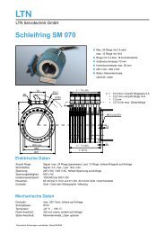
MODEL <strong>2790500</strong>RESOLVER TO ENCODER CONVERTERFOR MACHINE TOOL, POSITIONING, ANDTRANSFER LINE APPLICATIONS*** APPLICATIONS ***Ideal For Closed Loop Positioning SystemsMachine ToolsCoordinate Measuring MachinesPLC Positioning ControlIndex/Rotary TablesTracking/Telescope/Telemetry SystemsTransfer LinesPositioning SystemsRobotic ApplicationsDispensing SystemsRESOLVER TO DIGITAL INTERFACEWorks <strong>with</strong> Harowe/Danaher, Tamagawa, Kerfott,Singer, AMCI or most any Synchro/ResolverIncremental <strong>encoder</strong> <strong>output</strong> signalsMakes resolvers as easy to use as an <strong>encoder</strong>Jumper Selectable counts 1000, 1024, 2000, 2048,4000, 4096, 8000, and 8192 A-quad-B <strong>with</strong> Indexand complementsVEGAJumper2779501Selectablefor InductosynExcitationScale ApplicationsFrequencyincluding 2.5, 5.0, and 10 kHzWith the VEGA <strong>2790500</strong> <strong>converter</strong> you can have boththe ruggedness of an resolver and the digital simplicity ofan <strong>encoder</strong> interface. The <strong>2790500</strong> can be used <strong>with</strong>almost any resolver. The INDEX/MARKER pulse(Channel Z) will occur once per transducer cycle at thezero degree position.Excitation:<strong>2790500</strong>2.5,SPECIFICATIONS5, or 10 kHzExcitation:2.5, 5, or 10 kHzResolver Input: 0.8 to 18 vppPower Requirements: 5 vDC @ 250 mADrive Capacity: 200 mA PeakMechanical: 5.250 x 2.825 x 1.0005.400 x 3.500 x 1.850 w/DINAccuracy:+/- 3 arc minutes typicalCONVERTER ACCURACY AND TRACKING RATEThe tracking rate is a function of the excitation frequencyand quadrature counts. With a 2.5 kHz excitation and 4000quadrature counts the tracking rate would be 9,600 rpm.With a 10.0 kHz excitation and 4000 quadrature counts thetracking rate would be 38,400 rpm. Reducing the counts willincrease the tracking rate proportionately.*** ADVANCED FEATURES ***Incremental Encoder Output (*Absolute <strong>with</strong>in 1Resolver cycle)Non-Phase Locked Loop Design for Faster LoopClosure (Less than 50 uSec @ 10 kHz)High Resolution and Highly AccurateTuned Filter for Noise ImmunityA-Quad-B, Index and ComplementsTTL/Line Driver OutputsQuadrature <strong>encoder</strong> signals to 4 mHzSingle +5 vDC Supply OperationLoss of Phase DetectionFault Signal Output (Line Driver, and Active Pull-Up)Status LED’s for Power, A, B, Z, Signal HI, SignalMID, and FaultConfigurable Fault signal conditioning for Fail-Safe operations Compact Design and Easy to Install* Tracking limited to +/- 0.25 Resolver cycle <strong>with</strong> power offPRICING AND DELIVERYModel Description Price Delivery<strong>2790500</strong> Resolver to Digital $475.00 In Stock2790DIN DIN Rail Kit $ 24.00 In Stock2790CK1 Solder Connector Kit $ 17.00 In Stock2790CK2 Crimp Connector Kit $ 27.00 In Stock<strong>2790500</strong>_Rev. EVEGA CNC 1270 Souter Boulevard Troy, MI 48083 USA (248) 585-3600
VEGA <strong>2790500</strong> RESOLVER TO ENCODER SPECIFICATIONS AND CONNECTIONSP1 RESOLVER CONNECTORPIN# FUNCTION COLOR1 Sine HI Red2 Sine LO Black3 Sine Shield SHLD4 Cosine HI Yellow5 Cosine LO Blue6 Cosine Shield SHLD7 Feedback HI Red/Wht8 Feedback LO Yel/Wht9 Feedback Shield SHLD10 +5 vDC (*External) N/AP2 POWER CONNECTORPIN# FUNCTION COLOR*1 +5 vDC (*Same as P1-10) Red*2 DC Ground (*Same as P1-1) BlackQUADRATURE OUTPUTThe VEGA 2790 series of <strong>converter</strong> boards use RS-422-Adifferential drivers to provide 40 mA into a 100 ohmdifferential load. These <strong>output</strong>s are also TTL compatible.The <strong>output</strong> latency is dependent on the excitation frequency.At 2.5 kHz the response will be less than 200 uSec and at10.0 kHz the response will be less than 50 uSec.Quadrature is provided via Channel A+, Channel A-,Channel B+ and Channel B-. A count is considered to occurwhenever there is a transition in either the Channel A orChannel B <strong>output</strong> signals. The Channel Z (Index) occurs onceper resolver cycle. The phase relationship of the two signalsindicates the direction of motion as shown in the figure below.CHAN A+QUADRATURE OUTPUT FORMATCOUNTING UPCHAN A+COUNTING DOWNP3 ENCODER CONNECTORCHAN A-CHAN A-PIN# FUNCTION COLOR1 DC Ground (*Same as P2-2) Black2 Channel A+ Grey3 Channel B+ Yellow4 Channel Z+ Blue5 Reserved N/A6 Reserved N/A7 Reserved N/A8 Fault (TTL) Blu/Red9 Reserved N/A10 +5 vDC (*Same as P2-1) Red11 Reserved N/A12 Reserved N/A13 Reserved N/A14 Channel A- Violet15 Channel B- Orange16 Channel Z- Green17 Reserved N/A18 Reserved N/A19 !Fault (Active Pull-Up) Red/Blk20 !Fault (TTL) Blu/Blk21 Reserved N/A22 Reserved N/A23 Reserved N/A24 Reserved N/A25 Active Pull-Up vDC Blu/WhtCHAN B+CHAN B-CHAN Z+CHAN Z-0 1 2 3 4CHAN B+CHAN B-CHAN Z+CHAN Z-0 1 2 3 4VEGA CNC 1270 Souter Boulevard Troy, MI 48083 USA (248) 585-3600
JUMPER SETTINGSFREQUENCY SELECTION (B1-B2)The 2790 series of <strong>converter</strong>s provide selectable excitationfrequencies via SWB1 jumpers B1 and B2. Most resolverapplications are tuned to 2.5 kHZ.The 2790 also provides jumper selection of the active filternetwork for the return signal to provide the maximum noiseimmunity at the selected frequency. For the typical resolverapplication operating at 2.5 kHZ both J10 and J11 jumpersshould be installed. For excitation frequencies above 2.5 kHZboth jumpers should be removed. For low level signalcondition at 2.5 kHZ J10 can be removed to achieve a x4internal gain.DECIMAL/BINARY SELECTION (B3)The 2790 <strong>converter</strong> card provides both decimal and binarycounting modes. Installing SWB1 jumper B3 selects binarycounting mode to provide selection between 256, 512, 1024,and 2048 line counts. Removing jumper B3 selects thedecimal counting mode to provide selection between 250,500, 1000, and 2000 line counts.LINE COUNT SELECTION (B4-B5)The 2790 <strong>converter</strong> board provides 8 jumper selectable linecounts. Binary counts are selected by installing SWB1jumper B3 and installing the appropriate combination ofjumpers B4 and B5. Most systems using <strong>encoder</strong> stylefeedback are set to the x4 quadrature counting mode so thatthe effective quadrature counts are 4 times greater than thephysical line count of the <strong>encoder</strong>.RESERVED (B6-B9)On the 2790 <strong>converter</strong> board Jumpers B6-B9 are reservedand should have all jumpers removedSee Figure 1.0 for SWB1 Jumper Chart.CHANNEL Z NORMAL/INVERTED SELECTION (J2)The 2790 <strong>converter</strong> board provides jumper selectableinversion of the Z Channel (Index) for systems requiring anactive low signal. Jumper J2 pins 2-3 select the channel ZNormal mode and pins 1-2 select the Channel Z Invertedmode.FAULT MODE OUTPUT SELECTIONThe 2790 <strong>converter</strong> board provides several methods ofinterface for fail safe fault detection.DIFFERENTIAL FAULT SIGNAL SET-UP (J4)Installing a jumper on J4 pins 1-2 enables the RS-422-Adifferential drivers and provide up to 40 mA into a 100 ohmdifferential load. These <strong>output</strong>s are also TTL compatible andare located on pins 8 and 20 of the P3 connector.FAULTFAULTSHLDTRI-STATE A-QUAD-B FAULT SIGNAL SET-UP (J4)Install a jumper on J4 pins 2-3. The 2790 board will Tri-State the A-Quad-B signals as well as the Z Channel duringa Fault condition. The +/- Fault TTL signals located on P3pins 8 and 20 are also Tri-Stated and are NOT a validinterface <strong>with</strong> this set-up. This interface will allow animmediate Fault sense by equipment <strong>with</strong> loss of signaldetection.ACTIVE PULL-UP FAULT SIGNAL SET-UPThe active pull-up interface is a fail-safe design so that in aloss of power condition the 2790 will still drop the fault signalon Pin 19 of the P3 connector. Pin 19 will be the sourcevoltage <strong>with</strong> no fault present and can drive up to 600 mA.The source voltage for the Pull-up must be provided on Pin25 of the P3 connector and can range from 5-40 vDC.+5 to +40 VDCGNDCRFAULTACTIVE PULL-UP INTERFACE820TTL OR LINE DRIVER INTERFACE2519F1F1 - 1 AMPFUNCTION B1 B2 B3 B4 B5 B6 B7 B8 B9 Quadrature Counts2.5 kHZ 0 05.0 kHZ 1 010.0 kHZ 0 1Reserved 1 1Decimal Count 0Binary Count 1250/256 Lines 0 0 1000 Decimal/1024 Binary500/512 Lines 1 0 2000 Decimal/4048 Binary1000/1024 Lines 0 1 4000 Decimal/4096 Binary2000/2048 Lines 1 1 8000 Decimal/8192 BinaryDefault 0 0 0 0Reserved 1Reserved 1Reserved 1Reserved 1- Figure 1.0 -1 Indicates installed jumper Indicates default settingVEGA CNC 1270 Souter Boulevard Troy, MI 48083 USA (248) 585-3600
RESOLVER SET-UP PROCEDURE1) Install the 2790 board as described in the applicationdrawing <strong>2790500</strong>2) Select the fault signal conditioning method by settingthe J4 jumper as described in the JUMPERSETTINGS section and the jumper table (Fig. 1.0)based on the application requirements.3) Select the Z Channel inverted option by setting J2 toshort pins 1 and 2. The DEFAULT is non-invertingand having pins 2 and 3 shorted on J2.4) Select the excitation frequency by JB1-2 of SWB1(see jumper table Fig. 1.0). 2.5 kHZ is the DEFAULTsetting <strong>with</strong> both jumpers removed.5) Select the passive filter setting by J11 for thecorresponding frequency setting. The DEFAULTsetting is for a board set to 2.5 kHZ and J11 isinstalled.6) Select the counting style of Binary or Decimal by JB3of SWB1 (see jumper table Fig. 1.0). Decimal is theDEFAULT setting <strong>with</strong> the jumper removed.7) Select the line count per revolution by setting JB4-5of SWB1 (see jumper table Fig. 1.0). 1000 lines perrevolution (4000 quadrature counts per revolution) isthe DEFAULT setting <strong>with</strong> JB4 removed and JB5installed.9) J10 selects in the input course gain range and allowsfor interface to a broad range of resolver transformationratios. Installing a jumper on pins 1 and 2 sets the gainto 0.25 (gain of ¼). Installing a jumper on pins 2 and 3sets the gain to 1.0 and removing the jumperscompletely sets the gain to 4.0.10) Turn the gain potentiometer fully counter-clockwise.Then turn the gain potentiometer clock-wise until theMID LED comes on. The signal return on “ST1” testpoint should now be 3.8 volts peak to peak. Phase theposition loop if necessary by reversing the Sine HI andSine LO wires to reverse the count direction. At thispoint the basic set-up is complete and the position loopcan now be closed. Set the position loop gain of theservo system and then continue to Step 11.11) After the position loop has been closed the phasebalance of the 2790 board can be adjusted. To adjustthe phase balance of the 2790 board, observe theexcitation return on the “ST1” test point. Adjust theoscilloscope to 100 mvDC per division and offset thesignal so that just the peak of the signal is visible. Jogthe axis at 30% of its feedrate. If the phase isunbalanced the peak of the sine wave will bounce andbecome blurred. Adjust the balance pot (BAL) on the2790 to achieve 20 mvDC or less bounce.8) Jumpers JB6-8 are reserved on the <strong>2790500</strong> andshould be removed.LED STATUS INDICATORSCHA = Channel A State IndicatorCHB = Channel B State IndicatorCHZ = Channel Z (Index/Marker) IndicatorPWR = Power Status IndicatorFLT = Loss of Signal IndicatorMID = Return Signal Proper IndicatorHSG = High Signal IndicatorTEST POINTSGND = Analog GroundPA+ = Sine HI (3.6 vDC Peak to Peak)PA- = Sine LO (3.6 vDC Peak to Peak)PB+ = Cosine HI (3.6 vDC Peak to Peak)PB- = Cosine LO (3.6 vDC Peak to Peak)SIG = Signal Return (0.8-18.0 vDC Peak to Peak)ST1 = Stage 1 Signal (3.8 vDC Peak to Peak)SCL = Tracking ClockVEGA CNC 1270 Souter Boulevard Troy, MI 48083 USA (248) 585-3600
TROUBLE SHOOTINGSYMPTOM CHECKS SOLUTIONNo Power LED Check +5 vDC +5 vDC Present Board Failure – ReplaceboardFault LED (Low Signal)ContinuousRemove power and ohm between “PA+“and “PA-“ note value. Ohm between “PB+”and “PB-“ note value.If resistance values are less than 30.0 ohms –Check for shorts between “PA-“ and “PA+” aswell as ground. Check for shorts between “PB-“and “PB+” as well as ground.Check “PA+” and “PB+“test point for 3.6volts peak to peak sine excitationSignal not present Board Failure – ReplaceboardFault LED (Low Signal)IntermittentCyclic ErrorHSG LED (High Signal)ContinuousHSG LED (High Signal)IntermittentMID LED (Signal Midpoint)ContinuousMID LED (Signal Midpoint)IntermittentFeedback Polarity isReversedCheck “PA-” and “PB-“test point for 3.6volts peak to peak sine excitationCheck “ST1” test point for 3.8 volts peak topeakCheck “PA+” and “PB+“test point for 3.6volts peak to peak sine excitationCheck “PA-” and “PB-“test point for 3.6volts peak to peak sine excitationRemove power and ohm between “PA+“and “PA-“ note value. Ohm between “PB+”and “PB-“ not value.Remove power and ohm between “PA+“and “PA-“ note value. Ohm between “PB+”and “PB-“ note value.Check “ST1” test point for bounceCheck “ST1” test point for bounceRemove power and ohm between “PA+“and “PA-“ note value. Ohm between “PB+”and “PB-“ note value.Remove power and ohm between “PA+“and “PA-“ note value. Ohm between “PB+”and “PB-“ note value.Check “PA+” and “PA-“test point for 3.6volts peak to peak sine excitationCheck “PB+” and “PB-“test point for 3.6volts peak to peak sine excitationCheck “ST1” test point for 3.8 volts peak topeakCheck “ST1” test point for 3.8 volts peak topeakSignal ProperCheck “ST1” test point for bounceNoneSignal not present Board Failure – ReplaceboardRepeat Step 9-10 of the Resolver Set-UpProcedureSignal not present Board Failure – ReplaceboardSignal not present Board Failure – ReplaceboardIf resistance values differ by more than 3 ohmsof each other Check Resolver connections –Replace resolver or cablesIf resistance values are less than 30.0 ohms –Check for shorts between “PA-“ and “PA+” aswell as ground. Check for shorts between “PB-“and “PB+” as well as ground.Repeat step 11 of the Resolver Set-UpProcedureRepeat step 11 of the Resolver Set-UpProcedureIf resistance values are less than 30.0 ohms –Check for shorts between “PA-“ and “PA+” aswell as ground. Check for shorts between “PB-“and “PB+” as well as ground.If resistance values are differ by more than 3ohms of each other Check Resolverconnections – Replace resolver or cablesSignal not present Board Failure – ReplaceboardSignal not present Board Failure – ReplaceboardRepeat Step 9-10 of the Resolver Set-UpProcedureFollow procedures described in the Fault LED(Low Signal) Intermittent sectionNo Problem… Life is GoodRepeat step 11 of the Resolver Set-UpProcedureSwapping the Sine HI <strong>with</strong> the Sine LO wireswill reverse the counting direction of the A-quad-BVEGA CNC 1270 Souter Boulevard Troy, MI 48083 USA (248) 585-3600
ELECTRICALPOWER REQUIREMENTSThe <strong>2790500</strong> <strong>converter</strong> requires +5 vDC supply @ 250 mAmpfor operation. The supplied power should have less than 50mVolts of noise and drift.Recommended Power Supplys (If Required)Mean Well MDR-20-5 (+5 vDC @ 3 Amps)Mean Well MDR-40-5 (+5 vDC @ 6 Amps)CABLE SPECIFICATIONSThe 2790 series of <strong>converter</strong>s provide stable and precise sineand cosine excitations. These signals and the return signal areanalog and proper routing and shielding techniques should beobserved. Shielded twisted pair cables should be used for allinterface signals.Recommended CableShielded Twisted Pair <strong>with</strong> Drain WireBelden #8103 or equivalentACCESSORIES and SUPPORTConnector Kits and Mounting OptionsKIT #2790CK1Includes:(1) DB-25 Male Solder Cup Connector(1) DB-25 Plastic Hood and HardwareKIT #2790CK2Includes:(1) DB-25 Male Crimp Style Connector(25) Gold Male Crimp Pins(1) DB-25 Plastic Hood and Hardware* Use Molex Crimper HTR2445A orgeneral purpose crimper HT202A (Jameco PN 99443)KIT #2790DINIncludes:(1) DIN Rail Mount for 2790 boardsREPAIR AND TECHNICAL SUPPORTMonday-Friday 8:00am to 6:00pm EasternVEGA CNC 1270 Souter Boulevard Troy, MI 48083 USA (248) 585-3600