Sensorless fault diagnosis of induction motors - Networked ...
Sensorless fault diagnosis of induction motors - Networked ...
Sensorless fault diagnosis of induction motors - Networked ...

Create successful ePaper yourself
Turn your PDF publications into a flip-book with our unique Google optimized e-Paper software.
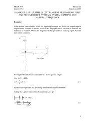
KIM et al.: SENSORLESS FAULT DIAGNOSIS OF INDUCTION MOTORS 1047Fig. 7. Impact <strong>of</strong> speed estimation for 2.2-kW motor with broken rotor bars; current residual generated by measured speed and estimated speed (top),Indicator 1 (middle), and Indicator 2 (bottom).is used to load the <strong>induction</strong> motor. The second dc generator isused to measure the motor speed signal. An eight-channel Lab-VIEW-based data acquisition system is used to record the threeline voltages, the three line currents, and the generator speedsignal. All seven signals are sampled at 3840 Hz and the dataare collected for <strong>of</strong>fline processing.Data from electric motor experiments conducted at thePublic Service Electric and Gas Motor Repair Facility, Sewaren,NJ, under the auspices <strong>of</strong> the Electric Power ResearchInstitute (EPRI) and the Electric Motor Predictive Maintenance(EMPM) Tailored Collaboration (TC) project are used. This isthe large machine test bed. A six-pole 373-kW and aeight-pole 597-kW <strong>induction</strong> motor are run directly from thepower supply mains. The <strong>motors</strong> are connected to dynamometersused to load then. A 13-channel IOTech data-acquisitionsystem is used to record the three line voltages, the three linecurrents, the encoder speed signal and six vibration signals.The currents, voltages and the encoder signal downsampled to3840 Hz are utilized for further processing.B. Impact <strong>of</strong> Speed Estimation on Fault Detection AccuracyThe developed motor predictors have the mechanical speedas an input. At the motor predictor training stage, the measuredspeed information is used as the speed input to these predictors.But speed measurements are not always available becausespeed sensors are not typically installed in <strong>induction</strong> <strong>motors</strong>,especially in small ones. Due to recent developments insensorless speed estimation schemes, accurate state filtering <strong>of</strong>the motor speed using only the electrical measurements is feasible,as discussed in previous sections. To demonstrate the effectiveness<strong>of</strong> the developed <strong>fault</strong> <strong>diagnosis</strong> system when speedestimates are used rather than speed measurements, both thespeed measurements and the speed filter output are utilized forresidual generation. Figs. 6 and 7 show this comparison for ahealthy motor and a motor having broken rotor bars, respectively.The measured speed is used for computing the <strong>fault</strong> indicatorsduring the first 2 s <strong>of</strong> the case studies, whereas theestimated speed is used during the next 2 s. All other measurementsare identical. In both figures, the magnitude <strong>of</strong> theresidual signal is indistinguishable throughout the tests, as is theindicator values. These figures demonstrate the accuracy <strong>of</strong> thedeveloped speed estimates and the robustness <strong>of</strong> the <strong>fault</strong> indicators.Consequently, most <strong>of</strong> the <strong>fault</strong> detection and <strong>diagnosis</strong> resultspreviously reported by the authors using speed sensor measurements[19], [20] are quite similar to the results presented inthis paper.