Sensorless fault diagnosis of induction motors - Networked ...
Sensorless fault diagnosis of induction motors - Networked ...
Sensorless fault diagnosis of induction motors - Networked ...

You also want an ePaper? Increase the reach of your titles
YUMPU automatically turns print PDFs into web optimized ePapers that Google loves.
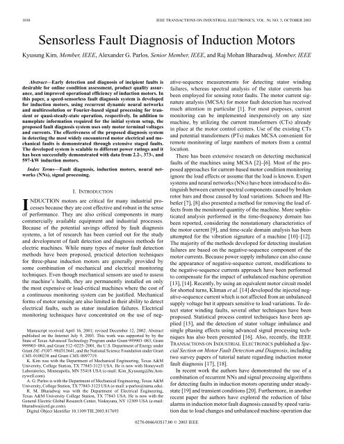
1038 IEEE TRANSACTIONS ON INDUSTRIAL ELECTRONICS, VOL. 50, NO. 5, OCTOBER 2003<strong>Sensorless</strong> Fault Diagnosis <strong>of</strong> Induction MotorsKyusung Kim, Member, IEEE, Alexander G. Parlos, Senior Member, IEEE, and Raj Mohan Bharadwaj, Member, IEEEAbstract—Early detection and <strong>diagnosis</strong> <strong>of</strong> incipient <strong>fault</strong>s isdesirable for online condition assessment, product quality assurance,and improved operational efficiency <strong>of</strong> <strong>induction</strong> <strong>motors</strong>. Inthis paper, a speed-sensorless <strong>fault</strong> <strong>diagnosis</strong> system is developedfor <strong>induction</strong> <strong>motors</strong>, using recurrent dynamic neural networksand multiresolution or Fourier-based signal processing for transientor quasi-steady-state operation, respectively. In addition tonameplate information required for the initial system setup, theproposed <strong>fault</strong> <strong>diagnosis</strong> system uses only motor terminal voltagesand currents. The effectiveness <strong>of</strong> the proposed <strong>diagnosis</strong> systemin detecting the most widely encountered motor electrical and mechanical<strong>fault</strong>s is demonstrated through extensive staged <strong>fault</strong>s.The developed system is scalable to different power ratings and ithas been successfully demonstrated with data from 2.2-, 373-, and597-kW <strong>induction</strong> <strong>motors</strong>.Index Terms—Fault <strong>diagnosis</strong>, <strong>induction</strong> <strong>motors</strong>, neural networks(NNs), signal processing.I. INTRODUCTIONINDUCTION <strong>motors</strong> are critical for many industrial processesbecause they are cost effective and robust in the sense<strong>of</strong> performance. They are also critical components in manycommercially available equipment and industrial processes.Because <strong>of</strong> the potential savings <strong>of</strong>fered by <strong>fault</strong> <strong>diagnosis</strong>systems, a lot <strong>of</strong> research has been carried out for the studyand development <strong>of</strong> <strong>fault</strong> detection and <strong>diagnosis</strong> methods forelectric machines. While many types <strong>of</strong> motor <strong>fault</strong> detectionmethods have been proposed, practical detection techniquesfor three-phase <strong>induction</strong> <strong>motors</strong> are generally provided bysome combination <strong>of</strong> mechanical and electrical monitoringtechniques. Even though mechanical sensors are used to assessthe machine’s health, they are permanently installed on onlythe most expensive or load-critical machines where the cost <strong>of</strong>a continuous monitoring system can be justified. Mechanicalforms <strong>of</strong> motor sensing are also limited in their ability to detectelectrical <strong>fault</strong>s, such as stator insulation failures. Electricalmonitoring techniques have concentrated on the use <strong>of</strong> neg-Manuscript received April 16, 2001; revised December 12, 2002. Abstractpublished on the Internet July 9, 2003. This work was supported by by theState <strong>of</strong> Texas Advanced Technology Program under Grant 999903–083, Grant999903–084, and Grant 512–0225–2001, the U.S. Department <strong>of</strong> Energy underGrant DE–FG07–98ID13641, and the National Science Foundation under GrantCMS–0100238 and Grant CMS–0097719.K. Kim was with the Department <strong>of</strong> Mechanical Engineering, Texas A&MUniversity, College Station, TX 77843-3123 USA. He is now with HoneywellLaboratories, Minneapolis, MN 55418 USA (e-mail: Kim_Kyusung@htc.honeywell.com).A. G. Parlos is with the Department <strong>of</strong> Mechanical Engineering, Texas A&MUniversity, College Station, TX 77843-3123 USA (e-mail: a-parlos@tamu.edu).R. M. Bharadwaj was with the Department <strong>of</strong> Electrical Engineering,Texas A&M University College Station, TX 77843 USA. He is now with theGeneral Electric Global Research Center, Niskayuna, NY 12309 USA (e-mail:bharadwa@crd.ge.com).Digital Object Identifier 10.1109/TIE.2003.817693ative-sequence measurements for detecting stator windingfailures, whereas spectral analysis <strong>of</strong> the stator currents hasbeen employed for sensing rotor <strong>fault</strong>s. The motor current signatureanalysis (MCSA) for motor <strong>fault</strong> detection has receivedmuch attention in particular [1]. For most purposes, currentmonitoring can be implemented inexpensively on any sizemachine, by utilizing the current transformers (CTs) alreadyin place at the motor control centers. Use <strong>of</strong> the existing CTsand potential transformers (PTs) makes MCSA convenient forremote monitoring <strong>of</strong> large numbers <strong>of</strong> <strong>motors</strong> from a centrallocation.There has been extensive research on detecting mechanical<strong>fault</strong>s <strong>of</strong> the machines using MCSA [2]–[6]. Most <strong>of</strong> the proposedapproaches for current-based motor condition monitoringignore the load effects or assume that the load is known. Expertsystems and neural networks (NNs) have been introduced to distinguishbetween current spectral components caused by brokenrotor bars and those caused by load variations. Schoen and Habetler[7], [8] also presented a method for removing the load effectsfrom the monitored quantity <strong>of</strong> the machine. More sophisticatedanalysis performed in the time-frequency domain hasbeen reported, considering the nonstationary characteristics <strong>of</strong>the motor current [9], and time-scale domain analysis has beenattempted for the vibration signature <strong>of</strong> a machine [10]–[12].The majority <strong>of</strong> the methods developed for detecting insulationfailures are based on the negative-sequence component <strong>of</strong> themotor currents. Because power supply imbalance can also causethe appearance <strong>of</strong> negative-sequence current, modifications tothe negative-sequence currents approach have been performedto compensate for the impact <strong>of</strong> unbalanced machine operation[13], [14]. Recently, by using an equivalent motor circuit modelfor shorted turns, Kliman et al. [14] developed the injected negative-sequencecurrent which is not affected from an unbalancedsupply voltage but it appears sensitive to load variations. To detectstator winding <strong>fault</strong>s, several other techniques have beenproposed. Statistical process control techniques have been applied[15], and the detection <strong>of</strong> stator voltage imbalance andsingle phasing effects using advanced signal processing techniqueshas also been presented [16]. Also, recently, the IEEETRANSACTIONS ON INDUSTRIAL ELECTRONICS published a SpecialSection on Motor Fault Detection and Diagnosis, includingtwo survey papers <strong>of</strong> tutorial nature regarding <strong>induction</strong> motor<strong>fault</strong> <strong>diagnosis</strong> [17], [18].In recent work the authors have demonstrated the use <strong>of</strong> acombination <strong>of</strong> recurrent NNs and signal processing algorithmsfor detecting <strong>fault</strong>s in <strong>induction</strong> <strong>motors</strong> operating under steadystate[19] and transient conditions [20]. Furthermore, in anotherrecent paper the authors have explored the reduction <strong>of</strong> falsealarms in <strong>induction</strong> motor <strong>fault</strong> <strong>diagnosis</strong> caused by speed variationdue to load changes and unbalanced machine operation due0278-0046/03$17.00 © 2003 IEEE
KIM et al.: SENSORLESS FAULT DIAGNOSIS OF INDUCTION MOTORS 1039to supply imbalance [21]. In all these three recent studies, in additionto electrical motor sensors the availability <strong>of</strong> a mechanicalspeed sensor is assumed available. In the current paper, standardFourier-based and wavelet-based signal processing techniquesare used with identified, empirical motor models to estimate<strong>fault</strong> features for the detection and <strong>diagnosis</strong> <strong>of</strong> electricaland mechanical motor <strong>fault</strong>s. The availability <strong>of</strong> motor electricalmeasurements is assumed, as is motor nameplate information.However, no speed or other mechanical sensor is assumed available.Motor speed is estimated from the electrical terminal measurementsusing a state filter based on an empirical motor model[22], [23]. The scalability <strong>of</strong> the developed sensorless <strong>fault</strong> <strong>diagnosis</strong>system is demonstrated with experimental results on smalland large <strong>induction</strong> <strong>motors</strong>. The main contributions <strong>of</strong> this paperare the:• development and demonstration <strong>of</strong> a sensorless motor<strong>fault</strong> detection and <strong>diagnosis</strong> system based on an empiricalpredictor and on other signal processing algorithms,that is effective in detecting the most widely encounteredelectrical and mechanical <strong>fault</strong>s;• demonstration <strong>of</strong> the <strong>fault</strong> detection and <strong>diagnosis</strong> systemscalability to <strong>induction</strong> <strong>motors</strong> <strong>of</strong> different power ratings.The remainder <strong>of</strong> this paper is organized as follows. In SectionII, the proposed <strong>fault</strong> <strong>diagnosis</strong> system with its two separateoperating modes is briefly described. Section III presentsa brief description <strong>of</strong> a recently developed motor speed filterbased on recurrent dynamic NNs. Section IV presents the proceduresused in developing the motor predictor for residual generation,its scalability to <strong>motors</strong> <strong>of</strong> higher rating and the signalprocessing methods used in computing the proposed <strong>fault</strong> indicators.Section V presents the experimental results obtainedfrom the <strong>fault</strong>s staged on small and large <strong>induction</strong> <strong>motors</strong>, includingstudies on the impact <strong>of</strong> speed estimation error on <strong>fault</strong>detection accuracy. Finally, in Section VI the conclusions drawnfrom this study are presented.II. PROPOSED FAULT DIAGNOSIS SYSTEMA <strong>fault</strong> <strong>diagnosis</strong> system is said to perform accurately if exhibitshigh <strong>fault</strong> detection rates and low false alarm rates, whilemaximizing the correct classification <strong>of</strong> detected <strong>fault</strong>s. If thedetection capability <strong>of</strong> a <strong>fault</strong> <strong>diagnosis</strong> system is poor, thenit is likely to miss developing <strong>fault</strong>s. Missed <strong>fault</strong>s may leadto critical machine failures and breakdowns <strong>of</strong> entire systems.Whereas, if the <strong>fault</strong> detection system is too sensitive then it islikely to generate high rates <strong>of</strong> false alarms. Every alarm forcesthe operator decide whether or not to shut down the system. Frequentfalse alarms may lead the operator to question the effectiveness<strong>of</strong> a <strong>fault</strong> <strong>diagnosis</strong> system, increasing the potential <strong>of</strong>ignored alarms that indicate a real system <strong>fault</strong>. So any practical<strong>fault</strong> <strong>diagnosis</strong> system must have low rates <strong>of</strong> missed <strong>fault</strong>s andfalse alarms, while maximizing the correct detection and classification<strong>of</strong> actual unhealthy and healthy conditions.In general, motor currents and voltages are nonstationarysignals, because their temporal properties are influenced bymany factors during motor operation, including electric powersupply and load variations. If the motor load torque variesover time, then the stator current spectrum contains loadFig. 1.Proposed model-based <strong>fault</strong> detection and <strong>diagnosis</strong> system.induced harmonics that might obscure certain spectral <strong>fault</strong>signatures. This situation complicates any proposed motor <strong>fault</strong>detection scheme that depends solely on stator current. A <strong>fault</strong><strong>diagnosis</strong> system that utilizes nonstationary signals must takeinto account the temporal variations <strong>of</strong> the <strong>fault</strong> signatures,requiring more sophisticated signal processing techniquesthan one that utilizes stationary signals. The proposed <strong>fault</strong><strong>diagnosis</strong> system consists <strong>of</strong> two operating modes; one thatis applicable for <strong>motors</strong> operating for prolonged periods inquasi-steady state, where finding stationary segments <strong>of</strong> motorterminal measurements is feasible, and a second applicable for<strong>motors</strong> operating predominantly in transient mode.The block diagram <strong>of</strong> the proposed <strong>fault</strong> <strong>diagnosis</strong> systemfor both operating modes is shown in Fig. 1. Measurements <strong>of</strong>three-phase line voltages, , and currents, , are collected,where stands for “nonstationary.” The samples arepreprocessed to match with the sampling rate and magnitudescale <strong>of</strong> the developed motor predictor. Then using these motorterminal measurements the motor speed, , is estimatedusing the speed filter. In the case <strong>of</strong> the steady-state algorithm,it is necessary to obtain the stationary segments <strong>of</strong> the measuredsignals. By applying a segmentation technique to the measurementsand the speed estimate, the desired stationary regions are
1040 IEEE TRANSACTIONS ON INDUSTRIAL ELECTRONICS, VOL. 50, NO. 5, OCTOBER 2003Fig. 2.Stator current FFT representation for a 2.2-kW motor operating at 60 Hz (2.5-Hz slip).extracted. The motor condition is analyzed in these regions bygenerating the residual signals. The empirical motor predictorsused in generating the residual signals are multi-step-ahead predictors(MSP) based on recurrent dynamic NNs, and their inputsare the voltage measurements, , current predictions,, and motor speed estimate, , where standsfor “quasi-stationary.” Once the residuals are generated,they are further processed along with the current measurement. These signals are separated to their fundamental andharmonics components, , , and , .Since the magnitude <strong>of</strong> and does not changeover the time, the fast Fourier transform (FFT) algorithm canbe used to separate it into fundamental and harmonics components.These signals are used to generate two different <strong>fault</strong> indicators,, which is the rms value <strong>of</strong> the normalized harmonicscomponent <strong>of</strong> the residual signal, and , whichis the negative-sequence component <strong>of</strong> the residual signal. Theformer indicator is developed for detecting mechanical <strong>fault</strong>s,whereas the latter for detecting electrical <strong>fault</strong>s. By detectingchanges in the indicator magnitude, the motor condition is classifiedas normal, warning, or alarm.In the transient mode <strong>of</strong> operation, the sampled nonstationarysignals are preprocessed and the motor current residual signalsare generated, which are also nonstationary. The current measurementsand the residuals are then separatedinto fundamental and harmonics components , ,and , . Wavelet signal decomposition is used in thisresearch to track the temporal variations <strong>of</strong> the relevant signals.The <strong>fault</strong> indicators used in this mode are modified to reflectthe time variations. Once the time-dependent frequency components<strong>of</strong> and are separated, the <strong>fault</strong> indicatorsand are computed through the rms and symmetricalcomponent analysis calculations, respectively.III. SENSORLESS SPEED ESTIMATIONA. Speed Estimation From Motor Current Rotor Slot HarmonicThe rotor produces air-gap permeance waves with a spatialdistribution dependent upon the number <strong>of</strong> rotor slots, .During motor operation, the rotor-slot magnetomotive force(mmf) harmonics interact with the fundamental component <strong>of</strong>the air-gap flux due to the stator current. Normally, the magnitude<strong>of</strong> these flux harmonics varies little, except in machineswith closed rotor slots. Similar air-gap flux harmonics occurfrom the rotor slot harmonics (RSHs). Therefore the air-gapflux is modulated by the passing rotor slots.For a sinusoidally fed machine the expression for slot harmoniccan be given as [1],where , , and are angular slot harmonic frequency,rotor frequency, and synchronous frequency, respectively. Accountingfor the time harmonics present in the power supplyand air-gap eccentricity, the equation for the slot harmonic frequencycan be given as [1]where ; , is known as eccentricityorder,is the order <strong>of</strong> stator time harmonicsthat are present in the power supply. Due to the interaction<strong>of</strong> harmonics with the rotor slot permeance wave,there is a periodicity <strong>of</strong> slot harmonics. Fig. 2 shows the slotharmonics corresponding to and for a2.2-kW four-pole 44–rotor-bars machine, running directly fromthe power supply mains.(1)(2)
KIM et al.: SENSORLESS FAULT DIAGNOSIS OF INDUCTION MOTORS 1041In order to use (2) to calculate the slip, it is necessary to knowand . In this study, only motor nameplate informationis used for finding the number <strong>of</strong> rotor bars along with motorcurrent measurements [24]. The lower eccentricity-related harmonicis not automatically detectable for the small <strong>induction</strong>motor ( , 2.2 kW) used in this study. Thus, the approximateslip in the initialization algorithm adopted from [24] wascalculated by using the no-load and full-load slip and the rmsvalue <strong>of</strong> the motor current. This assumes motor operation in thelinear region. Using the approximate slip, the number <strong>of</strong> rotorbars is calculated as the value <strong>of</strong> for which the magnitude<strong>of</strong> is maximum in the line current spectrum [24]. The <strong>induction</strong>motor speed, in revolutions per minute (r/min), canthen be calculated using the slot harmonic frequency at any slipcondition from the following expression [25]:The RSH-based speed detection algorithms require calculation<strong>of</strong> the motor stator current FFT. For accurate detection <strong>of</strong> theRSH, a high frequency resolution is required, typically 1–2 Hz,which in turn implies longer data windows. The transient speedcan thus be calculated by using a moving data window, but thisleads to poor time localization <strong>of</strong> the estimated transient speedresponse.An FFT-based algorithm with multiple time and frequencywindowing is used to search for the RSH. This approach is acombination <strong>of</strong> the time-windowing [25] and spectral aliasingmethods [24] discussed in the literature. The search window isgiven byis derived from nameplate infor-is the slip corresponding to no load.where the value <strong>of</strong>mation and the value <strong>of</strong>(3)(4)B. Neural Speed Filter DevelopmentIt is assumed that the motor voltage and current measurementsare available and these are used to identify a motor modelfor the speed filter. Motor nameplate information, such as ,orquantities derived from motor nameplate, such as ,and , is used to calculate the speed targets, , from themotor line currents. Only the motor terminal measurements andthe inferred target speed are required for filter development,whereas online filter operation requires only the motor terminalcurrents and voltages.The filter equations for the motor speed estimate,, can be written as [23]: follows.Step 1) Prior to Observing the Sample—PredictionStep: The motor speed and current predictor valuesare obtained using the following equations:(5)(6)where and where andrepresent the measured motor line voltages andcurrents, andis the vector containingthe history <strong>of</strong> motor current predictions.Step 2) Following Observation <strong>of</strong> the Sample—UpdateStep: The updated motor speed is computedfrom(7)where the function is the filter gain, a function<strong>of</strong> the variables shown in (7), and the vector,, is defined aswhereis the innovations term.A block diagram <strong>of</strong> the neural adaptive speed filter is shown inFig. 3. The motor speed estimaterepresentsthe speed estimate computed during the online operation <strong>of</strong> thefilter.A data buffer <strong>of</strong> 20 cycles, sampled at 3840 Hz with windowing,is used to find the RSH. Since 20 cycles <strong>of</strong> data areneeded to calculate the speed, the RSH speed estimate lags theactual speed by about 10 cycles. As such, the RHS-based speedestimate is shifted to compensate for this sluggishness or lag.The training set consists <strong>of</strong> the measurements <strong>of</strong> the three linevoltages, the three line currents, rms <strong>of</strong> the phase- current andthe shifted RSH-based speed estimate. The rms <strong>of</strong> the phasecurrentis calculated using only two-cycles <strong>of</strong> a moving window.Hence the current rms value calculation block can be embeddedinside the neural speed filter. All eight training set signals aredownsampled to 960 Hz. The training set contains <strong>of</strong> both transientsas well as steady-state segments.C. Neural Speed Filter Experimental ValidationThe speed filter is first developed to estimate the healthymotor speed under balanced power supply conditions, usingmotor voltages and currents from a healthy balanced machine.The load is varied from 70% to 120% <strong>of</strong> rated (high load). Thefilter is then tested on unseen data in the same load range. The response<strong>of</strong> the filter is also tested for load range 0%–70% <strong>of</strong> rated(low load), which is outside the loads in the range for whichthe filter was trained. Both studies reveal acceptable speed estimates.The filter response is also tested on data collected using arotor different that the one used in filter training. In any speedestimation technique based on a motor model, use <strong>of</strong> differentrotors would typically require <strong>of</strong>fline calculation <strong>of</strong> model parameters.This is not the case for the neural speed filter developed.Table I presents a summary <strong>of</strong> the speed estimation errors.The neural speed filter response has significant speed estimationerror when a new rotor is introduced and no online training or(8)(9)
1042 IEEE TRANSACTIONS ON INDUSTRIAL ELECTRONICS, VOL. 50, NO. 5, OCTOBER 2003Fig. 3.Block diagram <strong>of</strong> the motor speed filter.tuning is performed. However, this error is considerably reducedafter only two iterations <strong>of</strong> incremental tuning.The three-phase power supply in an industrial environment isnot always balanced. Due to the supply imbalance negative-sequencecurrents would be generated in the machine, leading toa drop in speed. The speed filter response is studied for supplyimbalance varying from 0% to 5.4%. The speed filter with parameterscorresponding to the “balanced healthy machine” isused to investigate the impact <strong>of</strong> power supply imbalance. Theneural filter response with no parameter tuning is found satisfactory.Fig. 4 shows the performance <strong>of</strong> speed filter with highvalues <strong>of</strong> supply imbalance. Table I presents a summary <strong>of</strong> thespeed filtering error with respect to shifted RSH-based speedestimate.The filter performance is also tested on a rotor with brokenbars, that is different than the one used in filter development. Acceptableresults are obtained for all the broken rotor bar cases.Moreover, no filter training or tuning is needed to obtain goodspeed estimates for the rotor with broken rotor bars. Table Ipresents a speed error comparison, with respect to the shiftedRSH-based speed estimates. The response <strong>of</strong> the filter deterioratesas the number <strong>of</strong> broken bars increases.The scalabilty and adaptability <strong>of</strong> the speed filter to a new machineis tested with the 597-kW motor. The speed filter developedfor the healthy 2.2-kW machine is used as a starting point.Incremental training with a very small transient segment is sufficientto considerably improve the performance <strong>of</strong> the filter inonly a few hundred iterations. Fig. 5 shows the speed filter responsefollowing this incremental tuning, whereas Table I summarizessome <strong>of</strong> the estimation error results for the two largemachines considered. The ability <strong>of</strong> the speed filter to be adaptableto new machines with little incremental tuning effort showsits reusability. Furthermore, it significantly reduces the commissioningtime needed to install the filter on a new machine.For the 597-kW machine, the speed filter performance is alsotested on data with four broken rotor bars. Moreover, no furtheronline training or tuning <strong>of</strong> the filter is needed to obtain goodspeed estimates. Similar results are obtained for this case studyduring load increase and decrease. Table I present the speed filteringerrors for healthy, broken bars and eccentric 597-kW machine.Since the measured speed encoder signal is very noisy,the errors are calculated with respect to the shifted RSH-basedspeed estimate.IV. DEVELOPMENT OF MOTOR PREDICTORS AND COMPUTATIONOF THE FAULT INDICATORSA. Generation <strong>of</strong> the Motor Current Residual SignalsThe current residuals are computed by taking the differencebetween the measured and predicted motor current responses.The latter is the output <strong>of</strong> the developed motor predictor. Themotor current predictor consists <strong>of</strong> three networks; a networkis developed for each <strong>of</strong> the outputs <strong>of</strong> the three-phase <strong>induction</strong>motor, , , and . Each network has three
KIM et al.: SENSORLESS FAULT DIAGNOSIS OF INDUCTION MOTORS 1043TABLE INEURAL SPEED ESTIMATION ERRORS FOR SMALL AND LARGE INDUCTION MOTORSconsists <strong>of</strong> the three-phase current predic-outputtions(10)The nine inputs to each <strong>of</strong> the three current predictors are(11)whererepresents the three-phase motor terminal voltages,(12)Fig. 4. Comparison <strong>of</strong> speed filter response for 2.2-kW healthy motor fed frompower supply with 4.5% imbalance; 0%–70% load range and no filter tuning.layers: one hidden layer, one input layer with nine nodes, andone output layer with one node. Specifically, the neural predictorand where , , and represent the three phase currents. Thearchitecture <strong>of</strong> the current predictor is similar to the speed filterpredictor, i.e., (5) and (6).Initially, the motor predictors are developed for a small machine,2.2 kW, with the training data representing the high-load
1044 IEEE TRANSACTIONS ON INDUSTRIAL ELECTRONICS, VOL. 50, NO. 5, OCTOBER 2003Fig. 5.Comparison <strong>of</strong> the speed filter response for 597-kW healthy motor following incremental tuning; 100%–50% load reduction.level, 90%–100%. After developing this baseline model, additionalmodels valid at lower load levels, e.g., 50%–60% <strong>of</strong>rated load, are developed by incrementally tuning the baselinehigh-load level model. This is done to allow compensation forload variation effects on the <strong>fault</strong> signatures. The motor loadlevel can be determined by the speed or current measurement,compared to the rated speed and current <strong>of</strong> the motor. The predictoralso allows for supply imbalance compensation; supplyimbalance <strong>of</strong> only up to 5.4% is considered because imbalance<strong>of</strong> much more than 5% is considered excessive. In this research,only magnitude imbalance is considered. Training <strong>of</strong> the predictoris accomplished using a recurrent learning algorithm previouslypresented in the literature. The details <strong>of</strong> the algorithm,including the gradient calculations are omitted here, but theyhave been published in the literature [26].In testing the performance <strong>of</strong> the developed predictor, themaximum and mean prediction error is used. Additionally, thefollowing normalized mean-squared error (NMSE) is utilizedfor the th predicted variable:(13)where is the observed output, and isthe predicted output. The developed predictors are evaluatedin terms <strong>of</strong> their performance for multi-step-ahead prediction(MSP) on a validation data set. The validation data set comprises<strong>of</strong> measurements entirely different than the ones used inthe estimation data set. The performance evaluation results forthe validation set are summarized in Table II in terms <strong>of</strong> NMSE,maximum error and mean error. The results reported in Table IIare comparable to the errors obtained using the estimation set,demonstrating the generalization performance <strong>of</strong> the predictors.In predictor adaptation for use with large <strong>motors</strong>, a 597 kWmachine and a 373-kW machine is considered. The originalpredictor is adapted for use with both <strong>of</strong> these machines. Theadapted predictors are further tuned incrementally to obtain newpredictors operating at lower load levels. The predictive accuracy<strong>of</strong> the adapted models is shown in Table II in terms <strong>of</strong>NMSE, maximum error and the mean error. Compared to theaccuracy <strong>of</strong> the original predictors, the predictors adapted forthe large machines show improvement. The large machine dataare collected using better sensors and with very high samplingrates, reducing the effects <strong>of</strong> aliasing and noise. Further, in largemachines the signal-to-noise ratio (SNR) is much higher than insmall machines.B. Computation <strong>of</strong> the Fault IndicatorsIn the quasi-steady-state <strong>fault</strong> detection mode there are twomajor signal processing procedures; the nonstationary signalsegmentation and the <strong>fault</strong> indicator computation. Whereas inthe transient mode only the <strong>fault</strong> indicator computation is <strong>of</strong> interest.In both operating modes, the <strong>fault</strong> indicators are similar,but the detailed algorithms for their computation is different. Inthe former operating mode, the FFT algorithm is effective fordecomposing signals into their harmonic components becausesignal segmentation is used to select the stationary signal segments.But if the signal frequency component magnitudes varyover time significantly, as is the case in the transient operatingmode, use <strong>of</strong> the FFT algorithm is not effective. In the lattermode, wavelet packet decomposition is used for separation <strong>of</strong>the signal into its harmonics. The first <strong>fault</strong> indicator, used forelectrical <strong>fault</strong> detection, is the negative-sequence component <strong>of</strong>
KIM et al.: SENSORLESS FAULT DIAGNOSIS OF INDUCTION MOTORS 1045TABLE IIMOTOR PREDICTOR ACCURACY FOR SMALL AND LARGE MACHINESthe fundamental <strong>of</strong> the residual signals, whereas the second indicator,used for mechanical <strong>fault</strong> detection, is the rms value <strong>of</strong>the normalized harmonics component <strong>of</strong> the residual signal.Consider the time interval during which themotor measurements and the residuals are obtained. If thequasi-steady-state mode is considered, then this is assumedto contain stationary motor measurements. The three phasecurrents , , and , and residuals ,, and can be expressed asthe three-phase residual signals, computed by applying the FFTalgorithm on the signals , , .For the transient mode <strong>of</strong> operation, the residual signals arecharacterized by time-varying fundamental magnitude. As such,if properly computed, the associated negative sequence will bea time-varying signal. The negative sequence <strong>of</strong> the residuals,, is computed using the following modified form <strong>of</strong> thesymmetrical component theory as(14)(15)where the superscript is replaced by either “ ”or“ ” fornonstationary or quasi-stationary, respectively, the subscriptstands for any one <strong>of</strong> the three phases “ , ,or ,” and whereand are the “fundamental” and “harmonics” components <strong>of</strong>the signals.1) Electrical Fault Indicator: Assuming quasi-steady-statemotor operation, let the size <strong>of</strong> a moving window within thesegment be , and the moving distance <strong>of</strong> thewindow be . Then, the negative sequence <strong>of</strong> the residualsignal, , can be computed using the symmetrical componenttheory as(16)where and , and where ,, are the magnitudes <strong>of</strong> the fundamental components <strong>of</strong>(17)where (15) is used in the definition <strong>of</strong> the residuals. The timevaryingfundamental component <strong>of</strong> the residual signals is calculatedusing wavelet packet decomposition and it reflects thetime-varying nature <strong>of</strong> the negative-sequence signal.2) Mechanical Fault Indicator: The <strong>fault</strong> indicator proposedin this study for detecting mechanical <strong>fault</strong>s, and inparticular bearing and rotor <strong>fault</strong>s, is based on the observationthat the motor currents, and as a result the residuals, aredistorted in the presence <strong>of</strong> such <strong>fault</strong>s. Consequently, in thepresence <strong>of</strong> such mechanical <strong>fault</strong>s the harmonic componentsin the residuals increase when compared to a baseline. Currentharmonics variations provide some clues for detecting thepresence <strong>of</strong> mechanical <strong>fault</strong>s, whereas tracking variations inthe motor current fundamental might result in false alarms.Relative changes in the harmonics, as seen through the processing<strong>of</strong> the residuals, appears promising for the detection <strong>of</strong>changes in motor mechanical condition.In the quasi-steady-state operating mode, the frequency components<strong>of</strong> the residuals and the motor current are separatedusing the FFT algorithm, and a moving window rms value <strong>of</strong> theharmonic components <strong>of</strong> the residual and current signals can becomputed. In the transient operating mode, this decompositionis performed using wavelet packet analysis. As in the case <strong>of</strong>Indicator 1, let the size <strong>of</strong> a moving window within the segment
1046 IEEE TRANSACTIONS ON INDUSTRIAL ELECTRONICS, VOL. 50, NO. 5, OCTOBER 2003Fig. 6. Impact <strong>of</strong> speed estimation for 2.2-kW healthy motor; current residual generated by measured speed and estimated speed (top), Indicator 1 (middle), andIndicator 2 (bottom).be , and the moving distance <strong>of</strong> the window be .The two moving window rms values are computed as(18)(19)where and where the superscript is replacedby either “ ”or“ ” for nonstationary or quasi-stationary, respectively.Since the signatures resulting from mechanical <strong>fault</strong>sare equally contained in all three motor currents, andcan be computed for any one <strong>of</strong> the three phases.The relative change in the harmonics component<strong>of</strong> the residual signal can be quantified by the ratio. In this study, the normalized harmonicscontent <strong>of</strong> the residuals, , is used as an indicatorfor detecting mechanical <strong>fault</strong>s, as follows:(20)3) Signal Segmentation Algorithm: The signal segmentationalgorithm separates the nonstationary motor measurementsinto a set <strong>of</strong> quasi-stationary signals. The segmentation ismotivated by the fact that for the motor measurements to beconsidered stationary, not only their fundamental componentsbut also their harmonic components must remain time invariantwithin a certain range <strong>of</strong> magnitude. Thus, it is required toinvestigate the variations <strong>of</strong> the harmonic and fundamentalcomponents <strong>of</strong> the motor measurements as a function <strong>of</strong> time,using a fine frequency resolution. In this research, the signalsegmentation is performed using the wavelet packet transform.A nonstationary signal containing multifrequency componentscan be decomposed into a number <strong>of</strong> signals having the correspondingfrequency by using the wavelet packet algorithm. Thedecomposed signals for each frequency components are examinedand the time variation <strong>of</strong> their magnitude is compared to apreselected threshold. This user-specified threshold representsthe allowed magnitude variations in order for a signal to beconsidered stationary [19].V. MOTOR FAULT DETECTION AND DIAGNOSIS EXPERIMENTSA. Experimental Setups and Staged Motor FaultsA four-pole 2.2-kW <strong>induction</strong> motor testbed is run directly<strong>of</strong>f the supply mains at 60 Hz. This is the small machinetest bed. The motor has 324 stator turns and 44 rotor bars and itis connected to two dc generators in series. The first dc generator
KIM et al.: SENSORLESS FAULT DIAGNOSIS OF INDUCTION MOTORS 1047Fig. 7. Impact <strong>of</strong> speed estimation for 2.2-kW motor with broken rotor bars; current residual generated by measured speed and estimated speed (top),Indicator 1 (middle), and Indicator 2 (bottom).is used to load the <strong>induction</strong> motor. The second dc generator isused to measure the motor speed signal. An eight-channel Lab-VIEW-based data acquisition system is used to record the threeline voltages, the three line currents, and the generator speedsignal. All seven signals are sampled at 3840 Hz and the dataare collected for <strong>of</strong>fline processing.Data from electric motor experiments conducted at thePublic Service Electric and Gas Motor Repair Facility, Sewaren,NJ, under the auspices <strong>of</strong> the Electric Power ResearchInstitute (EPRI) and the Electric Motor Predictive Maintenance(EMPM) Tailored Collaboration (TC) project are used. This isthe large machine test bed. A six-pole 373-kW and aeight-pole 597-kW <strong>induction</strong> motor are run directly from thepower supply mains. The <strong>motors</strong> are connected to dynamometersused to load then. A 13-channel IOTech data-acquisitionsystem is used to record the three line voltages, the three linecurrents, the encoder speed signal and six vibration signals.The currents, voltages and the encoder signal downsampled to3840 Hz are utilized for further processing.B. Impact <strong>of</strong> Speed Estimation on Fault Detection AccuracyThe developed motor predictors have the mechanical speedas an input. At the motor predictor training stage, the measuredspeed information is used as the speed input to these predictors.But speed measurements are not always available becausespeed sensors are not typically installed in <strong>induction</strong> <strong>motors</strong>,especially in small ones. Due to recent developments insensorless speed estimation schemes, accurate state filtering <strong>of</strong>the motor speed using only the electrical measurements is feasible,as discussed in previous sections. To demonstrate the effectiveness<strong>of</strong> the developed <strong>fault</strong> <strong>diagnosis</strong> system when speedestimates are used rather than speed measurements, both thespeed measurements and the speed filter output are utilized forresidual generation. Figs. 6 and 7 show this comparison for ahealthy motor and a motor having broken rotor bars, respectively.The measured speed is used for computing the <strong>fault</strong> indicatorsduring the first 2 s <strong>of</strong> the case studies, whereas theestimated speed is used during the next 2 s. All other measurementsare identical. In both figures, the magnitude <strong>of</strong> theresidual signal is indistinguishable throughout the tests, as is theindicator values. These figures demonstrate the accuracy <strong>of</strong> thedeveloped speed estimates and the robustness <strong>of</strong> the <strong>fault</strong> indicators.Consequently, most <strong>of</strong> the <strong>fault</strong> detection and <strong>diagnosis</strong> resultspreviously reported by the authors using speed sensor measurements[19], [20] are quite similar to the results presented inthis paper.
1048 IEEE TRANSACTIONS ON INDUSTRIAL ELECTRONICS, VOL. 50, NO. 5, OCTOBER 2003Fig. 8.Air-gap eccentricity tests for 597-kW motor; motor current spectra (top) and Indicator 2 (bottom).C. Quasi-Steady-State Machine OperationThe <strong>fault</strong> <strong>diagnosis</strong> mode proposed for the quasi-steady-stateoperation is applied to large and small machine staged <strong>fault</strong> data.The dynamics <strong>of</strong> large machines are usually slower than those<strong>of</strong> small machines. As a result the transients from disturbances,such as load and power supply variations, are slower and it isrelatively easier to find stationary segments than in small machines.1) Broken Rotor Bars: A mechanical motor <strong>fault</strong> consideredis that <strong>of</strong> broken rotor bars, and the experiments are performedto obtain motor measurements with differing number <strong>of</strong> brokenbars. After collecting the measurements, downsampling is accompaniedwith antialiasing low-pass filtering, and scaling. Thesix measurements, three voltages, and three currents, along withthe speed estimate, are processed through the signal segmentationalgorithm and their stationary segments are obtained. Theresiduals are generated by subtracting the measurements fromthe predictions. The residuals are converted to per unit base. Thebaseline is selected to be the computed healthy motor indicators.The two proposed <strong>fault</strong> indicators are computed by processingthe residual signal, as discussed before. The results, notshown here due to space limitations, indicate that Indicator 1,, remains unchanged compared to the baseline becausemechanical <strong>fault</strong>s do not result in the unbalanced motor currents.Indicator 2, , reveals the presence <strong>of</strong> a <strong>fault</strong> wherethe magnitude <strong>of</strong> the indicator increases as the severity <strong>of</strong> the<strong>fault</strong> is increased by breaking an increasing number <strong>of</strong> rotorbars.2) Eccentric Air Gap: Another common mechanical motor<strong>fault</strong> is air-gap eccentricity. Such tests are performed consideringtwo different cases. The first case is a condition <strong>of</strong> moving25% upward the rotating center at the end <strong>of</strong> the inboard shaft,and the other case is a condition <strong>of</strong> moving 20% downwardand 10% right the rotating center at the end <strong>of</strong> outboard shaft.Fig. 8 shows the air-gap eccentricity test at 100% <strong>of</strong> rated load.The top segment <strong>of</strong> Fig. 8 shows the motor current spectra withhealthy condition and air-gap eccentricity. Distinguishing thetwo spectra is very difficult. The bottom segment <strong>of</strong> Fig. 8 showsIndicator 2, . Air-gap eccentricity makes the air gap distorted,resulting in the modulation <strong>of</strong> the current. Thus, comparedwith the baseline the harmonics <strong>of</strong> the residual signal areexpected to change, enabling detection <strong>of</strong> this <strong>fault</strong>.D. Transient Machine OperationThe <strong>fault</strong> <strong>diagnosis</strong> mode proposed for the transient operationis also applied to large and small machine staged <strong>fault</strong> data. Afew cases are presented here.1) Motor Bearing Deterioration: According the motorfailure surveys, bearing problems constitute 40% <strong>of</strong> all motor<strong>fault</strong>s. Fig. 9 shows the results from experiments with badbearings where deterioration resulted from defect in the balls,and inner and outer race. In Fig. 9, the top segment <strong>of</strong> the figureshows the motor current spectra with good and bad bearings.
KIM et al.: SENSORLESS FAULT DIAGNOSIS OF INDUCTION MOTORS 1049Fig. 9.Bad bearings test for 2.2-kW motor with in-board and out-board bearing damaged sequentially; motor current spectra (top) and Indicator 2 (bottom).The distinction between the two is very difficult. The bottomsegment <strong>of</strong> Fig. 9 shows Indicator 2, . The defectivebearings make the motor shaft move radially, the air-gap isdistorted resulting in the modulation <strong>of</strong> the current. Thuscompared with the baseline the harmonics in the residual signalare expected to change, enabling detection <strong>of</strong> this importantmotor <strong>fault</strong>.2) Turn-to-Turn Stator Winding Shorts: Experiments areperformed by bridging the stator winding turns with resistorsto implement the turn-to-turn stator winding short <strong>fault</strong>s. Thetwo proposed <strong>fault</strong> indicators are computed by processingthe residual signal, as discussed before. The results indicatethat Indicator 2, , remains unchanged compared to thebaseline because electrical <strong>fault</strong>s do not result in excessivemotor current harmonics. Indicator 1, , which is themeasure employed in this study for electrical <strong>fault</strong> detectionshows significant variation from the baseline, as does thenegative sequence <strong>of</strong> currents, , which is a conventionalmeasure <strong>of</strong> electrical <strong>fault</strong> detection.E. Summary <strong>of</strong> Staged Fault ExperimentsThe detection effectiveness <strong>of</strong> the developed system is exploredby dividing the detection range to normal ( ), warning( ), and alarm ( ), and considering different warning ranges.The motor conditions detected as normal by the system may eitherrepresent true normal (or healthy) conditions or possibly relateto unhealthy motor conditions detected as normal; the latterare missed <strong>fault</strong> cases. The motor conditions detected as warningscould also include either true or false warning, and so dothe alarms. In view <strong>of</strong> this categorization, the following definitionscan be made:True Normal Condition TNCTrue NormalTotal Cases(21)True Warning Condition TWCTrue WarningsTotal Cases(22)True Alarm Condition TACTrue AlarmsTotal Cases(23)Missed FaultsTotal Cases(24)False Warning Condition FWCFalse WarningsTotal Cases(25)False Alarm Condition FACFalse AlarmsTotal Cases(26)In view <strong>of</strong> these definitions, the sum <strong>of</strong> TNC, TWC, and TACis defined as correct decision fraction (CDF), the sum <strong>of</strong> “truepositives” and “true negatives”, and the sum <strong>of</strong> MFC, FWC, andFAC is defined as incorrect decision fraction (IDF), the sum <strong>of</strong>“false positives” and “false negatives”. Thus the sum <strong>of</strong> CDFand IDF will be 1. A measure <strong>of</strong> detection effectiveness for thesystem is defined as the ratio <strong>of</strong> the number <strong>of</strong> correctly detectedcases to the total number <strong>of</strong> tested cases, which is identical toCDF. System <strong>diagnosis</strong> effectiveness is not discussed any furtherbecause the two proposed indicators are decoupled based
1050 IEEE TRANSACTIONS ON INDUSTRIAL ELECTRONICS, VOL. 50, NO. 5, OCTOBER 2003TABLE IIISUMMARY OF ANALYZED STAGED FAULT EXPERIMENT DETECTION RESULTS FOR ALL MOTORSon the physical arguments presented. In this paper, no attemptis made to construct Receiver Operating Characteristic (ROC)curves for the proposed <strong>fault</strong> detection system, as done in a recentpublication by the authors [21].The developed <strong>fault</strong> detection and <strong>diagnosis</strong> system is testedwith 56 cases using staged <strong>fault</strong> data from 2.2-kW <strong>induction</strong><strong>motors</strong>, and 31 cases using staged <strong>fault</strong> data from the large machinesused in this study, 597- and 373-kW <strong>motors</strong>. The analyzedcases include different motor conditions with an eccentricair gap, bad bearings and broken rotor bars, as well as statorturn-to-turn winding shorts. Healthy cases are also considered.Table III shows the detection effectiveness <strong>of</strong> the <strong>fault</strong> <strong>diagnosis</strong>system for all <strong>motors</strong> considered. The detailed rates previouslydefined are also presented. The <strong>fault</strong> detection effectiveness resultsdepend on how the user defines the warning range, whichin turn defines the ranges for normal operation and alarms. Inthis study a few warning ranges are chosen to demonstrate thissensitivity.The first observation regarding Table III is that the incorrectlydetected warning conditions are due to the temporal variationsin motor terminal measurements during normal operating conditions;the <strong>fault</strong> indicators eventually go below the warningrange. The second observation is that for the third and fourthwarning ranges the missed <strong>fault</strong>s consist <strong>of</strong> the tests with halfbroken rotor bar. This is a <strong>fault</strong> at very early stages <strong>of</strong> development.After some time the <strong>fault</strong> will be detected because additionalrotor bars will be broken. All case studies with oneor more broken bars have been successfully detected in thisstudy. A final observation is obtained by comparing the results<strong>of</strong> Table III with similar tables in recent papers by the authorsutilizing speed sensor measurements [19], [20]. The similar accuracyand trend in these tables demonstrates that the proposed<strong>fault</strong> detection and <strong>diagnosis</strong> system does not suffer as a result<strong>of</strong> replacing the motor speed sensor with a motor speed filter.VI. CONCLUSIONIn this research, a speed-sensorless <strong>fault</strong> <strong>diagnosis</strong> systemfor <strong>induction</strong> <strong>motors</strong> was developed and tested, using dynamicrecurrent NNs, Fourier-based and wavelet-based signal processing.The proposed <strong>fault</strong> <strong>diagnosis</strong> system is tested underboth steady-state and transient motor operating conditionsusing 2.2-, 373-, and 597-kW <strong>motors</strong>. The conclusions drawnfrom this research can be summarized as follows.• The use <strong>of</strong> only motor electrical measurements for detectingand diagnosing the most commonly encounteredmotor <strong>fault</strong>s is feasible. No knowledge <strong>of</strong> detailed machineor bearing parameters is needed. The need for a speedsensor is eliminated by estimating the motor speed fromcurrent measurements.• The prediction uncertainty is unavoidable in practice, butit does not significantly impact the detection effectiveness<strong>of</strong> the proposed <strong>fault</strong> <strong>diagnosis</strong> system; detection effectiveness<strong>of</strong> 93% or more is achieved.• The easy and effective scalability <strong>of</strong> the developed systemto <strong>induction</strong> <strong>motors</strong> with different power ratings, enhancesits applicability. Commissioning <strong>of</strong> the system ondifferent machines requires minimal incremental tuning.This might enable its widespread adoption on machines<strong>of</strong> various power ratings from different vendors.ACKNOWLEDGMENTThe authors would also like thank E. Floyd, A. Bern, andC. Lovas <strong>of</strong> the Advanced Maintenance Concepts Group <strong>of</strong>TXU, Dallas, TX, and Dr. J. Stein <strong>of</strong> EPRI, Palo Alto, CA,for the enthusiastic and critical support they provided inconnection with the large machine stage <strong>fault</strong> experimentsand data collection. Finally, the authors would like to thankDr. H. A. Toliyat <strong>of</strong> Texas A&M University for allowing theuse <strong>of</strong> the small motor test bed.REFERENCES[1] P. Vas, Parameter Estimation, Condition Monitoring, and Diagnosis <strong>of</strong>Electrical Machines. Oxford, U.K.: Clarendon, 1993.[2] R. R. Schoen, T. G. Habetler, F. Kamran, and R. G. Bartheld, “Motorbearing damage detection using stator current monitoring,” IEEE Trans.Ind. Applicat., vol. 31, pp. 1274–1279, Nov./Dec. 1995.[3] F. Filippetti, G. Franceschini, C. Tassoni, and P. Vas, “AI techniques in<strong>induction</strong> machines <strong>diagnosis</strong> including the speed ripple effect,” Conf.Rec. IEEE-IAS Annu. Meeting, pp. 655–662, Oct. 1996.[4] W. T. Thomson and I. D. Stewart, “On-line current monitoring for <strong>fault</strong><strong>diagnosis</strong> in inverter fed <strong>induction</strong> <strong>motors</strong>,” Proc. IEE Third Int. Conf.Power Electronics and Variable-Speed Drives, pp. 432–435, Oct. 1998.[5] W. T. Thomson, D. Rankin, and D. G. Dorrell, “On-line current monitoringto diagnose airgap eccentricity in large three-phase <strong>induction</strong> <strong>motors</strong>– Industrial case histories verify the predictions,” IEEE Trans. EnergyConversion, vol. 14, pp. 1372–1378, Dec. 1999.
KIM et al.: SENSORLESS FAULT DIAGNOSIS OF INDUCTION MOTORS 1051[6] W. T. Thomson and M. Fenger, “Current signature analysis to detect<strong>induction</strong> motor <strong>fault</strong>s,” IEEE Ind. Applicat. Mag., vol. 7, pp. 26–34,July/Aug. 2001.[7] R. R. Schoen and T. G. Habetler, “Effects <strong>of</strong> time-varying loads on rotor<strong>fault</strong> detection in <strong>induction</strong> machines,” IEEE Trans. Ind. Applicat., vol.31, pp. 900–906, July/Aug. 1995.[8] , “Evaluation and implementation <strong>of</strong> a system to eliminate arbitraryload effects in current-based monitoring <strong>of</strong> <strong>induction</strong> machines,” IEEETrans. Ind. Applicat., vol. 33, pp. 1571–1577, Nov./Dec. 1997.[9] B. Yazici and G. B. Kliman, “An adaptive statistical time-frequencymethod for detection <strong>of</strong> broken bars and bearing <strong>fault</strong>s in <strong>motors</strong>using stator current,” IEEE Trans. Ind. Applicat., vol. 35, pp. 442–452,Mar./Apr. 1999.[10] J. E. Lopez and K. Oliver, “Overview <strong>of</strong> wavelet/neural network <strong>fault</strong>diagnostic methods applied to rotating machinery,” in Proc. Joint Conf.Technology Showcase Integrated Monitoring, Diagnostics and FailurePrevention, Apr. 1996, pp. 405–417.[11] B. Liu et al., “Machinery <strong>diagnosis</strong> based on wavelet packets,” J. VibrationControl, vol. 3, no. 1, pp. 5–17, Jan. 1997.[12] G. G. Yen and K.-C. Lin, “Wavelet packet feature extraction for vibrationmonitoring,” IEEE Trans. Ind. Electron., vol. 47, pp. 650–667, June2000.[13] J. Sottile and J. L. Kohler, “An on-line method to detect incipient failure<strong>of</strong> turn insulation in random wound <strong>motors</strong>,” IEEE Trans. Energy Conversion,vol. 8, pp. 762–768, Dec. 1993.[14] G. B. Kliman, W. J. Premerlani, R. A. Koegl, and D. Hoeweler, “Anew approach to on-line turn <strong>fault</strong> detection in AC <strong>motors</strong>,” Conf. Rec.IEEE-IAS Annu. Meeting, pp. 687–693, Oct. 1996.[15] C. J. Dister and R. Schiferl, “Using temperature, voltage, and/or speedmeasurements to improve trending <strong>of</strong> <strong>induction</strong> motor RMS currents inprocess control and diagnostics,” Conf. Rec. IEEE-IAS Annu. Meeting,pp. 312–318, Oct. 1996.[16] M. Benbouzid, M. Vieira, and C. Theys, “Induction motor’s <strong>fault</strong> detectionand localization using stator current advanced signal processingtechniques,” IEEE Trans. Power Electron., vol. 14, pp. 14–22, Jan. 1999.[17] M. Benbouzid, “A review <strong>of</strong> <strong>induction</strong> <strong>motors</strong> signature analysis as amedium for <strong>fault</strong>s detection,” IEEE Trans. Ind. Electron., vol. 47, pp.984–993, Oct. 2000.[18] F. Filippetti, G. Franceschini, C. Tassoni, and P. Vas, “Recent development<strong>of</strong> <strong>induction</strong> motor drives <strong>fault</strong> <strong>diagnosis</strong> using AI techniques,”IEEE Trans. Ind. Electron., vol. 47, pp. 994–1004, Oct. 2000.[19] K. Kim and A. G. Parlos, “Model-based <strong>fault</strong> detection <strong>of</strong> <strong>induction</strong><strong>motors</strong> using nonstationary signal segmentation,” Mech. Syst. SignalProcess., vol. 26, no. 2-3, pp. 223–253, 2002.[20] , “Induction motor <strong>fault</strong> <strong>diagnosis</strong> based on neuro-predictors andwavelet signal processing,” IEEE/ASME Trans. Mechatron., vol. 7, pp.201–219, June 2002.[21] , “Reducing the impact <strong>of</strong> false alarms in <strong>induction</strong> motor <strong>fault</strong> <strong>diagnosis</strong>,”J. Dyn. Syst., Meas. Control, vol. 80, no. 2, pp. 80–95, 2003.[22] R. M. Bharadwaj and A. G. Parlos, “Neural speed filtering for adaptive<strong>induction</strong> motor speed estimation,” Mech. Syst. Signal Process., vol. 17,no. 5, pp. 903–924, 2003.[23] A. G. Parlos, K. Kim, and R. M. Bharadwaj, “<strong>Sensorless</strong> detection <strong>of</strong><strong>induction</strong> motor failures,” in Proc. SDEMPED 2001, Sept. 2001, pp.145–151.[24] K. D. Hurst and T. G. Habetler, “<strong>Sensorless</strong> speed measurement usingcurrent harmonic spectral estimation in <strong>induction</strong> machine drives,” IEEETrans. Power Electron., vol. 11, pp. 66–73, Jan. 1996.[25] R. Blasco-Giménez, M. Sumner, and G. M. Asher, “Speed measurement<strong>of</strong> inverter fed <strong>induction</strong> <strong>motors</strong> using FFT and rotor slot harmonics,”Proc. IEE PEVD Conf., pp. 470–475, 1994.[26] A. G. Parlos, O. T. Rais, and A. F. Atiya, “Multi-step-ahead predictionin complex systems using dynamic recurrent neural networks,” NeuralNetworks, vol. 13, no. 7, pp. 765–786, Sept. 2000.Kyusung Kim (S’96–M’01) received the B.S. andthe M.S. degrees from Seoul National University,Seoul, Korea, in 1991 and 1993, respectively, and thePh.D. degree from Texas A&M University, CollegeStation, in 2001, all in nuclear engineering.He is currently a Senior Research Scientist withHoneywell Laboratories, Minneapolis, MN. His researchinterests are in the area <strong>of</strong> information processingand decision making for the condition management<strong>of</strong> valuable assets.Alexander G. Parlos (S’81–M’87–SM’92) receivedthe B.S. degree in nuclear engineering from TexasA&M University, College Station, in 1983, and theS.M. degree in mechanical engineering, the S.M.degree in nuclear engineering, and the Sc.D. degreein automatic control and systems engineering fromMassachusetts Institute <strong>of</strong> Technology, Cambridge,in 1985, 1985, and 1986, respectively.Since 1987, he has been a member <strong>of</strong> the faculty<strong>of</strong> Texas A&M University, where he is currently anAssociate Pr<strong>of</strong>essor <strong>of</strong> Mechanical Engineering, withjoint appointments in the Department <strong>of</strong> Nuclear Engineering and Department <strong>of</strong>Electrical Engineering. His applied research interests include the development<strong>of</strong> methods and algorithms for life-cycle health and performance management <strong>of</strong>various dynamic systems, with special emphasis to system condition assessment(or <strong>diagnosis</strong>), end-<strong>of</strong>-life prediction (or prognosis), and reconfigurable control.He has been involved with the particular application <strong>of</strong> these concepts to electromechanicalsystems and more recently to computer networks. His theoreticalresearch interests involve the development <strong>of</strong> learning algorithms for recurrentneural networks and their use for nonlinear estimation and control. He has beeninvolved with research and teaching in neural networks, multivariable control,and system identification, and he has conducted extensive funded research inthese areas. His research has resulted in one U.S. patent, three pending U.S.patents, and 18 invention disclosures. He has co-founded a high-tech start-upcompany commercializing technology developed at Texas A&M. He has authoredover 135 publications in journals and conferencesDr. Parlos has served as an Associate Editor <strong>of</strong> the IEEE TRANSACTIONS ONNEURAL NETWORKS since 1994, and <strong>of</strong> the Journal <strong>of</strong> Control, Automation andSystems since 1999. He served as a technical reviewer to numerous pr<strong>of</strong>essionaljournal and government organizations, and he has participated in technical, organizing,and program committees <strong>of</strong> various conferences. He is a Senior Member<strong>of</strong> the American Institute <strong>of</strong> Aeronautics and Astronautics, a Member <strong>of</strong> theAmerican Society <strong>of</strong> Mechanical Engineers, American Nuclear Society, and InternationalNeural Networks Society, and a Registered Pr<strong>of</strong>essional Engineer inthe State <strong>of</strong> Texas.Raj Mohan Bharadwaj (S’93–M’01) received theB.Sc (Eng.) degree in electrical engineering fromBhagalpur College <strong>of</strong> Engineering, Bhagalpur, India,in 1993, the M.Sc. (Eng.) degree in high-voltageengineering from Indian Institute <strong>of</strong> Science,Bangalore, India, in 1997, and the Ph.D. degree inelectrical engineering from Texas A&M University,College Station, in 2000.In December 2000, he joined the General ElectricGlobal Research Center, Niskayuna, NY, where he iscurrently an Electrical Engineer. His research interestsare in the field <strong>of</strong> neural networks, sensor networks, <strong>fault</strong> <strong>diagnosis</strong>, systemidentification, and system optimization.