HOW TO CONNECT SIMULINK TO LABVIEW IN ORDER TO ...
HOW TO CONNECT SIMULINK TO LABVIEW IN ORDER TO ...
HOW TO CONNECT SIMULINK TO LABVIEW IN ORDER TO ...

Create successful ePaper yourself
Turn your PDF publications into a flip-book with our unique Google optimized e-Paper software.
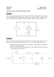
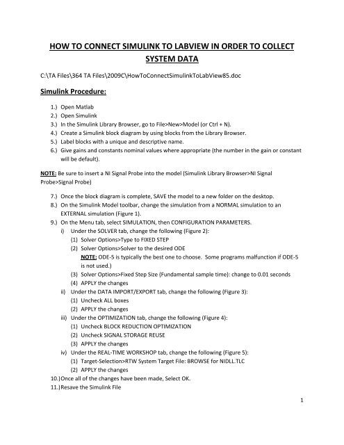
<strong>HOW</strong> <strong>TO</strong> <strong>CONNECT</strong> <strong>SIMUL<strong>IN</strong>K</strong> <strong>TO</strong> <strong>LABVIEW</strong> <strong>IN</strong> <strong>ORDER</strong> <strong>TO</strong> COLLECTSYSTEM DATAC:\TA Files\364 TA Files\2009C\HowToConnectSimulinkToLabView85.docSimulink Procedure:1.) Open Matlab2.) Open Simulink3.) In the Simulink Library Browser, go to File>New>Model (or Ctrl + N).4.) Create a Simulink block diagram by using blocks from the Library Browser.5.) Label blocks with a unique and descriptive name.6.) Give gains and constants nominal values where appropriate (the number in the gain or constantwill be default).NOTE: Be sure to insert a NI Signal Probe into the model (Simulink Library Browser>NI SignalProbe>Signal Probe)7.) Once the block diagram is complete, SAVE the model to a new folder on the desktop.8.) On the Simulink Model toolbar, change the simulation from a NORMAL simulation to anEXTERNAL simulation (Figure 1).9.) On the Menu tab, select SIMULATION, then CONFIGURATION PARAMETERS.i) Under the SOLVER tab, change the following (Figure 2):(1) Solver Options>Type to FIXED STEP(2) Solver Options>Solver to the desired ODENOTE: ODE‐5 is typically the best one to choose. Some programs malfunction if ODE‐5is not used.)(3) Solver Options>Fixed Step Size (Fundamental sample time): change to 0.01 seconds(4) APPLY the changesii) Under the DATA IMPORT/EXPORT tab, change the following (Figure 3):(1) Uncheck ALL boxes(2) APPLY the changesiii) Under the OPTIMIZATION tab, change the following (Figure 4):(1) Uncheck BLOCK REDUCTION OPTIMIZATION(2) Uncheck SIGNAL S<strong>TO</strong>RAGE REUSE(3) APPLY the changesiv) Under the REAL‐TIME WORKSHOP tab, change the following (Figure 5):(1) Target‐Selection>RTW System Target File: BROWSE for NIDLL.TLC(2) APPLY the changes10.) Once all of the changes have been made, Select OK.11.) Resave the Simulink File1
12.) Go to the MATLAB Main Screen13.) On the MATLAB toolbar, BROWSE the CURRENT DIREC<strong>TO</strong>RY for the file you saved your model toand select it (Figure 6).14.) Go back to the Simulink Model and BUILD the model by pressing Ctrl + B.15.) Matlab will then begin building the model. Your process can be checked by observing theCOMMAND W<strong>IN</strong>DOW.NOTE: If the final statement in the COMMAND W<strong>IN</strong>DOW after the data stops indicates a SUCCESS, youmay progress. If the final statement indicates anything else, your model may be incorrect or it maysimply need to be closed and then reopened.16.) RESAVE your Simulink model.<strong>LABVIEW</strong> Procedure:Note: Be sure that your PXI is up and running along with any power supply present.1.) Once your Simulink model has been built, go to <strong>LABVIEW</strong> and open a new VI. The defaultsetting is a Real Time VI; however, ensure this is the case.2.) Build your VI with the desired indicators and controls (Figure 8).3.) SAVE the file to the same location to which you saved the Simulink file.4.) Go to the <strong>LABVIEW</strong> toolbar and go to <strong>TO</strong>OLS and then SIT <strong>CONNECT</strong>ION MANAGER (Figure 7).5.) Once the MANAGER opens (Figure 9), select REAL‐TIME TARGET (Figure 10).6.) Once this is selected, a menu will pop‐up that asks you to SELECT THE MODEL DLL file from yourfolder. Search through your folder and select the .dll file (Figures 10).7.) Once the .dll file is selected, another menu will open that will ask you to ADD TARGETS ANDDEVICES (Figure 11).8.) Select existing device on remote subnet and enter IP address (you will find the IP address on thetop of remote DAQ).9.) Select OK.10.) Next BROWSE for your model by selecting the icon next to the CURRENT MODEL space (Figures12‐13).11.) Another menu will pop‐up called SELECT MODEL FILE. You need to go UP ONE LEVEL in orderto locate your Simulink .MDL file (Figures 12‐13).12.) Select the .MDL file and select OK (Figures 12‐13).13.) The .DLL and .MDL locations should be in the spaces provided under MODEL DLL and CURRENTMODEL, respectively (Figure 14).14.) Remaining in the SIT <strong>CONNECT</strong>ION MANAGER, select the MAPP<strong>IN</strong>GS tab near the top.15.) Double click the given spaces under MAPPED PARAMETER/SIGNAL. A menu will pop‐up whereyou are to select the correct Simulink parameter that goes along with the <strong>LABVIEW</strong> LABEL andTYPE.2
NOTE: This is a crucial step in that if the parameters are mapped wrong, the data will be incorrect or theVI will not function. This is why it is a good idea to give <strong>LABVIEW</strong> indicators and controls similar namesto your Simulink blocks that will be mapped (Figure 15).16.) Once your parameters have been mapped, click on the HARDWARE I/O tab.17.) Check the box next to NI DAQ (Figure 16).18.) Click the button that says CONFIGURE NI DAQ.19.) Clicking CONFIGURE NI DAQ will open another menu that says CONFIGURE NI DAQ DEVICES.The correct device should already be highlighted, so click NEXT (Figure 17).20.) Another menu will pop‐up that says CONFIGURE DAQ MAPP<strong>IN</strong>GS. This is where you select yourinput and output channels (Figure 18).21.) Select an input or output from DAQ CHANNELS that you will be using. Select the correspondingSimulink input/output from MODEL <strong>IN</strong>PUTS/OUTPUTS. When both boxes contain a highlighteditem, select ADD. This will map the input/output (Figures 19 and 20).22.) Continue step 21 for each input and output that your system will utilize.23.) Once all of your inputs/outputs have been mapped, click F<strong>IN</strong>ISH.24.) This will bring you back to the main SIT <strong>CONNECT</strong>ION MANAGER screen. At this point it wouldbe wise to double check all of your entries in the manager.25.) Click OK.26.) Labview will ask if you want to BUILD your VI. Select YES.27.) Labview will then build the VI. This may take a while.28.) Once Labview is done building, a new feature will be displayed on the front panel.NOTE: This is a control box which starts or stops your program in the collection of data. The RUN key(arrow) will still need to be clicked in order for the VI to work. To stop the VI or data collection, pressthe RED SQUARE (Figure 21).29.) The VI block diagram will also have new features. Many new blocks have been added in orderto help run the program. DO NOT ALTER THE BLOCKS UNLESS <strong>IN</strong>STRUCTED <strong>TO</strong> DO SO (Figure22).30.) In order to collect the data from different trials, a block needs to be added to the blockdiagram.31.) In the bottom CASE STRUCTURE, change the case from FALSE to TRUE (Figures 22 and 23).32.) Another CASE STRUCTURE will come up with all of your indicators (Figure 23).NOTE: Controls are not wired to the new block diagram features. This is normal and will not prevent thecontrols from working.3
33.) Make sure that all desired indicators are present (digital, charts, meters, etc.).34.) Right click the block diagram to bring up the FUNCTIONS PALLETTE.35.) Click on FILE I/O.36.) Select the block WRITE MEAS FILE (Figure 24).37.) A menu (CONFIGURE WRITE <strong>TO</strong> MEASUREMENT FILE) will pop‐up (Figure 25).38.) Under FILE NAME, select the BROWSE icon and search for the same file for which you havebeen saving all of your files thus far.39.) Enter a descriptive name into the provided space (CHOOSE A FILE <strong>TO</strong> WRITE). Do not end thefile name in a number (Figures 26 and 27).40.) Select OK once you have named and found a location for your file.41.) In the CONFIGURE WRITE <strong>TO</strong> MEASUREMENT FILE menu, under the section IF A FILE ALREADYEXISTS, choose USE NEXT AVAILABLE FILE NAME (Figure 28).42.) Under the section SEGMENT HEADERS, choose ONE HEADER ONLY (Figure 28).43.) Under the section X VALUE COLUMNS, choose ONE COLUMN ONLY (Figure 28).44.) Select OK.45.) Drop the block into the desired indicator case (or the indicators from which you want to collectyour data).46.) Connect a wire from the SIGNALS input of the block to the wire that goes into the desiredindicator (Figure 29).47.) Repeat steps 34 to 46 for each indicator you want to collect data from.48.) You can now run your program.Common Problems:‣ You have built and rebuilt the programs and cannot get your programs to function properly.o Possible solutions• Turn your PXI off for 20 seconds and then back on again. To ensure no transferof corrupt information, rebuild both your Labview and Simulink files once more.• You missed a step that is small and not noticeable.• Common mistakes:o You did not change your Simulink file from Normal to Externalo You did not set your main file as the location in MATLAB’sCurrent Directoryo You did not build your Simulink model (or the build failed).o You mapped the wrong Simulink blocks to the labviewindicators and controls.o You mapped to the wrong input and output channels.‣ Your program is working but the data is slow are corrupted.o Possible solutions/mistakes4
• You saved your files to a flash drive instead of to the computer. Resave yourfiles to the computer.Figure 15
Figure 26
Figure 37
Figure 48
Figure 5Figure 69
Figure 710
Figure 811
Figure 912
Figure 1013
Figure 1114
Figure 1215
Figure 1316
Figure 1417
Figure 1518
Figure 1619
Figure 1720
Figure 1821
Figure 1922
Figure 2023
Figure 2124
Figure 22Figure 2325
ureFig26
24Figure 2527
Figure 2628
Figure 2729
Figure 2830
Figure 2931