Rexroth MTA 200 Rexroth BTV 20.4A - Nuova Elva
Rexroth MTA 200 Rexroth BTV 20.4A - Nuova Elva
Rexroth MTA 200 Rexroth BTV 20.4A - Nuova Elva

You also want an ePaper? Increase the reach of your titles
YUMPU automatically turns print PDFs into web optimized ePapers that Google loves.
Industrial<br />
Hydraulics<br />
Electric Drives<br />
and Controls<br />
exroth IndraControl VCP 20<br />
<strong>Rexroth</strong> <strong>MTA</strong> <strong>200</strong><br />
<strong>Rexroth</strong> <strong>BTV</strong> <strong>20.4A</strong><br />
Project Planning Manual<br />
Linear Motion and<br />
Assembly Technologies Pneumatics<br />
Service<br />
Automation<br />
Mobile<br />
Hydraulics<br />
R911306076<br />
Edition 01
About this Documentation <strong>Rexroth</strong> <strong>BTV</strong> <strong>20.4A</strong><br />
Title<br />
Type of Documentation<br />
Document Typecode<br />
Internal File Reference<br />
Purpose of Documentation<br />
Record of Revisions<br />
Copyright<br />
Validity<br />
Published by<br />
Note<br />
<strong>Rexroth</strong> <strong>MTA</strong> <strong>200</strong><br />
<strong>Rexroth</strong> <strong>BTV</strong> <strong>20.4A</strong><br />
Project Planning Manual<br />
DOK-<strong>MTA</strong><strong>200</strong>-<strong>BTV</strong><strong>20.4A</strong>***-PR01-EN-P<br />
Document Number 120-1720-B317-01/EN<br />
This documentation describes the hardware components of the <strong>Rexroth</strong><br />
<strong>MTA</strong> <strong>200</strong> control system which are included in the operating PC<br />
<strong>BTV</strong> <strong>20.4A</strong>.<br />
Description Release<br />
Date<br />
Notes<br />
120-1720-B317-01/EN 06.<strong>200</strong>4 First issue<br />
© <strong>200</strong>4 Bosch <strong>Rexroth</strong> AG<br />
Copying this document, giving it to others and the use or communication<br />
of the contents thereof without express authority, are forbidden. Offenders<br />
are liable for the payment of damages. All rights are reserved in the event<br />
of the grant of a patent or the registration of a utility model or design<br />
(DIN 34-1).<br />
The specified data is for product description purposes only and may not<br />
be deemed to be guaranteed unless expressly confirmed in the contract.<br />
All rights are reserved with respect to the content of this documentation<br />
and the availability of the product.<br />
Bosch <strong>Rexroth</strong> AG<br />
Bgm.-Dr.-Nebel-Str. 2 • D-97816 Lohr a. Main<br />
Telephone +49 (0)93 52/40-0 • Tx 68 94 21 • Fax +49 (0)93 52/40-48 85<br />
http://www.boschrexroth.com/<br />
Dept. BRC/ESM5 (OI)<br />
Dept. BRC/ESM6 (DiHa)<br />
This document has been printed on chlorine-free bleached paper.<br />
DOK-<strong>MTA</strong><strong>200</strong>-<strong>BTV</strong><strong>20.4A</strong>***-PR01-EN-P
<strong>Rexroth</strong> <strong>BTV</strong> <strong>20.4A</strong> Contents I<br />
Contents<br />
1 Overview 1-1<br />
1.1 System Concept ........................................................................................................................... 1-1<br />
1.2 Regarding this Documentation ..................................................................................................... 1-1<br />
1.3 Additional Documentation............................................................................................................. 1-2<br />
1.4 Important Directions for Use......................................................................................................... 1-4<br />
Appropriate Use....................................................................................................................... 1-4<br />
Inappropriate Use .................................................................................................................... 1-5<br />
Notes for Electro Static Discharge........................................................................................... 1-5<br />
1.5 Safety Instructions for Electric Drives and Controls ..................................................................... 1-6<br />
Introduction .............................................................................................................................. 1-6<br />
Explanations ............................................................................................................................ 1-6<br />
Hazards by Improper Use........................................................................................................ 1-7<br />
General Information................................................................................................................. 1-8<br />
Protection Against Contact with Electrical Parts ..................................................................... 1-9<br />
Protection Against Electric Shock by Protective Low Voltage (PELV) .................................. 1-11<br />
Protection Against Dangerous Movements ........................................................................... 1-11<br />
Protection Against Magnetic and Electromagnetic Fields During Operation and<br />
Mounting ................................................................................................................................ 1-14<br />
Protection Against Contact with Hot Parts ............................................................................ 1-15<br />
Protection During Handling and Mounting............................................................................. 1-15<br />
Battery Safety ........................................................................................................................ 1-15<br />
Protection Against Pressurized Systems .............................................................................. 1-16<br />
2 Machine Operator Terminal <strong>BTV</strong> <strong>20.4A</strong> 2-1<br />
2.1 Brief Description ........................................................................................................................... 2-1<br />
Standard Configuration of the <strong>BTV</strong> 20.4 ................................................................................. 2-2<br />
Additional <strong>BTV</strong> <strong>20.4A</strong> Modules................................................................................................ 2-2<br />
Firmware and Software Configurations ................................................................................... 2-3<br />
2.2 Front Plate, Keyboard................................................................................................................... 2-4<br />
Floppy Disk Flap, Reset Button............................................................................................... 2-4<br />
Operating Display .................................................................................................................... 2-5<br />
Overview of Keys..................................................................................................................... 2-5<br />
Machine and PLC Function Keys ............................................................................................ 2-7<br />
Addressing via PLC ................................................................................................................. 2-8<br />
Replacing the Slide-in Strips ................................................................................................... 2-9<br />
2.3 Keyboard Layout......................................................................................................................... 2-11<br />
2.4 Technical Data............................................................................................................................ 2-15<br />
General Technical Data......................................................................................................... 2-15<br />
Ambient Conditions ............................................................................................................... 2-15<br />
DOK-<strong>MTA</strong><strong>200</strong>-<strong>BTV</strong><strong>20.4A</strong>***-PR01-EN-P
II Contents <strong>Rexroth</strong> <strong>BTV</strong> <strong>20.4A</strong><br />
Wear Parts............................................................................................................................. 2-16<br />
2.5 Measurements ............................................................................................................................ 2-17<br />
Housing Dimensions.............................................................................................................. 2-17<br />
2.6 Installation Dimensions............................................................................................................... 2-21<br />
2.7 Connections................................................................................................................................ 2-22<br />
General Connections............................................................................................................. 2-22<br />
Interfaces of NC CPU Card - Computer Configuration 45..................................................... 2-24<br />
LPT1 Printer Interface and SIS.............................................................................................. 2-26<br />
Internal Wiring........................................................................................................................ 2-28<br />
Sample Applications .............................................................................................................. 2-29<br />
2.8 Ordering Information................................................................................................................... 2-34<br />
Type Key................................................................................................................................ 2-34<br />
Configuration Type Key ......................................................................................................... 2-35<br />
Accessories ........................................................................................................................... 2-36<br />
2.9 Supplied Accessories (Scope of Delivery).................................................................................. 2-39<br />
3 PC CPU Configuration 45 3-1<br />
3.1 Brief Description ........................................................................................................................... 3-1<br />
3.2 Technical Data.............................................................................................................................. 3-1<br />
Electrical Specifications........................................................................................................... 3-1<br />
CPU and Memory Specifications............................................................................................. 3-1<br />
3.3 PhoenixBIOS Setup...................................................................................................................... 3-2<br />
Main PhoenixBIOS Setup Menu.............................................................................................. 3-3<br />
PhoenixBIOS Settings for the <strong>BTV</strong> 20.4.................................................................................. 3-4<br />
3.4 Installation of SO-DIMM Memory Modules................................................................................... 3-9<br />
3.5 Temporary Connection of Additional IDE Devices ..................................................................... 3-10<br />
Connection for Power Supply Cable...................................................................................... 3-10<br />
IDE Port ................................................................................................................................. 3-11<br />
4 PC CPU Configuration 44 4-1<br />
4.1 Brief Description ........................................................................................................................... 4-1<br />
4.2 Technical Data.............................................................................................................................. 4-2<br />
Electrical Specifications........................................................................................................... 4-2<br />
CPU and Memory Specifications............................................................................................. 4-2<br />
4.3 PhoenixBIOS Setup...................................................................................................................... 4-2<br />
PhoenixBIOS Settings of the NC CPU .................................................................................... 4-3<br />
5 NC Multifunction Card NCM02 5-1<br />
5.1 Brief Description ........................................................................................................................... 5-1<br />
5.2 Features........................................................................................................................................ 5-1<br />
5.3 Available Versions ........................................................................................................................ 5-2<br />
5.4 Interfaces ...................................................................................................................................... 5-3<br />
5.5 Coding and Component Diagrams ............................................................................................... 5-4<br />
+NCM0201 .............................................................................................................................. 5-4<br />
+NCM0202 .............................................................................................................................. 5-5<br />
+NCM0204 .............................................................................................................................. 5-6<br />
DOK-<strong>MTA</strong><strong>200</strong>-<strong>BTV</strong><strong>20.4A</strong>***-PR01-EN-P
<strong>Rexroth</strong> <strong>BTV</strong> <strong>20.4A</strong> Contents III<br />
5.6 Slot Brackets................................................................................................................................. 5-7<br />
CNC Fault (X21) ...................................................................................................................... 5-7<br />
Fast I/Os (X23) ........................................................................................................................ 5-8<br />
Status Indicators...................................................................................................................... 5-8<br />
5.7 Additional SERCOS Rings............................................................................................................ 5-9<br />
+NCMZ003 .............................................................................................................................. 5-9<br />
+NCMZ004 .............................................................................................................................. 5-9<br />
X24.* Transmitter................................................................................................................... 5-10<br />
X25.* Receiver....................................................................................................................... 5-10<br />
Status Indicators.................................................................................................................... 5-10<br />
Connections........................................................................................................................... 5-10<br />
NCM in the <strong>BTV</strong><strong>20.4A</strong> ........................................................................................................... 5-11<br />
5.8 Connection Cable ....................................................................................................................... 5-11<br />
Cable Specifications .............................................................................................................. 5-12<br />
5.9 NCIO Card .................................................................................................................................. 5-12<br />
General Information............................................................................................................... 5-12<br />
Slot Bracket ........................................................................................................................... 5-13<br />
X22 I/O Interface ................................................................................................................... 5-13<br />
Installation.............................................................................................................................. 5-15<br />
5.10 Phoenix Block I/O Module ILB IB 24 DI16 DO16 ....................................................................... 5-15<br />
Connection............................................................................................................................. 5-16<br />
Signal Assignment................................................................................................................. 5-16<br />
6 PLC Modules MTS-P01.2 and MTS-P02.2 6-1<br />
6.1 Brief Description ........................................................................................................................... 6-1<br />
6.2 Technical Data.............................................................................................................................. 6-3<br />
General Information................................................................................................................. 6-3<br />
Power Supply........................................................................................................................... 6-3<br />
EMC......................................................................................................................................... 6-3<br />
Interfaces ................................................................................................................................. 6-4<br />
6.3 Communication............................................................................................................................. 6-4<br />
PLC Inputs for the Machine Function Keys (X8) ..................................................................... 6-4<br />
Connection of <strong>BTV</strong> 20 PLC Function Keys (X12).................................................................... 6-4<br />
PLC Ready (X5)....................................................................................................................... 6-5<br />
COM Interface (X16) ............................................................................................................... 6-5<br />
BT Bus (X15) ........................................................................................................................... 6-5<br />
6.4 Commissioning ............................................................................................................................. 6-8<br />
Assembly ................................................................................................................................. 6-8<br />
Setting of Addresses ............................................................................................................... 6-8<br />
Battery ..................................................................................................................................... 6-9<br />
Status Information and Error Diagnosis .................................................................................. 6-9<br />
6.5 INTERBUS Master Connection .................................................................................................. 6-12<br />
Brief Description .................................................................................................................... 6-12<br />
Setting the I/O Address ......................................................................................................... 6-13<br />
Technical Data....................................................................................................................... 6-13<br />
Interface Assignment............................................................................................................. 6-14<br />
DOK-<strong>MTA</strong><strong>200</strong>-<strong>BTV</strong><strong>20.4A</strong>***-PR01-EN-P
IV Contents <strong>Rexroth</strong> <strong>BTV</strong> <strong>20.4A</strong><br />
6.6 PROFIBUS DP Connection ........................................................................................................ 6-15<br />
Brief Description of Master and Slave Connection................................................................ 6-15<br />
Setting I/O Addresses............................................................................................................ 6-16<br />
Status and Diagnosis Information.......................................................................................... 6-17<br />
Technical Data....................................................................................................................... 6-17<br />
Interface Assignment............................................................................................................. 6-18<br />
6.7 Connecting the Manual Operator Panel BTC 06........................................................................ 6-19<br />
6.8 Configurations............................................................................................................................. 6-21<br />
MTS-P0*.2-D2-B1-NN-NN-NN-FW ....................................................................................... 6-21<br />
MTS-P0*.2-D2-P1-NN-NN-NN-FW ....................................................................................... 6-22<br />
7 Tips and Tricks 7-1<br />
7.1 <strong>BTV</strong> Replacement......................................................................................................................... 7-1<br />
Hard Disk Image...................................................................................................................... 7-1<br />
Control Parameters (NCM Replacement) ............................................................................... 7-1<br />
CMOS Variables...................................................................................................................... 7-2<br />
PLC Retain Data (PLC Replacement)..................................................................................... 7-2<br />
8 Index 8-1<br />
9 Service & Support 9-1<br />
9.1 Helpdesk....................................................................................................................................... 9-1<br />
9.2 Service-Hotline ............................................................................................................................. 9-1<br />
9.3 Internet.......................................................................................................................................... 9-1<br />
9.4 Vor der Kontaktaufnahme... - Before contacting us... .................................................................. 9-1<br />
9.5 Kundenbetreuungsstellen - Sales & Service Facilities ................................................................. 9-2<br />
DOK-<strong>MTA</strong><strong>200</strong>-<strong>BTV</strong><strong>20.4A</strong>***-PR01-EN-P
<strong>Rexroth</strong> <strong>BTV</strong> <strong>20.4A</strong> Overview 1-1<br />
1 Overview<br />
1.1 System Concept<br />
1.2 Regarding this Documentation<br />
DOK-<strong>MTA</strong><strong>200</strong>-<strong>BTV</strong><strong>20.4A</strong>***-PR01-EN-P<br />
The consistent implementation of PC technology and the use of<br />
international industry standards has made it possible to fully integrate the<br />
control hardware in the operator PC while still ensuring simple and clear<br />
connections to drives and I/O peripherals.<br />
This integral solution guarantees that only defined and tested device<br />
configurations will be provided and supplied.<br />
The defined combination of various hardware components forms the<br />
basis of the <strong>MTA</strong> <strong>200</strong> control system. The operator PC itself as well as<br />
the components that are already installed in the operator PC on delivery<br />
are described in detail in this documentation.<br />
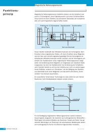
Fig. 1-1: Control architecture<br />
<strong>MTA</strong> Steuerungsarchitektur.jpg
1-2 Overview <strong>Rexroth</strong> <strong>BTV</strong> <strong>20.4A</strong><br />
1.3 Additional Documentation<br />
This includes the following components:<br />
Type Description Chapter<br />
<strong>BTV</strong> <strong>20.4A</strong> Operator PC with integrated control hardware 2<br />
ETXP3-700 PC-CPU 3<br />
ETXP3-400 NC-CPU 4<br />
NCM02 NC module with SERCOS interface 5<br />
NCIO I/O module for fast I/Os 5<br />
MTS-P Integrated PLC 6<br />
The openness of the control system allows the machine manufacturer to<br />
independently carry out application-specific hardware settings in the PC<br />
part, such as measured values recording, network connections, etc. In<br />
this case, the machine manufacturer must provide supplements to the<br />
hardware documentation.<br />
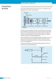
Fig. 1-2: System architecture<br />
Systemübersicht <strong>MTA</strong>.jpg<br />
DOK-<strong>MTA</strong><strong>200</strong>-<strong>BTV</strong><strong>20.4A</strong>***-PR01-EN-P
<strong>Rexroth</strong> <strong>BTV</strong> <strong>20.4A</strong> Overview 1-3<br />
DOK-<strong>MTA</strong><strong>200</strong>-<strong>BTV</strong><strong>20.4A</strong>***-PR01-EN-P<br />
The <strong>MTA</strong> <strong>200</strong> control system includes additional hardware components<br />
that are described in separate documents:<br />
Type Description Documentation<br />
BTA 20.4 Machine operator<br />
control panel<br />
DOK-SUPPL*-BTA20.4****-PR01-EN-P<br />
BTM 15 Machine user panel DOK-MTC<strong>200</strong>-BTM15******-PR02-EN-P<br />
BTM 16 Machine user panel DOK-MTC<strong>200</strong>-BTM16.1****-FKB1-EN-P<br />
PCK03 Drawer keyboard DOK-SUPPL*-PCK03.3****-PR01-DE-P<br />
BTC 06 Hand-held terminal DOK-SUPPL*-BTC06******-PR03-EN-P<br />
<strong>BTV</strong> 06 Mini control panel DOC-SUPPL*-<strong>BTV</strong>06.1****-PR02-EN-P<br />
RECO12 Switch cabinet I/Os for<br />
Interbus<br />
RMG12 Gateway module for I/O<br />
coupling<br />
DOK-CONTRL-RECO12.2***-PRJ2-EN-P<br />
DOK-CONTRL-RMG12.2****-PR02-EN-P<br />
RMC RECO analog module DOK-CONTRL-RMC12.2****-ANW1-EN-P<br />
SMx Protection type<br />
modules for Interbus<br />
RECO<br />
Inline<br />
RECO<br />
Fieldline<br />
Brief overview<br />
Interbus S system<br />
Profibus DP system<br />
Bus terminal, Interbus<br />
Bus terminal, Profibus<br />
Digital I/O modules<br />
Analog I/O modules<br />
Counter module<br />
Interbus devices<br />
Profibus devices<br />
DOK-CONTRL-SM*12.1****-PRJ2-EN-P<br />
DOK-CONTRL-R-IL*INLINE-KB02-EN-P<br />
DOK-CONTRL-R-IL*IBSSYS-AW02-EN-P<br />
DOK-CONTRL-R-IL*PBSSYS-AW02-EN-P<br />
DOK-CONTRL-R-IL*IBS-BK-FK04-DE-P<br />
DOK-CONTRL-R-IL*PB*-BK-FK02-EN-P<br />
DOK-CONTRL-R-IL*DIO***-FK05-EN-P<br />
DOK-CONTRL-R-IL*AIO***-FK02-EN-P<br />
DOK-CONTRL-R-IL*CNT***-AW02-EN-P<br />
DOK-CONTRL-RF-FLS-IB**-PR01-EN-P<br />
DOK-CONTRL-RF-FLS-PB**-PR01-EN-P<br />
The <strong>MTA</strong> <strong>200</strong> control system is supplemented by the intelligent digital<br />
drives of the Diax 04 and IndraDrive series.
1-4 Overview <strong>Rexroth</strong> <strong>BTV</strong> <strong>20.4A</strong><br />
1.4 Important Directions for Use<br />
Appropriate Use<br />
Introduction<br />
Bosch <strong>Rexroth</strong> products represent state-of-the-art developments and<br />
manufacturing. They are tested prior to delivery to ensure operating safety<br />
and reliability.<br />
The products may only be used in the manner that is defined as<br />
appropriate. If they are used in an inappropriate manner, then situations<br />
can develop that may lead to property damage or injury to personnel.<br />
Note: Bosch <strong>Rexroth</strong>, as manufacturer, is not liable for any damages<br />
resulting from inappropriate use. In such cases, the guarantee<br />
and the right to payment of damages resulting from<br />
inappropriate use are forfeited. The user alone carries all<br />
responsibility of the risks.<br />
Before using Bosch <strong>Rexroth</strong> products, make sure that all the prerequisites<br />
for appropriate use of the products are satisfied:<br />
• Personnel that in any way, shape or form uses our products must first<br />
read and understand the relevant safety instructions and be familiar<br />
with appropriate use.<br />
• If the product takes the form of hardware, then they must remain in<br />
their original state, in other words, no structural changes are permitted.<br />
It is not permitted to decompile software products or alter source<br />
codes.<br />
• Do not mount damaged or faulty products or use them in operation.<br />
• Make sure that the products have been installed in the manner<br />
described in the relevant documentation.<br />
Areas of use and application<br />
For <strong>BTV</strong> <strong>20.4A</strong> Bosch <strong>Rexroth</strong> defines appropriate use for installation into<br />
control panel, into the wall or door of a switch cabinet or directly into<br />
enclosure of machine tool.<br />
It may only be operated under the mounting and installation conditions<br />
specified in this documentation, in the position of use described, and<br />
under the ambient conditions specified (temperature, protection category,<br />
humidity, EMC, and the like).<br />
Note: <strong>BTV</strong> <strong>20.4A</strong> may only be used with the accessories and parts<br />
specified in this document. If a component has not been<br />
specifically named, then it may not be either mounted or<br />
connected. The same applies to cables and lines.<br />
Operation is only permitted in the specified configurations and<br />
combinations of components using the software and firmware<br />
as specified in the relevant function descriptions.<br />
Every <strong>MTA</strong> <strong>200</strong> control system has to be parameterized and programmed<br />
before start-up from qualified application staff.<br />
DOK-<strong>MTA</strong><strong>200</strong>-<strong>BTV</strong><strong>20.4A</strong>***-PR01-EN-P
<strong>Rexroth</strong> <strong>BTV</strong> <strong>20.4A</strong> Overview 1-5<br />
Inappropriate Use<br />
Notes for Electro Static Discharge<br />
DOK-<strong>MTA</strong><strong>200</strong>-<strong>BTV</strong><strong>20.4A</strong>***-PR01-EN-P<br />
Typical applications of <strong>MTA</strong> <strong>200</strong> control system are machine tools for<br />
following processing technologies:<br />
• Milling and grinding crankshafts<br />
• Grinding camshafts<br />
• Cogwheel processing<br />
Using the <strong>BTV</strong> <strong>20.4A</strong> outside of the above-referenced areas of application<br />
or under operating conditions other than described in the document and<br />
the technical data specified is defined as “inappropriate use".<br />
<strong>BTV</strong> <strong>20.4A</strong> may not be used if<br />
• they are subject to operating conditions that do not meet the above<br />
specified ambient conditions. This includes, for example, operation<br />
under water, in the case of extreme temperature fluctuations or<br />
extremely high maximum temperatures or if<br />
• Bosch <strong>Rexroth</strong> has not specifically released them for that intended<br />
purpose. Please note the specifications outlined in the general Safety<br />
Guidelines!<br />
In case of discharging via the controller or printed circuit boards, these<br />
components can be damaged by electrostatic charging of persons and/or<br />
tools. Therefore, please observe the following notes:<br />
CAUTION<br />
Risk of damage to the electronic components<br />
and deterioration of their operating safety by<br />
electrostatic charging!<br />
⇒ Bodies coming into contact with components and<br />
printed circuit boards must be discharged by<br />
grounding. Otherwise, errors in the controller can<br />
occur.<br />
Example for such bodies:<br />
• when soldering, the soldering gun<br />
• your own body (grounding by contact with a conductive, grounded<br />
object)<br />
• parts and tools (when deposited on a conductive surface)<br />
Components exposed to this risk may only be stored in conductive<br />
packaging.
1-6 Overview <strong>Rexroth</strong> <strong>BTV</strong> <strong>20.4A</strong><br />
1.5 Safety Instructions for Electric Drives and Controls<br />
Introduction<br />
Explanations<br />
Read these instructions before the initial startup of the equipment in order<br />
to eliminate the risk of bodily harm or material damage. Follow these<br />
safety instructions at all times.<br />
Do not attempt to install or start up this equipment without first reading all<br />
documentation provided with the product. Read and understand these<br />
safety instructions and all user documentation of the equipment prior to<br />
working with the equipment at any time. If you do not have the user<br />
documentation for your equipment, contact your local Bosch <strong>Rexroth</strong><br />
representative to send this documentation immediately to the person or<br />
persons responsible for the safe operation of this equipment.<br />
If the equipment is resold, rented or transferred or passed on to others,<br />
then these safety instructions must be delivered with the equipment.<br />
WARNING<br />
Improper use of this equipment, failure to follow<br />
the safety instructions in this document or<br />
tampering with the product, including disabling<br />
of safety devices, may result in material<br />
damage, bodily harm, electric shock or even<br />
death!<br />
The safety instructions describe the following degrees of hazard<br />
seriousness in compliance with ANSI Z535. The degree of hazard<br />
seriousness informs about the consequences resulting from noncompliance<br />
with the safety instructions.<br />
Warning symbol with signal<br />
word<br />
DANGER<br />
WARNING<br />
CAUTION<br />
Degree of hazard seriousness according<br />
to ANSI<br />
Death or severe bodily harm will occur.<br />
Death or severe bodily harm may occur.<br />
Bodily harm or material damage may occur.<br />
Fig. 1-3: Hazard classification (according to ANSI Z535)<br />
DOK-<strong>MTA</strong><strong>200</strong>-<strong>BTV</strong><strong>20.4A</strong>***-PR01-EN-P
<strong>Rexroth</strong> <strong>BTV</strong> <strong>20.4A</strong> Overview 1-7<br />
Hazards by Improper Use<br />
DOK-<strong>MTA</strong><strong>200</strong>-<strong>BTV</strong><strong>20.4A</strong>***-PR01-EN-P<br />
DANGER<br />
DANGER<br />
WARNING<br />
WARNING<br />
CAUTION<br />
CAUTION<br />
CAUTION<br />
High voltage and high discharge current!<br />
Danger to life or severe bodily harm by electric<br />
shock!<br />
Dangerous movements! Danger to life, severe<br />
bodily harm or material damage by<br />
unintentional motor movements!<br />
High electrical voltage due to wrong<br />
connections! Danger to life or bodily harm by<br />
electric shock!<br />
Health hazard for persons with heart<br />
pacemakers, metal implants and hearing aids in<br />
proximity to electrical equipment!<br />
Surface of machine housing could be extremely<br />
hot! Danger of injury! Danger of burns!<br />
Risk of injury due to improper handling! Bodily<br />
harm caused by crushing, shearing, cutting and<br />
mechanical shock or incorrect handling of<br />
pressurized systems!<br />
Risk of injury due to incorrect handling of<br />
batteries!
1-8 Overview <strong>Rexroth</strong> <strong>BTV</strong> <strong>20.4A</strong><br />
General Information<br />
• Bosch <strong>Rexroth</strong> AG is not liable for damages resulting from failure to<br />
observe the warnings provided in this documentation.<br />
• Read the operating, maintenance and safety instructions in your<br />
language before starting up the machine. If you find that you cannot<br />
completely understand the documentation for your product, please ask<br />
your supplier to clarify.<br />
• Proper and correct transport, storage, assembly and installation as<br />
well as care in operation and maintenance are prerequisites for<br />
optimal and safe operation of this equipment.<br />
• Only persons who are trained and qualified for the use and operation<br />
of the equipment may work on this equipment or within its proximity.<br />
• The persons are qualified if they have sufficient knowledge of the<br />
assembly, installation and operation of the equipment as well as an<br />
understanding of all warnings and precautionary measures noted in<br />
these instructions.<br />
• Furthermore, they must be trained, instructed and qualified to switch<br />
electrical circuits and equipment on and off in accordance with<br />
technical safety regulations, to ground them and to mark them<br />
according to the requirements of safe work practices. They must have<br />
adequate safety equipment and be trained in first aid.<br />
• Only use spare parts and accessories approved by the manufacturer.<br />
• Follow all safety regulations and requirements for the specific<br />
application as practiced in the country of use.<br />
• The equipment is designed for installation in industrial machinery.<br />
• The ambient conditions given in the product documentation must be<br />
observed.<br />
• Use only safety features and applications that are clearly and explicitly<br />
approved in the Project Planning Manual.<br />
For example, the following areas of use are not permitted: construction<br />
cranes, elevators used for people or freight, devices and vehicles to<br />
transport people, medical applications, refinery plants, transport of<br />
hazardous goods, nuclear applications, applications sensitive to high<br />
frequency, mining, food processing, control of protection equipment<br />
(also in a machine).<br />
• The information given in the documentation of the product with regard<br />
to the use of the delivered components contains only examples of<br />
applications and suggestions.<br />
The machine and installation manufacturer must<br />
• make sure that the delivered components are suited for his<br />
individual application and check the information given in this<br />
documentation with regard to the use of the components,<br />
• make sure that his application complies with the applicable safety<br />
regulations and standards and carry out the required measures,<br />
modifications and complements.<br />
• Startup of the delivered components is only permitted once it is sure<br />
that the machine or installation in which they are installed complies<br />
with the national regulations, safety specifications and standards of the<br />
application.<br />
DOK-<strong>MTA</strong><strong>200</strong>-<strong>BTV</strong><strong>20.4A</strong>***-PR01-EN-P
<strong>Rexroth</strong> <strong>BTV</strong> <strong>20.4A</strong> Overview 1-9<br />
DOK-<strong>MTA</strong><strong>200</strong>-<strong>BTV</strong><strong>20.4A</strong>***-PR01-EN-P<br />
• Operation is only permitted if the national EMC regulations for the<br />
application are met.<br />
The instructions for installation in accordance with EMC requirements<br />
can be found in the documentation "EMC in Drive and Control<br />
Systems".<br />
The machine or installation manufacturer is responsible for<br />
compliance with the limiting values as prescribed in the national<br />
regulations.<br />
• Technical data, connections and operational conditions are specified in<br />
the product documentation and must be followed at all times.<br />
Protection Against Contact with Electrical Parts<br />
Note: This section refers to equipment and drive components with<br />
voltages above 50 Volts.<br />
Touching live parts with voltages of 50 Volts and more with bare hands or<br />
conductive tools or touching ungrounded housings can be dangerous and<br />
cause electric shock. In order to operate electrical equipment, certain<br />
parts must unavoidably have dangerous voltages applied to them.
1-10 Overview <strong>Rexroth</strong> <strong>BTV</strong> <strong>20.4A</strong><br />
DANGER<br />
High electrical voltage! Danger to life, severe<br />
bodily harm by electric shock!<br />
⇒ Only those trained and qualified to work with or on<br />
electrical equipment are permitted to operate, maintain<br />
or repair this equipment.<br />
⇒ Follow general construction and safety regulations<br />
when working on high voltage installations.<br />
⇒ Before switching on power the ground wire must be<br />
permanently connected to all electrical units according<br />
to the connection diagram.<br />
⇒ Do not operate electrical equipment at any time, even<br />
for brief measurements or tests, if the ground wire is<br />
not permanently connected to the points of the<br />
components provided for this purpose.<br />
⇒ Before working with electrical parts with voltage higher<br />
than 50 V, the equipment must be disconnected from<br />
the mains voltage or power supply. Make sure the<br />
equipment cannot be switched on again unintended.<br />
⇒ The following should be observed with electrical drive<br />
and filter components:<br />
⇒ Wait five (5) minutes after switching off power to allow<br />
capacitors to discharge before beginning to work.<br />
Measure the voltage on the capacitors before<br />
beginning to work to make sure that the equipment is<br />
safe to touch.<br />
⇒ Never touch the electrical connection points of a<br />
component while power is turned on.<br />
⇒ Install the covers and guards provided with the<br />
equipment properly before switching the equipment on.<br />
Prevent contact with live parts at any time.<br />
⇒ A residual-current-operated protective device (RCD)<br />
must not be used on electric drives! Indirect contact<br />
must be prevented by other means, for example, by an<br />
overcurrent protective device.<br />
⇒ Electrical components with exposed live parts and<br />
uncovered high voltage terminals must be installed in a<br />
protective housing, for example, in a control cabinet.<br />
DOK-<strong>MTA</strong><strong>200</strong>-<strong>BTV</strong><strong>20.4A</strong>***-PR01-EN-P
<strong>Rexroth</strong> <strong>BTV</strong> <strong>20.4A</strong> Overview 1-11<br />
DOK-<strong>MTA</strong><strong>200</strong>-<strong>BTV</strong><strong>20.4A</strong>***-PR01-EN-P<br />
To be observed with electrical drive and filter components:<br />
DANGER<br />
High electrical voltage on the housing!<br />
High leakage current! Danger to life, danger of<br />
injury by electric shock!<br />
⇒ Connect the electrical equipment, the housings of all<br />
electrical units and motors permanently with the<br />
safety conductor at the ground points before power is<br />
switched on. Look at the connection diagram. This is<br />
even necessary for brief tests.<br />
⇒ Connect the safety conductor of the electrical<br />
equipment always permanently and firmly to the<br />
supply mains. Leakage current exceeds 3.5 mA in<br />
normal operation.<br />
⇒ Use a copper conductor with at least 10 mm² cross<br />
section over its entire course for this safety conductor<br />
connection!<br />
⇒ Prior to startups, even for brief tests, always connect<br />
the protective conductor or connect with ground wire.<br />
Otherwise, high voltages can occur on the housing<br />
that lead to electric shock.<br />
Protection Against Electric Shock by Protective Low Voltage (PELV)<br />
All connections and terminals with voltages between 0 and 50 Volts on<br />
<strong>Rexroth</strong> products are protective low voltages designed in accordance with<br />
international standards on electrical safety.<br />
WARNING<br />
Protection Against Dangerous Movements<br />
High electrical voltage due to wrong<br />
connections! Danger to life, bodily harm by<br />
electric shock!<br />
⇒ Only connect equipment, electrical components and<br />
cables of the protective low voltage type (PELV =<br />
Protective Extra Low Voltage) to all terminals and<br />
clamps with voltages of 0 to 50 Volts.<br />
⇒ Only electrical circuits may be connected which are<br />
safely isolated against high voltage circuits. Safe<br />
isolation is achieved, for example, with an isolating<br />
transformer, an opto-electronic coupler or when<br />
battery-operated.<br />
Dangerous movements can be caused by faulty control of the connected<br />
motors. Some common examples are:<br />
• improper or wrong wiring of cable connections<br />
• incorrect operation of the equipment components<br />
• wrong input of parameters before operation<br />
• malfunction of sensors, encoders and monitoring devices<br />
• defective components<br />
• software or firmware errors
1-12 Overview <strong>Rexroth</strong> <strong>BTV</strong> <strong>20.4A</strong><br />
Dangerous movements can occur immediately after equipment is<br />
switched on or even after an unspecified time of trouble-free operation.<br />
The monitoring in the drive components will normally be sufficient to avoid<br />
faulty operation in the connected drives. Regarding personal safety,<br />
especially the danger of bodily injury and material damage, this alone<br />
cannot be relied upon to ensure complete safety. Until the integrated<br />
monitoring functions become effective, it must be assumed in any case<br />
that faulty drive movements will occur. The extent of faulty drive<br />
movements depends upon the type of control and the state of operation.<br />
DOK-<strong>MTA</strong><strong>200</strong>-<strong>BTV</strong><strong>20.4A</strong>***-PR01-EN-P
<strong>Rexroth</strong> <strong>BTV</strong> <strong>20.4A</strong> Overview 1-13<br />
DOK-<strong>MTA</strong><strong>200</strong>-<strong>BTV</strong><strong>20.4A</strong>***-PR01-EN-P<br />
DANGER<br />
Dangerous movements! Danger to life, risk of<br />
injury, severe bodily harm or material damage!<br />
⇒ Ensure personal safety by means of qualified and<br />
tested higher-level monitoring devices or measures<br />
integrated in the installation. Unintended machine<br />
motion is possible if monitoring devices are disabled,<br />
bypassed or not activated.<br />
⇒ Pay attention to unintended machine motion or other<br />
malfunction in any mode of operation.<br />
⇒ Keep free and clear of the machine’s range of motion<br />
and moving parts. Possible measures to prevent<br />
people from accidentally entering the machine’s<br />
range of motion:<br />
- use safety fences<br />
- use safety guards<br />
- use protective coverings<br />
- install light curtains or light barriers<br />
⇒ Fences and coverings must be strong enough to<br />
resist maximum possible momentum, especially if<br />
there is a possibility of loose parts flying off.<br />
⇒ Mount the emergency stop switch in the immediate<br />
reach of the operator. Verify that the emergency stop<br />
works before startup. Don’t operate the machine if<br />
the emergency stop is not working.<br />
⇒ Isolate the drive power connection by means of an<br />
emergency stop circuit or use a starting lockout to<br />
prevent unintentional start.<br />
⇒ Make sure that the drives are brought to a safe<br />
standstill before accessing or entering the danger<br />
zone. Safe standstill can be achieved by switching off<br />
the power supply contactor or by safe mechanical<br />
locking of moving parts.<br />
⇒ Secure vertical axes against falling or dropping after<br />
switching off the motor power by, for example:<br />
- mechanically securing the vertical axes<br />
- adding an external braking/ arrester/ clamping<br />
mechanism<br />
- ensuring sufficient equilibration of the vertical axes<br />
The standard equipment motor brake or an external<br />
brake controlled directly by the drive controller are<br />
not sufficient to guarantee personal safety!
1-14 Overview <strong>Rexroth</strong> <strong>BTV</strong> <strong>20.4A</strong><br />
⇒ Disconnect electrical power to the equipment using a<br />
master switch and secure the switch against<br />
reconnection for:<br />
- maintenance and repair work<br />
- cleaning of equipment<br />
- long periods of discontinued equipment use<br />
⇒ Prevent the operation of high-frequency, remote<br />
control and radio equipment near electronics circuits<br />
and supply leads. If the use of such equipment<br />
cannot be avoided, verify the system and the<br />
installation for possible malfunctions in all possible<br />
positions of normal use before initial startup. If<br />
necessary, perform a special electromagnetic<br />
compatibility (EMC) test on the installation.<br />
Protection Against Magnetic and Electromagnetic Fields During<br />
Operation and Mounting<br />
Magnetic and electromagnetic fields generated near current-carrying<br />
conductors and permanent magnets in motors represent a serious health<br />
hazard to persons with heart pacemakers, metal implants and hearing<br />
aids.<br />
WARNING<br />
Health hazard for persons with heart<br />
pacemakers, metal implants and hearing aids in<br />
proximity to electrical equipment!<br />
⇒ Persons with heart pacemakers, hearing aids and<br />
metal implants are not permitted to enter the<br />
following areas:<br />
- Areas in which electrical equipment and parts are<br />
mounted, being operated or started up.<br />
- Areas in which parts of motors with permanent<br />
magnets are being stored, operated, repaired or<br />
mounted.<br />
⇒ If it is necessary for a person with a heart pacemaker<br />
to enter such an area, then a doctor must be<br />
consulted prior to doing so. Heart pacemakers that<br />
are already implanted or will be implanted in the<br />
future, have a considerable variation in their electrical<br />
noise immunity. Therefore there are no rules with<br />
general validity.<br />
⇒ Persons with hearing aids, metal implants or metal<br />
pieces must consult a doctor before they enter the<br />
areas described above. Otherwise, health hazards<br />
will occur.<br />
DOK-<strong>MTA</strong><strong>200</strong>-<strong>BTV</strong><strong>20.4A</strong>***-PR01-EN-P
<strong>Rexroth</strong> <strong>BTV</strong> <strong>20.4A</strong> Overview 1-15<br />
Protection Against Contact with Hot Parts<br />
DOK-<strong>MTA</strong><strong>200</strong>-<strong>BTV</strong><strong>20.4A</strong>***-PR01-EN-P<br />
CAUTION<br />
Protection During Handling and Mounting<br />
Battery Safety<br />
Housing surfaces could be extremely hot!<br />
Danger of injury! Danger of burns!<br />
⇒ Do not touch housing surfaces near sources of heat!<br />
Danger of burns!<br />
⇒ After switching the equipment off, wait at least ten<br />
(10) minutes to allow it to cool down before touching<br />
it.<br />
⇒ Do not touch hot parts of the equipment, such as<br />
housings with integrated heat sinks and resistors.<br />
Danger of burns!<br />
Under certain conditions, incorrect handling and mounting of parts and<br />
components may cause injuries.<br />
CAUTION<br />
Risk of injury by incorrect handling! Bodily<br />
harm caused by crushing, shearing, cutting and<br />
mechanical shock!<br />
⇒ Observe general installation and safety instructions<br />
with regard to handling and mounting.<br />
⇒ Use appropriate mounting and transport equipment.<br />
⇒ Take precautions to avoid pinching and crushing.<br />
⇒ Use only appropriate tools. If specified by the product<br />
documentation, special tools must be used.<br />
⇒ Use lifting devices and tools correctly and safely.<br />
⇒ For safe protection wear appropriate protective<br />
clothing, e.g. safety glasses, safety shoes and safety<br />
gloves.<br />
⇒ Never stand under suspended loads.<br />
⇒ Clean up liquids from the floor immediately to prevent<br />
slipping.<br />
Batteries contain reactive chemicals in a solid housing. Inappropriate<br />
handling may result in injuries or material damage.<br />
CAUTION<br />
Risk of injury by incorrect handling!<br />
⇒ Do not attempt to reactivate discharged batteries by<br />
heating or other methods (danger of explosion and<br />
cauterization).<br />
⇒ Never charge non-chargeable batteries (danger of<br />
leakage and explosion).<br />
⇒ Never throw batteries into a fire.<br />
⇒ Do not dismantle batteries.<br />
⇒ Do not damage electrical components installed in the<br />
equipment.
1-16 Overview <strong>Rexroth</strong> <strong>BTV</strong> <strong>20.4A</strong><br />
Protection Against Pressurized Systems<br />
Note: Be aware of environmental protection and disposal! The<br />
batteries contained in the product should be considered as<br />
hazardous material for land, air and sea transport in the sense<br />
of the legal requirements (danger of explosion). Dispose<br />
batteries separately from other waste. Observe the legal<br />
requirements in the country of installation.<br />
Certain motors and drive controllers, corresponding to the information in<br />
the respective Project Planning Manual, must be provided with<br />
pressurized media, such as compressed air, hydraulic oil, cooling fluid<br />
and cooling lubricant supplied by external systems. Incorrect handling of<br />
the supply and connections of pressurized systems can lead to injuries or<br />
accidents. In these cases, improper handling of external supply systems,<br />
supply lines or connections can cause injuries or material damage.<br />
CAUTION<br />
Danger of injury by incorrect handling of<br />
pressurized systems !<br />
⇒ Do not attempt to disassemble, to open or to cut a<br />
pressurized system (danger of explosion).<br />
⇒ Observe the operation instructions of the respective<br />
manufacturer.<br />
⇒ Before disassembling pressurized systems, release<br />
pressure and drain off the fluid or gas.<br />
⇒ Use suitable protective clothing (for example safety<br />
glasses, safety shoes and safety gloves)<br />
⇒ Remove any fluid that has leaked out onto the floor<br />
immediately.<br />
Note: Environmental protection and disposal! The media used in the<br />
operation of the pressurized system equipment may not be<br />
environmentally compatible. Media that are damaging the<br />
environment must be disposed separately from normal waste.<br />
Observe the legal requirements in the country of installation.<br />
DOK-<strong>MTA</strong><strong>200</strong>-<strong>BTV</strong><strong>20.4A</strong>***-PR01-EN-P
<strong>Rexroth</strong> <strong>BTV</strong> <strong>20.4A</strong> Machine Operator Terminal <strong>BTV</strong> <strong>20.4A</strong> 2-1<br />
2 Machine Operator Terminal <strong>BTV</strong> <strong>20.4A</strong><br />
2.1 Brief Description<br />
L 1-8 machine<br />
function keys<br />
Line in strips<br />
for Key lable<br />
HALT<br />
NACH<br />
TAKTENDE<br />
OPERATOR PROG<br />
MASCHINE<br />
STOP<br />
EINHEIT<br />
STOP<br />
DOK-<strong>MTA</strong><strong>200</strong>-<strong>BTV</strong><strong>20.4A</strong>***-PR01-EN-P<br />
L1<br />
L2<br />
L3<br />
L4<br />
L5<br />
L6<br />
L7<br />
L8<br />
EINHEIT<br />
STOP<br />
The <strong>BTV</strong> <strong>20.4A</strong> is a PC-based machine operator terminal that also<br />
contains all the hardware of the <strong>MTA</strong> <strong>200</strong> control system. Depending on<br />
the configuration, slots are available for customer-specific extensions in<br />
the PC bus.<br />
Note: This chapter describes the <strong>BTV</strong> <strong>20.4A</strong> in its version for the<br />
<strong>MTA</strong> <strong>200</strong> control system. The <strong>BTV</strong> 20 can also be procured as<br />
a pure industrial PC, as a PC with integrated PLC, or as a PC<br />
with integrated MTC<strong>200</strong> control system. These versions are<br />
described in the general <strong>BTV</strong> 20 documentation<br />
DOK-MTC<strong>200</strong>-<strong>BTV</strong>20.3****-PR03-EN-P.<br />
The figure below shows the structure of the <strong>BTV</strong> 20.4 front plate:<br />
F2 F3<br />
OP2<br />
ZUM<br />
WERKZEUG-<br />
WECHSEL<br />
F4 F5 F6 F7 F8 F9<br />
OP3 OP4 OP5 OP6 OP7 OP8 OP9<br />
SONDER-<br />
FUKTIONEN<br />
FEHLER<br />
LÖSCHEN<br />
SYSTEM<strong>200</strong><br />
Fig. 2-1: <strong>BTV</strong> 20.4 front plate<br />
R1<br />
R2<br />
R3<br />
R4<br />
R5<br />
R6<br />
R7<br />
R8<br />
TEMP HD POWER<br />
7 8 9 N + -<br />
< F1 F1 F10 F10< > - +<br />
4 5<br />
6<br />
. .<br />
.<br />
PROG<br />
SFT<br />
PROG<br />
- SHIFT<br />
,<br />
1<br />
2<br />
3<br />
,<br />
,<br />
NEXT INFO TAB INS DEL<br />
NEXT INFO TAB INS DEL<br />
0<br />
CTRL ALT<br />
SP SP<br />
CTRL ALT<br />
ESC<br />
OK<br />
Machine<br />
control keys<br />
R 1-8 machine<br />
function keys<br />
3.5-in floppy disk<br />
drive / Smart card<br />
Connector for<br />
ext. keyboard + mouse<br />
Status indicators<br />
POWER<br />
HD<br />
TEMP<br />
=Power supply:<br />
ON<br />
= Hard disk access<br />
= Overtemperature<br />
indicator<br />
Front.FH7<br />
The front plate consists of a 4 mm-thick aluminum plate with beveled<br />
edges. It is coated with a chemically resistant polyester film with an<br />
imprint that covers the entire front plate. The integrated 10.4" TFT color<br />
display provides for excellent visualization of the data. A 3.5" disk drive, a<br />
reset button and a connection for an external keyboard or mouse are<br />
located behind the flap for floppy disks. Three LEDs indicate the operating<br />
status of the <strong>BTV</strong> 20.4. A key-operated switch locks safety functions.
2-2 Machine Operator Terminal <strong>BTV</strong> <strong>20.4A</strong> <strong>Rexroth</strong> <strong>BTV</strong> <strong>20.4A</strong><br />
Standard Configuration of the <strong>BTV</strong> 20.4<br />
Additional <strong>BTV</strong> <strong>20.4A</strong> Modules<br />
Furthermore, the <strong>BTV</strong> 20.4 is equipped with an extensive applicationoriented<br />
function keyboard with the following keys:<br />
• Machine function keys<br />
• Function and operation keys<br />
• PLC function keys with intermediate stages<br />
• Keypad<br />
For further information regarding the functioning and assignment of the<br />
individual keys as well as the front plate elements discussed above, see<br />
the description of the front plate in chapter 4.<br />
• Pentium SLOT CPU, min. 700 MHz, with integrated graphics<br />
controller, 4 MB screen memory and Ethernet connection<br />
• Either 128 or 256 MB RAM<br />
• At least 3 GB hard disk<br />
• 3.5" floppy disk drive<br />
• 10.4" TFT color display<br />
• 115 - 230 V AC power pack<br />
In the model functioning as an <strong>MTA</strong> <strong>200</strong> control system, the <strong>BTV</strong> <strong>20.4A</strong> is<br />
equipped with the following additional modules:<br />
• NC CPU Pentium Slot CPU with 400 MHz<br />
• NCM NC module with one SERCOS interface<br />
• NCZ module with one or two additional SERCOS interfaces<br />
• PLC module with INTERBUS-S or Profibus master connection<br />
• NIO module for parallel connection of fast I/Os<br />
All currently existing configurations can be found in the configuration type<br />
key (see page 2-35).<br />
All the listed modules are described in detail in the following chapters.<br />
DOK-<strong>MTA</strong><strong>200</strong>-<strong>BTV</strong><strong>20.4A</strong>***-PR01-EN-P
<strong>Rexroth</strong> <strong>BTV</strong> <strong>20.4A</strong> Machine Operator Terminal <strong>BTV</strong> <strong>20.4A</strong> 2-3<br />
Firmware and Software Configurations<br />
DOK-<strong>MTA</strong><strong>200</strong>-<strong>BTV</strong><strong>20.4A</strong>***-PR01-EN-P<br />
Operating System<br />
Due to licensing reasons, the <strong>BTV</strong> 20.4 is delivered only with a<br />
preinstalled operating system.<br />
The following firmware configurations are available for the <strong>BTV</strong> <strong>20.4A</strong>:<br />
Firmware type Description<br />
FWA-<strong>BTV</strong>*44-WNT-04VRS-DE-OEM WindowsNT 4.0 German<br />
FWA-<strong>BTV</strong>*44-WNT-04VRS-EN-OEM WindowsNT 4.0 English<br />
FWA-<strong>BTV</strong>*44-WNT-05VRS-DE-OEM Windows<strong>200</strong>0 German<br />
FWA-<strong>BTV</strong>*44-WNT-05VRS-EN-OEM Windows<strong>200</strong>0 English<br />
Fig. 2-2: Firmware configurations for <strong>MTA</strong> <strong>200</strong><br />
The SWA, SWL, SWS and/or SWP ordered together with the <strong>BTV</strong> <strong>20.4A</strong><br />
are installed on the <strong>BTV</strong> prior to delivery.<br />
Bosch <strong>Rexroth</strong> does not pre-install any software requiring export<br />
authorization; the final customer has to install this type of software<br />
subsequently when commissioning the <strong>BTV</strong> 20.
2-4 Machine Operator Terminal <strong>BTV</strong> <strong>20.4A</strong> <strong>Rexroth</strong> <strong>BTV</strong> <strong>20.4A</strong><br />
2.2 Front Plate, Keyboard<br />
Floppy Disk Flap, Reset Button<br />
Under the floppy disk flap, there is a reset button, which can be reached<br />
using a thin object (pen, etc.), as well as the connection for an external<br />
keyboard. This connection can be used as a service interface if the<br />
PCK03 drawer keyboard is not available.<br />
Note: When the reset button is pressed, all open applications are<br />
terminated without saving and the computer is rebooted.<br />
CAUTION<br />
In the <strong>MTA</strong> <strong>200</strong>, the reset button affects only the PC part<br />
of the control. The NC part is initially unaffected and<br />
continues to run. When booting the PC part, however,<br />
the communication task to the NC will get stuck - now the<br />
<strong>BTV</strong> must be restarted.<br />
⇒ For that reason, it is recommended that the reset<br />
button not be used with the <strong>MTA</strong>.<br />
STEM<strong>200</strong><br />
Fig. 2-3: Position of the reset button<br />
R1<br />
R2<br />
R3<br />
R4<br />
R5<br />
R6<br />
R7<br />
R8<br />
TEMP HD POWER<br />
Reset button<br />
Floppyklappe.FH7<br />
Note: When you use the disk drive, keep the floppy disk flap open.<br />
When the flap is closed, the diskette may be ejected, leading<br />
to write and read errors.<br />
DOK-<strong>MTA</strong><strong>200</strong>-<strong>BTV</strong><strong>20.4A</strong>***-PR01-EN-P
<strong>Rexroth</strong> <strong>BTV</strong> <strong>20.4A</strong> Machine Operator Terminal <strong>BTV</strong> <strong>20.4A</strong> 2-5<br />
Operating Display<br />
Overview of Keys<br />
L1<br />
M9<br />
L2<br />
M10<br />
L3<br />
M11<br />
L4<br />
M12<br />
L5<br />
M13<br />
L6<br />
M14<br />
L7<br />
M15<br />
L8<br />
M16<br />
OPERATOR PROG<br />
F2 F3<br />
OP2<br />
Indramat<br />
F2 F3<br />
OP2<br />
DOK-<strong>MTA</strong><strong>200</strong>-<strong>BTV</strong><strong>20.4A</strong>***-PR01-EN-P<br />
Under the floppy disk flap, there are 3 LEDs with the following<br />
explanations:<br />
Temp Temperature monitoring<br />
Power Lights up when the <strong>BTV</strong> 20 is supplied with voltage and is<br />
switched on<br />
HDD Lights up during disk access<br />
R8<br />
7<br />
<<br />
Fig. 2-4: Operating displays<br />
F4 F5 F6 F7 F8 F9<br />
OP3 OP4 OP5 OP6 OP7 OP8 OP9<br />
R1<br />
M1<br />
R2<br />
M2<br />
R3<br />
M3<br />
R4<br />
M4<br />
R5<br />
M5<br />
R6<br />
M6<br />
R7<br />
M7<br />
R8<br />
M8<br />
TEMP<br />
TEMP HD POWER<br />
8<br />
F1<br />
TEMP HD POWER<br />
9<br />
F10<br />
SYSTEM<strong>200</strong> <strong>BTV</strong>20<br />
7 8 9 N +<br />
7<br />
<<br />
8 9 N +<br />
<<br />
F1 F10 -<br />
F1 F10 > -<br />
4 5 6 .<br />
4 5 6 .<br />
SFT<br />
PROG<br />
-<br />
,<br />
1 2 3 ,<br />
DEL<br />
NEXT INFO TAB INS INS<br />
0<br />
SP SP<br />
HD POWER<br />
CTRL ALT<br />
ESC<br />
OK<br />
F4 F5 F6 F7 F8 F9<br />
OP3 OP4 OP5 OP6 OP7 OP8 OP9<br />
Fig. 2-5: Position of OP and F keys<br />
N<br />
<<br />
<<br />
+ -<br />
ESC<br />
Key pad<br />
7 8 9 N +<br />
< F1 F10 -<br />
4<br />
PROG<br />
1<br />
NEXT<br />
5<br />
2<br />
INFO<br />
0<br />
SP<br />
6<br />
3<br />
TAB<br />
.<br />
,<br />
-<br />
INS<br />
<<br />
CTRL ALT<br />
OK<br />
Betriebsanz.FH7<br />
SFT<br />
DEL<br />
Function keys<br />
Operation keys<br />
OP_Tast1.FH7<br />
The second function of keys with dual assignments can be triggered by<br />
pressing the Shift key at the same time.
2-6 Machine Operator Terminal <strong>BTV</strong> <strong>20.4A</strong> <strong>Rexroth</strong> <strong>BTV</strong> <strong>20.4A</strong><br />
Note: The OP key row can also be individually labeled with a slide-in<br />
strip (see page 2-9).<br />
Explanation and Replication of Keys<br />
The <strong>BTV</strong> 20 keys can be replicated on a PC keyboard using the following<br />
key combinations:<br />
Key on <strong>BTV</strong> 20.3 Corresponding key on standard<br />
keyboard<br />
OP2<br />
through<br />
OP9<br />
PROG<br />
NEXT<br />
INFO<br />
Maximize in cursor center<br />
Menu<br />
Change windows<br />
Grasp window<br />
CTRL + SHIFT + ALT + F2<br />
CTRL + SHIFT + ALT + F9<br />
CTRL + SHIFT + ALT + Q<br />
CTRL + SHIFT + ALT + N<br />
ALT<br />
Fig. 2-6: Key combinations for <strong>BTV</strong> 20 keys<br />
CTRL + SHIFT + ALT + I<br />
CTRL + SHIFT + ALT + M<br />
CTRL + F6<br />
CTRL + F7<br />
DOK-<strong>MTA</strong><strong>200</strong>-<strong>BTV</strong><strong>20.4A</strong>***-PR01-EN-P
<strong>Rexroth</strong> <strong>BTV</strong> <strong>20.4A</strong> Machine Operator Terminal <strong>BTV</strong> <strong>20.4A</strong> 2-7<br />
Machine and PLC Function Keys<br />
Machine function keys<br />
on the left<br />
L1<br />
L2<br />
L3<br />
L4<br />
L5<br />
L6<br />
L7<br />
L8<br />
OPERATOR PROG<br />
%Q*.1.6<br />
%I*.1.6<br />
%Q*.1.7<br />
%I*.1.7<br />
DOK-<strong>MTA</strong><strong>200</strong>-<strong>BTV</strong><strong>20.4A</strong>***-PR01-EN-P<br />
L1<br />
M9<br />
L2<br />
M10<br />
L3<br />
M11<br />
L4<br />
M12<br />
L5<br />
M13<br />
L6<br />
M14<br />
L7<br />
M15<br />
L8<br />
M16<br />
OPERATOR PROG<br />
Indramat<br />
%I*.0.0<br />
%Q*.0.0<br />
%I*.0.7<br />
%Q*.0.7<br />
F2 F3<br />
OP2<br />
F4 F5 F6 F7 F8 F9<br />
OP3 OP4 OP5 OP6 OP7 OP8 OP9<br />
%I*.0.1<br />
%Q*.0.1<br />
%I*.1.0<br />
%Q*.1.0<br />
SYSTEM<strong>200</strong> <strong>BTV</strong>20<br />
R1<br />
M1<br />
R2<br />
M2<br />
R3<br />
M3<br />
R4<br />
M4<br />
R5<br />
M5<br />
R6<br />
M6<br />
R7<br />
M7<br />
R8<br />
M8<br />
TEMP<br />
TEMP HD POWER<br />
7 8 9 N +<br />
7<br />
<<br />
8 9 N +<br />
<<br />
F1 F10 -<br />
F1 F10 > -<br />
4 5 6 .<br />
4 5 6 .<br />
SFT SFT<br />
PROG<br />
-<br />
,<br />
1 2<br />
3 ,<br />
DEL<br />
NEXT INFO TAB INS INS<br />
0<br />
SP SP<br />
HD POWER<br />
CTRL ALT<br />
ESC<br />
OK<br />
PLC function keys<br />
(Addressing)<br />
%I*.0.2<br />
%Q*.0.2<br />
%I*.1.1<br />
%Q*.1.1<br />
%I*.0.3<br />
%Q*.0.3<br />
%I*.1.2<br />
%Q*.1.2<br />
%I*.0.4<br />
%Q*.0.4<br />
%I*.1.3<br />
%Q*.1.3<br />
<<br />
Machine function keys<br />
on the right<br />
%I*.0.5<br />
%Q*.0.5<br />
%I*.1.4<br />
%Q*.1.4<br />
Fig. 2-7: Position of machine and PLC function keys<br />
Machine Function Keys<br />
R1<br />
R2<br />
R3<br />
R4<br />
R5<br />
R6<br />
R7<br />
R8<br />
%I*.0.6<br />
%Q*.0.6<br />
%I*.1.5<br />
%Q*.1.5<br />
S1-7<br />
S8-14<br />
M_plc_tasten.FH7<br />
The machine function keys are implemented in the PLC as direct, hardwired<br />
inputs which are triggered with an absolute address. These keys<br />
are used to start projected PLC or CNC movements.<br />
PLC Function Keys<br />
Furthermore, the <strong>BTV</strong> 20 has LEDs that can be labeled using slide-in<br />
strips. Together with the key-operated switch, these keys are connected<br />
to the PLC; they replace the standard switching elements for fixed PLC<br />
functions such as ‘Basic setting’ or ‘Stop after end of cycle’, etc.
2-8 Machine Operator Terminal <strong>BTV</strong> <strong>20.4A</strong> <strong>Rexroth</strong> <strong>BTV</strong> <strong>20.4A</strong><br />
Addressing via PLC<br />
Alternatives with address<br />
constants<br />
Machine Function Keys<br />
In <strong>BTV</strong>s with an integrated PLC, the machine function keys are connected<br />
directly to the PLC; as a result, they can be addressed directly via the<br />
PLC program.<br />
Machine function keys Address<br />
L1 %I0.1480.0<br />
L2 %I0.1480.1<br />
L3 %I0.1480.2<br />
L4 %I0.1480.3<br />
L5 %I0.1480.4<br />
L6 %I0.1480.5<br />
L7 %I0.1480.6<br />
L8 %I0.1480.7<br />
R1 %I0.1481.0<br />
R2 %I0.1481.1<br />
R3 %I0.1481.2<br />
R4 %I0.1481.3<br />
R5 %I0.1481.4<br />
R6 %I0.1481.5<br />
R7 %I0.1481.6<br />
R8 %I0.1481.7<br />
Fig. 2-8: Addressing of machine function keys<br />
Address constants can be used instead of direct addressing for Bosch<br />
<strong>Rexroth</strong> firmware data types.<br />
Machine function keys, left/right<br />
PLC program identifier Address constants Data type<br />
MFT_L A#iMFK_L MFK_L<br />
MFT_R A#iMFK_R MFK_R<br />
Fig. 2-9: Addressing with address constants<br />
Data type MFK_L contains the elements L1, L2,..., L8 of type BOOL.<br />
Data type MFK_R contains the elements R1, R2,..., R8 of type BOOL.<br />
PLC program example: MFT_L.L1<br />
DOK-<strong>MTA</strong><strong>200</strong>-<strong>BTV</strong><strong>20.4A</strong>***-PR01-EN-P
<strong>Rexroth</strong> <strong>BTV</strong> <strong>20.4A</strong> Machine Operator Terminal <strong>BTV</strong> <strong>20.4A</strong> 2-9<br />
Replacing the Slide-in Strips<br />
DOK-<strong>MTA</strong><strong>200</strong>-<strong>BTV</strong><strong>20.4A</strong>***-PR01-EN-P<br />
PLC Function Keys<br />
PLC function key Address key Address LED<br />
S1 (see illustration) %I*.0.0 %Q*.0.0<br />
S2 %I*.0.1 %Q*.0.1<br />
S3 %I*.0.2 %Q*.0.2<br />
S4 %I*.0.3 %Q*.0.3<br />
S5 %I*.0.4 %Q*.0.4<br />
S6 %I*.0.5 %Q*.0.5<br />
S7 %I*.0.6 %Q*.0.6<br />
S8 %I*.0.7 %Q*.0.7<br />
S9 %I*.1.0 %Q*.1.0<br />
S10 %I*.1.1 %Q*.1.1<br />
S11 %I*.1.2 %Q*.1.2<br />
S12 %I*.1.3 %Q*.1.3<br />
S13 %I*.1.4 %Q*.1.4<br />
S14 %I*.1.5 %Q*.1.5<br />
Key-operated switch,<br />
left (Operator)<br />
Key-operated switch,<br />
right (Prog)<br />
Fig. 2-10: Addressing PLC function keys<br />
%I*.1.6 %Q*.1.6<br />
%I*.1.7 %Q*.1.7<br />
Two free logical addresses within the PLC configuration are to be<br />
assigned for inputs and outputs.<br />
The 14 PLC function keys on the front of the <strong>BTV</strong> 20 can be labeled using<br />
slide-in strips. The row of keys above the PLC function keys (OP2 - OP9)<br />
are also freely configurable using slide-in strips.<br />
The strips, which are already inserted when the machine is delivered, can<br />
be replaced as desired. Preprinted strips as well as a diskette with<br />
templates so that you can create your own key labels are also included in<br />
the scope of delivery. A description of how to replace the slide-in strips is<br />
provided below.
2-10 Machine Operator Terminal <strong>BTV</strong> <strong>20.4A</strong> <strong>Rexroth</strong> <strong>BTV</strong> <strong>20.4A</strong><br />
Aperture for<br />
changing the<br />
Slide-in labels<br />
Fig. 2-11: Position of slide-in strip openings<br />
Procedure for Replacing Slide-in Strips<br />
Einschub.FH7<br />
1. Cut the strips that are supplied or that you have created yourself<br />
along the lines.<br />
2. Chamfer the corners at the right end of each strip to simplify insertion.<br />
3. Now carefully insert the strip.<br />
a) To do this, hold the strip at an acute angle to the front plate and<br />
thread it into the housing opening (see Fig. 2-12, part A).<br />
Note: The slide-in strip must be inserted into the pocket of the gluedon<br />
front membrane (see Fig. 2-12). If the strip is not supposed<br />
to be in the membrane pocket, insertion is possible only up to<br />
the first stage of the front plate.<br />
b) Slowly push the strip further into the membrane pocket. Do not kink<br />
the paper strip (see Fig. 2-12, part B).<br />
DOK-<strong>MTA</strong><strong>200</strong>-<strong>BTV</strong><strong>20.4A</strong>***-PR01-EN-P
<strong>Rexroth</strong> <strong>BTV</strong> <strong>20.4A</strong> Machine Operator Terminal <strong>BTV</strong> <strong>20.4A</strong> 2-11<br />
A<br />
2.3 Keyboard Layout<br />
External keyboard<br />
DOK-<strong>MTA</strong><strong>200</strong>-<strong>BTV</strong><strong>20.4A</strong>***-PR01-EN-P<br />
B<br />
Fig. 2-12: Slide-in strip replacement<br />
Einschub01.FH7<br />
4. Insert the strip up to the stop.<br />
5. Check the front to see whether the label is above the key.<br />
If the alignment is not yet perfect, remove the strip, shorten it on the<br />
right side and insert it again.<br />
6. The projecting remainder may not be cut off to the degree that<br />
subsequent replacement of the slide-in strip is impossible.<br />
In order to ensure problem-free functioning of both the internal and the<br />
external keyboards on the <strong>BTV</strong> 20, a few things must be taken into<br />
account.<br />
When it is delivered, the keyboard driver and thus the keyboard layout of<br />
the desired language is already correctly configured under Windows (this<br />
is the language of the installed operating system). The connection of an<br />
external keyboard, such as the PCK03 drawer keyboard, is also correctly<br />
preset when the device is delivered. Changes are required only if a<br />
keyboard is connected whose keyboard layout does not agree with the<br />
preset keyboard language. At the same time, the software of the internal<br />
membrane keyboard on the front of the <strong>BTV</strong> 20 must be readapted. How<br />
this change is to be made is described below.<br />
Changing the Keyboard Language<br />
To adapt the external keyboard, the following steps must be carried out:<br />
1. Call menu item "Keyboard" in the Windows NT control panel.<br />
Path: Start - Settings - Control Panel - Keyboard
2-12 Machine Operator Terminal <strong>BTV</strong> <strong>20.4A</strong> <strong>Rexroth</strong> <strong>BTV</strong> <strong>20.4A</strong><br />
Fig. 2-13: Control panel icon "Keyboard"<br />
Systemstg01.bmp<br />
2. Switch to the "Input" tab.<br />
The preset keyboard layout is displayed here.<br />
3. Press the "Add…" button.<br />
4. Select the language to be used for the external keyboard from the list<br />
(input locale).<br />
Use the default characteristics for this input locale.<br />
Fig. 2-14: "Input" tab<br />
Eingabe.bmp<br />
DOK-<strong>MTA</strong><strong>200</strong>-<strong>BTV</strong><strong>20.4A</strong>***-PR01-EN-P
<strong>Rexroth</strong> <strong>BTV</strong> <strong>20.4A</strong> Machine Operator Terminal <strong>BTV</strong> <strong>20.4A</strong> 2-13<br />
Internal keyboard<br />
DOK-<strong>MTA</strong><strong>200</strong>-<strong>BTV</strong><strong>20.4A</strong>***-PR01-EN-P<br />
This method is used to add a keyboard layout, i.e. several keyboard<br />
languages are now displayed in the window and the desired language is<br />
to be selected.<br />
The "Characteristics" item in the Input tab of the control panel can<br />
be used to change the keyboard layout directly to the desired<br />
language.<br />
Note: However, only the changed keyboard appears in the window<br />
after the change. You cannot change the selection of the old<br />
and the new keyboard layouts as is the case for "Add".<br />
To adapt the internal membrane keyboard, the additional "<strong>BTV</strong> 20" icon is<br />
present in the Windows NT control panel. The following steps must be<br />
carried out:<br />
1. Call menu item "<strong>BTV</strong> 20" in the Windows NT control panel.<br />
Path: Start - Settings - Control Panel - <strong>BTV</strong> 20<br />
Fig. 2-15: Control panel icon "<strong>BTV</strong> 20"<br />
Systemstg02.bmp<br />
2. If the "<strong>BTV</strong> 20" icon is not included in the control panel, the<br />
associated program must first be installed. For this purpose, a utility<br />
diskette (SWD-<strong>BTV</strong>20*-UTI-01VRS) is supplied with the <strong>BTV</strong> 20.<br />
Installation: Insert the diskette in drive A: and enter the A:\SETUP<br />
command via Start - Run. After installation is complete, shut down the<br />
operating system and start again at point 1.<br />
3. In the following window, select the desired keyboard layout and<br />
confirm by pressing "OK".
2-14 Machine Operator Terminal <strong>BTV</strong> <strong>20.4A</strong> <strong>Rexroth</strong> <strong>BTV</strong> <strong>20.4A</strong><br />
Fig. 2-16: Selection menu for internal keyboard layout<br />
Tastatur.bmp<br />
Note: The language that is set here must agree with the settings for<br />
the external keyboard in the operating system.<br />
DOK-<strong>MTA</strong><strong>200</strong>-<strong>BTV</strong><strong>20.4A</strong>***-PR01-EN-P
<strong>Rexroth</strong> <strong>BTV</strong> <strong>20.4A</strong> Machine Operator Terminal <strong>BTV</strong> <strong>20.4A</strong> 2-15<br />
2.4 Technical Data<br />
General Technical Data<br />
PC processor<br />
RAM<br />
Hard disk<br />
Interfaces (PC conf.)<br />
Display unit<br />
Slots<br />
Keyboard<br />
Protection class<br />
Front panel surface<br />
Plug-in unit dimensions<br />
Dimensions with front panel<br />
Power supply<br />
Max. power consumption<br />
Typical heat loss<br />
Max. heat loss<br />
Weight<br />
Ambient Conditions<br />
DOK-<strong>MTA</strong><strong>200</strong>-<strong>BTV</strong><strong>20.4A</strong>***-PR01-EN-P<br />
Pentium slot CPU (min. 700 MHz) with integrated graphics controller<br />
128 MB (standard), 256 MB (optional)<br />
At least 3 GB<br />
1 serial (RS232), 1 parallel (Centronics), 1 <strong>Rexroth</strong> RS232, RS422 and<br />
RS485, 1 Ethernet 10Base-T/100Base-Tx, 2 USB (not supported by<br />
Windows NT 4.0)<br />
10.4" TFT color display<br />
2 unassigned PCI slots on the PC CPU side<br />
Machine user keyboard, 16 machine function keys<br />
Front panel IP 65, housing IP 20; DIN 40 050, IEC 529<br />
Color: RAL 7035 (light gray)<br />
372 x 335 x 209 mm (WxHxD)<br />
407 x 370 x 220 mm (WxHxD)<br />
115/230 VAC ± 15%; 47-63 Hz<br />
250 VA<br />
100 W<br />
<strong>200</strong> W<br />
Approx. 10.5 kg (without control cards)<br />
In operation Storage/transport<br />
Max. ambient temperature +5 °C to +45 °C -20 °C to +60 °C<br />
Max. temperature gradient 10 K/h 15 K/h<br />
Relative humidity 75% (average),<br />
80% (occasionally)<br />
Atmospheric pressure 860 to 1060 hPa, 1500 m 12,000m<br />
75% (average),<br />
80% (occasionally)<br />
non-condensing<br />
Max. external magnetic field 6 x 10 -4 Tesla 6 x 10 -4 Tesla<br />
Max. vibration 10-57 Hz:<br />
Continuous: 0.0375 mm amplitude<br />
Occasionally: 0.075 mm amplitude<br />
57-150 Hz:<br />
Continuous: 0.5 g constant acceleration<br />
Occasionally: 1.0 g constant acceleration<br />
To be applied to each of the three vertically positioned axes<br />
(according to standard 60068-2-6)<br />
Max. shock Occasional peaks up to 15 g over 11 ms, half sine wave in each of<br />
the three vertically positioned axes. (according to standard 60068-2-<br />
27)<br />
Fig. 2-17: Ambient conditions for <strong>BTV</strong> 20.4
2-16 Machine Operator Terminal <strong>BTV</strong> <strong>20.4A</strong> <strong>Rexroth</strong> <strong>BTV</strong> <strong>20.4A</strong><br />
Wear Parts<br />
Wear parts that are not under<br />
guarantee<br />
• Fans<br />
• Backlight tubes<br />
• Floppy disk drive (FDD)<br />
• Hard disk drives (HDD)<br />
• Battery (slot CPU)<br />
The average expected lifetime of the wear parts is 20,000 operating<br />
hours. After this time has elapsed, it is recommended that these<br />
components be replaced within the framework of preventive maintenance.<br />
DOK-<strong>MTA</strong><strong>200</strong>-<strong>BTV</strong><strong>20.4A</strong>***-PR01-EN-P
<strong>Rexroth</strong> <strong>BTV</strong> <strong>20.4A</strong> Machine Operator Terminal <strong>BTV</strong> <strong>20.4A</strong> 2-17<br />
2.5 Measurements<br />
Housing Dimensions<br />
370<br />
360<br />
352,5<br />
185<br />
17,5<br />
10<br />
0<br />
L1<br />
L2<br />
L3<br />
L4<br />
L5<br />
L6<br />
L7<br />
L8<br />
OPERATOR PROG<br />
F2 F3<br />
OP2<br />
DOK-<strong>MTA</strong><strong>200</strong>-<strong>BTV</strong><strong>20.4A</strong>***-PR01-EN-P<br />
10,4"<br />
F4 F5 F6 F7 F8 F9<br />
OP3 OP4 OP5 OP6 OP7 OP8 OP9<br />
6<br />
SYSTEM<strong>200</strong> <strong>BTV</strong>20<br />
R1<br />
R2<br />
R3<br />
R4<br />
R5<br />
R6<br />
R7<br />
R8<br />
7<br />
<<br />
4<br />
PROG<br />
TEMP HD POWER<br />
8<br />
F1<br />
5<br />
ESC<br />
9<br />
F10<br />
6<br />
1 2 3<br />
NEXT INFO TAB<br />
0<br />
SP<br />
N<br />
ESC OK<br />
.<br />
,<br />
.<br />
CTRL ALT<br />
0 10<br />
139 268 397<br />
17,5 389,5 407<br />
Fig. 2-18: Dimensions - front plate<br />
<<br />
OK<br />
-<br />
INS<br />
+ -<br />
SFT<br />
DEL<br />
Mass1.FH7
2-18 Machine Operator Terminal <strong>BTV</strong> <strong>20.4A</strong> <strong>Rexroth</strong> <strong>BTV</strong> <strong>20.4A</strong><br />
min. clearance<br />
of 20 mm<br />
for air circulation<br />
min. clearance<br />
of 20 mm<br />
for air circulation<br />
407<br />
389,5<br />
287,5<br />
Fig. 2-19: Rear view<br />
17,5<br />
370<br />
352,5<br />
46<br />
37,5<br />
17,5<br />
DOK-<strong>MTA</strong><strong>200</strong>-<strong>BTV</strong><strong>20.4A</strong>***-PR01-EN-P<br />
0<br />
0<br />
Mass2.FH7
<strong>Rexroth</strong> <strong>BTV</strong> <strong>20.4A</strong> Machine Operator Terminal <strong>BTV</strong> <strong>20.4A</strong> 2-19<br />
Space require for<br />
connector<br />
ca. 100 mm<br />
46<br />
37,5<br />
17,5<br />
DOK-<strong>MTA</strong><strong>200</strong>-<strong>BTV</strong><strong>20.4A</strong>***-PR01-EN-P<br />
0<br />
Fig. 2-20: Side view<br />
201,5<br />
55<br />
38<br />
Clearance<br />
0<br />
4<br />
Mass3.FH7
2-20 Machine Operator Terminal <strong>BTV</strong> <strong>20.4A</strong> <strong>Rexroth</strong> <strong>BTV</strong> <strong>20.4A</strong><br />
0<br />
1<br />
X22<br />
X23.2<br />
UE1 UE2<br />
NC IO card<br />
X16<br />
X2<br />
X20<br />
X9<br />
X90<br />
X100<br />
PC-CPU module<br />
U1 U2 U3 U4 U5 U6 U7 U8 U9 U10<br />
X7<br />
X23<br />
X25.1<br />
Rx<br />
X24.1<br />
Tx<br />
NC multifunction card<br />
Fig. 2-21: View from below<br />
PC bus NC bus<br />
X25.2<br />
Rx<br />
X24.2<br />
Tx<br />
SERCOS interface<br />
module<br />
X64<br />
X60<br />
INTERBUS<br />
module<br />
X15<br />
X5<br />
X16<br />
MTS-P<br />
PLC<br />
module<br />
NC-CPU module<br />
Ansicht_Unten_<strong>BTV</strong>204.FH7<br />
DOK-<strong>MTA</strong><strong>200</strong>-<strong>BTV</strong><strong>20.4A</strong>***-PR01-EN-P
<strong>Rexroth</strong> <strong>BTV</strong> <strong>20.4A</strong> Machine Operator Terminal <strong>BTV</strong> <strong>20.4A</strong> 2-21<br />
2.6 Installation Dimensions<br />
350<br />
343<br />
175<br />
DOK-<strong>MTA</strong><strong>200</strong>-<strong>BTV</strong><strong>20.4A</strong>***-PR01-EN-P<br />
7<br />
0<br />
0<br />
7<br />
10x Tallow-drop<br />
screws with gasket<br />
M5x16<br />
Device<br />
assembly<br />
from the front<br />
(336)<br />
129<br />
10x 6,0 or<br />
10x M5<br />
Mounting cutout<br />
(373)<br />
Fig. 2-22: Mounting detail<br />
258<br />
Mounting plate<br />
10x Comb.<br />
nuts M5<br />
Flat seal<br />
380<br />
387<br />
Mass5.FH7
2-22 Machine Operator Terminal <strong>BTV</strong> <strong>20.4A</strong> <strong>Rexroth</strong> <strong>BTV</strong> <strong>20.4A</strong><br />
2.7 Connections<br />
General Connections<br />
0<br />
1<br />
X22<br />
X23.2<br />
UE1 UE2<br />
NC IO card<br />
X16<br />
X2<br />
X20<br />
X9<br />
X90<br />
X100<br />
PC-CPU module<br />
PC bus NC bus<br />
U1 U2 U3 U4 U5 U6 U7 U8 U9 U10<br />
X7<br />
X23<br />
X25.1<br />
Rx<br />
X24.1<br />
Tx<br />
NC multifunction card<br />
X25.2<br />
Rx<br />
X24.2<br />
Tx<br />
SERCOS interface<br />
module<br />
X64<br />
X60<br />
INTERBUS<br />
module<br />
X15<br />
X5<br />
X16<br />
MTS-P<br />
PLC<br />
module<br />
Fig. 2-23: View from below in a typical <strong>MTA</strong> <strong>200</strong> configuration<br />
NC-CPU module<br />
Ansicht_unten_<strong>BTV</strong>204.FH7<br />
DOK-<strong>MTA</strong><strong>200</strong>-<strong>BTV</strong><strong>20.4A</strong>***-PR01-EN-P
<strong>Rexroth</strong> <strong>BTV</strong> <strong>20.4A</strong> Machine Operator Terminal <strong>BTV</strong> <strong>20.4A</strong> 2-23<br />
M7<br />
M8<br />
TEMP HD POWER<br />
7 8 9 N -<br />
F9 < F1 F10 > +<br />
DOK-<strong>MTA</strong><strong>200</strong>-<strong>BTV</strong><strong>20.4A</strong>***-PR01-EN-P<br />
0<br />
1<br />
KBDDATA<br />
MSEDATA<br />
GND<br />
+5V<br />
KBDCLK<br />
MSECLK<br />
KBDDATA<br />
MSEDATA<br />
GND<br />
+5V<br />
KBDCLK<br />
MSECLK<br />
N<br />
L<br />
1<br />
2<br />
3<br />
4<br />
5<br />
6<br />
1<br />
2<br />
3<br />
4<br />
5<br />
6<br />
X7<br />
Fig. 2-24: Standard connections<br />
Power Supply<br />
115/230 VAC ± 15%; Autorange<br />
P 250 VA<br />
50/60 Hz<br />
Ground Terminal<br />
min. 6 mm² to<br />
central ground terminal<br />
Caution: Remove or insert connector only after<br />
voltage has been switched off<br />
External keyboard or mouse<br />
connector<br />
PS/2 - Keyboard and<br />
mouse connector<br />
A_std.FH7
2-24 Machine Operator Terminal <strong>BTV</strong> <strong>20.4A</strong> <strong>Rexroth</strong> <strong>BTV</strong> <strong>20.4A</strong><br />
Interfaces of NC CPU Card - Computer Configuration 45<br />
COM2-SIS<br />
LPT<br />
LAN<br />
COM1<br />
VGA<br />
USB<br />
egen tec Mating er connector<br />
max. 32 mm<br />
max. 32 cm<br />
Fig. 2-25: Position of plug connections<br />
Serial Interface COM1<br />
Fig. 2-26: COM1 interface<br />
Pin Description Pin Description<br />
1 DCD 2 RxD<br />
3 TxD 4 DTR<br />
5 GND 6 DSR<br />
7 RTS (Note1) 8 CTS<br />
9 RI<br />
Fig. 2-27: Pin assignment of serial interface COM1<br />
Slot_PICMGCarrier_1.eps<br />
Note: The RS232 channel runs only with a 5 V power supply.<br />
Com1_Belegung.tif<br />
DOK-<strong>MTA</strong><strong>200</strong>-<strong>BTV</strong><strong>20.4A</strong>***-PR01-EN-P
<strong>Rexroth</strong> <strong>BTV</strong> <strong>20.4A</strong> Machine Operator Terminal <strong>BTV</strong> <strong>20.4A</strong> 2-25<br />
DOK-<strong>MTA</strong><strong>200</strong>-<strong>BTV</strong><strong>20.4A</strong>***-PR01-EN-P<br />
VGA Screen Connection<br />
Fig. 2-28: VGA Screen Connection<br />
Pin Description Pin Description<br />
1 Video Signal Red 2 Video Signal Green<br />
3 Video Signal Blue 4 N.C.<br />
5 DIG-GND 6 ANA-GND<br />
7 ANA-GND 8 ANA-GND<br />
9 VCC 10 DIG-GND<br />
11 N.C. 12 DDCDAT<br />
13 HSYNC 14 VSYNC<br />
15 DDCCLK<br />
Fig. 2-29: Pin assignment of the SVGA screen connection<br />
Graphics card ATI Rage Mobility-based AGP graphics card.<br />
Fig. 2-30: Graphics card in <strong>BTV</strong> 20.3<br />
Ethernet Interface (10 Base-T / 100 Base-Tx)<br />
Fig. 2-31: Ethernet interface<br />
1 8<br />
Pin Description Pin Description<br />
1 TxD+ 2 TxD-<br />
3 RxD+ 4 N.C.<br />
5 N.C. 6 RxD-<br />
7 N.C. 8 N.C.<br />
Fig. 2-32: Pin assignment of Ethernet interface<br />
XGA_SVGA_Belegung.tif<br />
Network card Intel(R) 82559ER PCI 10BASE-T / 100BASE-Tx<br />
Fig. 2-33: Network card in <strong>BTV</strong> 20.4<br />
10Base_T.fh7
2-26 Machine Operator Terminal <strong>BTV</strong> <strong>20.4A</strong> <strong>Rexroth</strong> <strong>BTV</strong> <strong>20.4A</strong><br />
USB Interface<br />
Universal serial bus with USB legacy keyboard and USB floppy boot<br />
support. Compatible with version 1.0 of the USB standard.<br />
Fig. 2-34: USB interface<br />
Pin Description<br />
1 USB power supply (max. 500 mA)<br />
2 Data -<br />
3 Data +<br />
4 USB-ground<br />
LPT1 Printer Interface and SIS<br />
Fig. 2-35: Pin assignment of USB interface<br />
USB_Belegung.tif<br />
Serial interface COM2 (X16) is switched according to the <strong>Rexroth</strong><br />
standard (SIS). The LPT1 printer interface has the standard Centronics<br />
assignment. Both interfaces are described in more detail in the following.<br />
LPT1 interface<br />
Fig. 2-36: LPT1 interface<br />
Pin Signal designation Pin Signal designation<br />
1 /STB - Strobe 2 PD0<br />
3 PD1 4 PD2<br />
5 PD3 6 PD4<br />
7 PD5 8 PD6<br />
9 PD7 10 /ACK - Acknowledge<br />
11 Busy 12 PE - Paper End<br />
13 SLCT - Select 14 /AFD - Auto Feed<br />
15 /ERR - Error 16 /INIT<br />
17 /SLCTIN - Select In 18 GND<br />
19 GND 20 GND<br />
21 GND 22 GND<br />
23 GND 24 GND<br />
25 GND<br />
Fig. 2-37: Pin assignment of LPT1 interface<br />
LPT1_Belegung.tif<br />
DOK-<strong>MTA</strong><strong>200</strong>-<strong>BTV</strong><strong>20.4A</strong>***-PR01-EN-P
<strong>Rexroth</strong> <strong>BTV</strong> <strong>20.4A</strong> Machine Operator Terminal <strong>BTV</strong> <strong>20.4A</strong> 2-27<br />
DOK-<strong>MTA</strong><strong>200</strong>-<strong>BTV</strong><strong>20.4A</strong>***-PR01-EN-P<br />
COM2 SIS Interface<br />
Fig. 2-38: COM2 SIS interface<br />
Pin Signal designation Pin Signal designation<br />
1 Protected Ground 2 TxD (RS232)<br />
Com2_SIS_Belegung.tif<br />
3 RxD (RS232) 4 RS485+ / RxD+ (RS422)<br />
5 RS485- /RxD- (RS422) 6 Data Set Ready (RS232)<br />
7 Signal Ground 8 Data Carrier Detected (RS232)<br />
9 TxD+ (RS422) 10 GND<br />
11 TxD- (RS422) 12 +5V<br />
13 Request To Send (RS232) 14 Clear To Send (RS232)<br />
15 Data Terminal Ready<br />
Fig. 2-39: Pin assignment of COM2 SIS interface<br />
Configuration<br />
The COM2 SIS interface is configured using Windows tool "SISControl".<br />
A shortcut to this tool is located on the Windows desktop.<br />
Fig. 2-40: COM2 SIS interface configuration tool "SISControl"<br />
SISControl.tif<br />
The COM2 SIS interface is configured internally using the COM4 port.<br />
Therefore, always select COM4 from the COM ports - it is shown as the<br />
default here. Then select the desired SIS mode 0 to 7, corresponding to<br />
the RS485 or RS422 interface, from the table.<br />
Note: The RS232 mode of the COM2 SIS interface is always active,<br />
regardless of the settings selected for RS485 and RS422!
2-28 Machine Operator Terminal <strong>BTV</strong> <strong>20.4A</strong> <strong>Rexroth</strong> <strong>BTV</strong> <strong>20.4A</strong><br />
Internal Wiring<br />
Fig. 2-41 shows a view of the insides of the <strong>BTV</strong> <strong>20.4A</strong>. The figure shows<br />
how the cards are arranged and how they are to be interconnected, as<br />
well as how they are to be connected to the hard disk and floppy disk<br />
drives.<br />
Fig. 2-41: View of the insides of the <strong>BTV</strong> <strong>20.4A</strong><br />
<strong>BTV</strong>20-Innen.jpg<br />
DOK-<strong>MTA</strong><strong>200</strong>-<strong>BTV</strong><strong>20.4A</strong>***-PR01-EN-P
<strong>Rexroth</strong> <strong>BTV</strong> <strong>20.4A</strong> Machine Operator Terminal <strong>BTV</strong> <strong>20.4A</strong> 2-29<br />
Sample Applications<br />
Indramat<br />
OPERATOR PROGRAMMER<br />
IKS 0056<br />
<strong>BTV</strong>20<br />
(MTS-P)<br />
INTERBUS-S<br />
OUT<br />
INTERBUS-S<br />
IN<br />
INTERBUS-S<br />
OUT<br />
DO<br />
DO<br />
GND<br />
DI<br />
DI<br />
+5V<br />
RBST<br />
DO1<br />
DO1<br />
GND<br />
DI1<br />
DI1<br />
RECO12 - Module<br />
RMK12.1-IBS-BKL<br />
+U L<br />
0V L<br />
<strong>BTV</strong>20<br />
MTS-P<br />
Complete<br />
INTERBUS-S cable<br />
DO2<br />
DO2<br />
GND<br />
DI2<br />
DI2<br />
+5V<br />
RBST<br />
DOK-<strong>MTA</strong><strong>200</strong>-<strong>BTV</strong><strong>20.4A</strong>***-PR01-EN-P<br />
F1<br />
F 2,5A<br />
X60<br />
1<br />
6<br />
3<br />
2<br />
7<br />
5<br />
9<br />
1<br />
6<br />
3<br />
2<br />
7<br />
X2<br />
1<br />
6<br />
3<br />
2<br />
7<br />
5<br />
9<br />
X60<br />
X3<br />
1<br />
2<br />
3<br />
X1<br />
Sample Application for <strong>BTV</strong> <strong>20.4A</strong> with INTERBUS<br />
Connection<br />
TEMP HD POWER<br />
IKS 0056<br />
X3<br />
X2<br />
I<br />
N<br />
T<br />
E<br />
R<br />
B<br />
U<br />
S<br />
-<br />
S<br />
X4<br />
ALARM<br />
GND<br />
X3<br />
Remote Bus Interconnect<br />
for further<br />
INTERBUS-S devices<br />
X1<br />
IN<br />
X2<br />
X1<br />
OUT X2<br />
INTERBUS - S<br />
BA<br />
IKS 0056<br />
IKS 0056<br />
Remote Bus Interconnect<br />
for further<br />
INTERBUS-S devices<br />
3 x 0,75 mm 2<br />
INTERBUS - S<br />
BA<br />
X1<br />
X2<br />
MASCHINE<br />
EIN<br />
MASCHINE<br />
AUS<br />
X6<br />
X2<br />
BTA20<br />
BA<br />
INTERBUS - S<br />
BETRIEBSART<br />
AUTO<br />
START<br />
LOCAL<br />
MACHINE CONTROL<br />
INTERBUS - S<br />
BA<br />
X1<br />
Fig. 2-42: INTERBUS-S sample connection<br />
E-STOP<br />
X2<br />
BA<br />
X7<br />
INTERBUS - S<br />
INTERBUS - S<br />
X2<br />
X6<br />
X7<br />
X1<br />
%<br />
10 20 30 40 F<br />
8 50<br />
6<br />
60<br />
4<br />
70<br />
2<br />
80<br />
1<br />
100<br />
0<br />
120<br />
BA<br />
1<br />
2<br />
3<br />
4<br />
ZUSTIMM-<br />
TASTER<br />
1<br />
6<br />
3<br />
2<br />
7<br />
1<br />
6<br />
3<br />
2<br />
7<br />
5<br />
9<br />
ANSCHLUß<br />
HANDBEDIEN-<br />
GERÄT<br />
DO1<br />
DO1<br />
DI1<br />
DI1<br />
0VL<br />
GND<br />
DO2<br />
DO2<br />
GND<br />
DI2<br />
DI2<br />
+5V<br />
RBST<br />
+24 VDC<br />
RECO12<br />
INTERBUS-S<br />
IN<br />
BTA20<br />
INTERBUS-S<br />
OUT<br />
~<br />
0V L<br />
IKS 0056<br />
+24 VDC<br />
App_ib.FH7
2-30 Machine Operator Terminal <strong>BTV</strong> <strong>20.4A</strong> <strong>Rexroth</strong> <strong>BTV</strong> <strong>20.4A</strong><br />
OPERATOR PROGRAMMER<br />
IKB 0015 (RS422)<br />
E-STOP<br />
MASCHINE<br />
EIN<br />
MASCHINE<br />
AUS<br />
<strong>BTV</strong>20<br />
MTS-P0x.2<br />
X16<br />
X8A<br />
BETRIEBSART<br />
AUTO<br />
START<br />
LOCAL<br />
MACHINE CONTROL<br />
X9<br />
TEMP HD POWER<br />
%<br />
10 20 30 40 F<br />
8 50<br />
6<br />
60<br />
4<br />
70<br />
2<br />
80<br />
1<br />
100<br />
0<br />
120<br />
ZUSTIMM-<br />
TASTER<br />
ANSCHLUß<br />
HANDBEDIEN-<br />
GERÄT<br />
Sample Connection with BTA 10/20 and BTC 06 Handheld<br />
Terminal<br />
IKB 0015<br />
X1<br />
CTRL-KEY<br />
FOR<br />
BTC06<br />
E-STOP<br />
PLUG<br />
FOR<br />
BTC06<br />
Fig. 2-43: Device arrangement<br />
X2<br />
BTA10<br />
IKS 0190<br />
max. 6 units<br />
IKB 0015<br />
BTC06<br />
X1 X2<br />
CTRL-KEY<br />
FOR<br />
BTC06<br />
IKB 0015<br />
E-STOP<br />
PLUG<br />
FOR<br />
BTC06<br />
Only one BTC can be operated at a time.<br />
The key switch activates the interface<br />
on the BTA module.<br />
10<br />
8<br />
6<br />
4<br />
2<br />
1<br />
0<br />
20 30 40<br />
50<br />
60<br />
70<br />
80<br />
100<br />
120<br />
%<br />
BTC06<br />
BTA10<br />
Further<br />
BTA10<br />
Appl_BTA_Geräte.FH7<br />
Connect the BTA 20 via the cable IKB0015 directly to the connector X16<br />
of the PLC assembly used (see Fig. 2-44).<br />
Note: Only RS422 communication is possible between the devices.<br />
DOK-<strong>MTA</strong><strong>200</strong>-<strong>BTV</strong><strong>20.4A</strong>***-PR01-EN-P
<strong>Rexroth</strong> <strong>BTV</strong> <strong>20.4A</strong> Machine Operator Terminal <strong>BTV</strong> <strong>20.4A</strong> 2-31<br />
<strong>BTV</strong>20 (MTS-P0x.2)<br />
X16<br />
BTA10<br />
TxD+<br />
TxD-<br />
GND<br />
RxD+<br />
RxD-<br />
TxD+<br />
TxD-<br />
GND<br />
RxD+<br />
RxD-<br />
X1<br />
BTA10<br />
module NA/VA<br />
0V L<br />
+24 VDC<br />
~<br />
TxD+<br />
TxD-<br />
GND<br />
RxD+<br />
RxD-<br />
24V<br />
0V<br />
TxD+<br />
TxD-<br />
GND<br />
RxD+<br />
RxD-<br />
X2<br />
+24 VDC<br />
0VL<br />
DOK-<strong>MTA</strong><strong>200</strong>-<strong>BTV</strong><strong>20.4A</strong>***-PR01-EN-P<br />
13<br />
12<br />
14<br />
11<br />
10<br />
9<br />
11<br />
7<br />
4<br />
5<br />
9<br />
2<br />
1<br />
11<br />
7<br />
4<br />
5<br />
9<br />
11<br />
7<br />
4<br />
5<br />
INS645/K01<br />
termination on<br />
3<br />
4<br />
5<br />
1<br />
2<br />
INS645/K01<br />
termination on<br />
X3A<br />
1<br />
2<br />
3<br />
4<br />
3<br />
4<br />
5<br />
1<br />
2<br />
INS645/K01<br />
termination on<br />
3<br />
4<br />
5<br />
1<br />
2<br />
Connection to MTS-P0x.2 (<strong>BTV</strong> 20)<br />
central<br />
mass point<br />
IKB 0015 (RS422)<br />
IKB 0015<br />
IKB 0190<br />
IKB 0015<br />
INS645/K01<br />
termination on<br />
+24 VDC<br />
1<br />
2<br />
5<br />
3<br />
4<br />
INS645/K01<br />
termination on<br />
INS645/K01<br />
termination on<br />
1<br />
2<br />
5<br />
3<br />
4<br />
X1<br />
4<br />
5<br />
7<br />
9<br />
11<br />
13<br />
12<br />
14<br />
11<br />
10<br />
2<br />
1<br />
4<br />
5<br />
7<br />
9<br />
11<br />
X8A<br />
Fig. 2-44: Connecting a BTA 10/20 to a <strong>BTV</strong> 20<br />
0V L<br />
1<br />
2<br />
5<br />
3<br />
4<br />
4<br />
5<br />
7<br />
9<br />
11<br />
RxD+<br />
RxD-<br />
GND<br />
TxD+<br />
TxD-<br />
1<br />
2<br />
3<br />
4<br />
X9<br />
RxD+<br />
RxD-<br />
GND<br />
TxD+<br />
TxD-<br />
RxD+<br />
RxD-<br />
GND<br />
TxD+<br />
TxD-<br />
24V<br />
0V<br />
RxD+<br />
RxD-<br />
GND<br />
TxD+<br />
TxD-<br />
BTA20<br />
0V L<br />
+24 VDC<br />
BTC06<br />
further BTA10<br />
X1<br />
Appl_BTA_RS422.FH7
2-32 Machine Operator Terminal <strong>BTV</strong> <strong>20.4A</strong> <strong>Rexroth</strong> <strong>BTV</strong> <strong>20.4A</strong><br />
Operator terminal<br />
<strong>BTV</strong>20.3A<br />
Drive amplifier<br />
DIAX04<br />
Sample Application of <strong>BTV</strong> <strong>20.4A</strong> and SERCOS Interface<br />
Indramat<br />
OPERATOR PROGRAMMER<br />
Rx<br />
SEI011x<br />
Tx<br />
Tx<br />
Supply module<br />
HVE od. HVR<br />
SEI011x<br />
Rx<br />
TEMP HD POWER<br />
Fig. 2-45: SERCOS connection<br />
Fibre optic cable IKO0985/...<br />
Fibre optic cable IKO0982/...<br />
Max. 8 drive modules<br />
for each SERCOS fibre optic<br />
HDS or HDD<br />
Tx<br />
Rx<br />
<strong>BTV</strong>20_DIAX.FH7<br />
<strong>BTV</strong> <strong>20.4A</strong> with a SERCOS interface module (i.e. for up to 8 axes).<br />
DOK-<strong>MTA</strong><strong>200</strong>-<strong>BTV</strong><strong>20.4A</strong>***-PR01-EN-P
<strong>Rexroth</strong> <strong>BTV</strong> <strong>20.4A</strong> Machine Operator Terminal <strong>BTV</strong> <strong>20.4A</strong> 2-33<br />
DOK-<strong>MTA</strong><strong>200</strong>-<strong>BTV</strong><strong>20.4A</strong>***-PR01-EN-P<br />
Ready-to-Use Interface Plugs<br />
Plugs that make termination possible within the housing are available for<br />
RS422 and RS485 communications. The cable can be attached using<br />
screw terminals. For the pin assignment of the two plugs, please refer to<br />
the drawing (see Fig. 2-46).<br />
The table in section "Accessories", page 2-36 indicates which plug<br />
housing is used for interface cables.<br />
INS0619/K01<br />
RS485+<br />
RS485-<br />
SGND<br />
+ 5 V<br />
GND<br />
4<br />
5<br />
7<br />
12<br />
390W<br />
10<br />
150W<br />
0 1<br />
390W<br />
1<br />
2<br />
3<br />
1<br />
2<br />
3<br />
INS0645/K01<br />
RxD+<br />
RxD-<br />
TxD+<br />
TxD-<br />
SGND<br />
+5V<br />
GND<br />
Fig. 2-46: Plug assignment of ready-to-use plug housings<br />
Termination can be activated using a switch.<br />
4<br />
5<br />
9<br />
11<br />
7<br />
12<br />
10<br />
390W<br />
150W<br />
0 1<br />
390W<br />
1<br />
2<br />
3<br />
4<br />
5<br />
Stecker.FH7
2-34 Machine Operator Terminal <strong>BTV</strong> <strong>20.4A</strong> <strong>Rexroth</strong> <strong>BTV</strong> <strong>20.4A</strong><br />
2.8 Ordering Information<br />
Type Key<br />
Fig. 2-47: Type key for <strong>BTV</strong> 20.4<br />
Type.tif<br />
DOK-<strong>MTA</strong><strong>200</strong>-<strong>BTV</strong><strong>20.4A</strong>***-PR01-EN-P
<strong>Rexroth</strong> <strong>BTV</strong> <strong>20.4A</strong> Machine Operator Terminal <strong>BTV</strong> <strong>20.4A</strong> 2-35<br />
Configuration Type Key<br />
DOK-<strong>MTA</strong><strong>200</strong>-<strong>BTV</strong><strong>20.4A</strong>***-PR01-EN-P<br />
<strong>BTV</strong> <strong>20.4A</strong><br />
Fig. 2-48: Configuration type key for <strong>BTV</strong> <strong>20.4A</strong><br />
Cfg_<strong>BTV</strong>20_4A.tif
2-36 Machine Operator Terminal <strong>BTV</strong> <strong>20.4A</strong> <strong>Rexroth</strong> <strong>BTV</strong> <strong>20.4A</strong><br />
Accessories<br />
Ordering name of<br />
ready-to-use cables<br />
IKB0005<br />
MN: 278,141, 2 m<br />
MN: 278,144, 5 m<br />
MN: 278,142, 10 m<br />
MN: 278,143, 15 m<br />
(RS232, max. 15 m)<br />
IKB0012/000,0<br />
MN: 281 715<br />
(RS232, max. 15 m)<br />
IKS0106/000,0<br />
MN: 260 838<br />
(RS232, max. 15 m,<br />
Profibus configuration)<br />
IKS0190<br />
MN: 279,743, 3 m<br />
MN: 279,743, 5 m<br />
MN: 279,744, 10 m<br />
MN: 279 745, 15 m<br />
(RS422, max. 15 m)<br />
IKB0193<br />
MN: 282041<br />
(RS232, max. 15 m)<br />
IKB0015/000,0<br />
MN: 282 870<br />
(RS422, max. 400 m)<br />
Selection List of Plugs and Ready-to-Use Cables<br />
Counter-plug on<br />
the device<br />
INS439<br />
15-pin male<br />
connector<br />
INS439<br />
15-pin male<br />
connector<br />
INS526<br />
9-pin female<br />
connector<br />
Bosch <strong>Rexroth</strong> cable Execution of<br />
cable end<br />
INK572<br />
INK572<br />
INK572<br />
INS526<br />
9-pin female<br />
connector<br />
INS588<br />
9-pin female<br />
connector<br />
INS588<br />
9-pin female<br />
connector<br />
INS0624/C INS0631/C<br />
INS0525/L01 INS0526/L01<br />
9-pin male<br />
connector<br />
INK0234<br />
9-pin female<br />
connector<br />
INS645 INS645<br />
15-pin male<br />
connector<br />
INK234<br />
15-pin male<br />
connector<br />
DOK-<strong>MTA</strong><strong>200</strong>-<strong>BTV</strong><strong>20.4A</strong>***-PR01-EN-P
<strong>Rexroth</strong> <strong>BTV</strong> <strong>20.4A</strong> Machine Operator Terminal <strong>BTV</strong> <strong>20.4A</strong> 2-37<br />
Ordering name of<br />
ready-to-use cables<br />
IKB0016/000,0<br />
MN: 282 871<br />
(RS422, max. 400 m)<br />
IKB0017/000,0<br />
MN: 282 872<br />
(RS485, max. 400 m)<br />
IKB0018/000,0<br />
MN: 282 874<br />
(RS485, max. 400 m)<br />
IKB0019/000,0<br />
MN: 282 875<br />
(RS485, max. 400 m)<br />
IKB0030/000,0<br />
MN: 291 736<br />
(Interbus configuration,<br />
max. 15 m)<br />
IKB0031/000,0<br />
MN: 291 805<br />
(INTERBUS, max. 400 m)<br />
IKB0031/000,5<br />
MN: 291 806<br />
(INTERBUS, 0.5m)<br />
IKB0032/000,0<br />
MN: 291 807<br />
(INTERBUS, max. 400 m)<br />
DOK-<strong>MTA</strong><strong>200</strong>-<strong>BTV</strong><strong>20.4A</strong>***-PR01-EN-P<br />
9<br />
1<br />
9<br />
1<br />
Counter-plug on<br />
the device<br />
Bosch <strong>Rexroth</strong> cable Execution of<br />
cable end<br />
INS645 INS526<br />
15-pin male<br />
connector<br />
INK234<br />
INK572<br />
9-pin female<br />
connector<br />
INS619 INS619<br />
15-pin male<br />
connector<br />
INK572<br />
15-pin male<br />
connector<br />
INS619 INS526<br />
15-pin male<br />
connector<br />
INS619<br />
15-pin male<br />
connector<br />
1<br />
9<br />
INS0702/L01<br />
9-pin female<br />
connector<br />
INK572<br />
IKB0030 IKB0030<br />
INK0572<br />
9-pin female<br />
connector<br />
Connector<br />
sleeves<br />
INS0702/L01<br />
1<br />
9-pin female<br />
connector<br />
INS0703/L01 INS0702/L01<br />
9-pin male<br />
connector<br />
INS0703/L01<br />
9-pin male<br />
connector<br />
IKB0031 IKB0031<br />
INK0699<br />
IKB0032 IKB0032<br />
INK0699<br />
9<br />
9-pin female<br />
connector<br />
1<br />
9
2-38 Machine Operator Terminal <strong>BTV</strong> <strong>20.4A</strong> <strong>Rexroth</strong> <strong>BTV</strong> <strong>20.4A</strong><br />
Ordering name of<br />
ready-to-use cables<br />
IKB0033/000,0<br />
MN: 291 808<br />
(Profibus, max. 1,000 m)<br />
IKB0034/000,0<br />
MN: 291 809<br />
(Profibus, max. 1,000 m)<br />
INS0619/K01<br />
MN: 279 583<br />
INS0645/K01<br />
MN: 282 040<br />
INS0540/K01<br />
MN: 279 538<br />
INS0541/K01<br />
MN: 279 539<br />
Counter-plug on<br />
the device<br />
Bosch <strong>Rexroth</strong> cable Execution of<br />
cable end<br />
INS0541/K01 INS0541/K01<br />
IKB0033 IKB0033<br />
INK0698<br />
9-pin male<br />
connector<br />
INS0541/K01<br />
9-pin male<br />
connector<br />
INS0619/RS485<br />
(15-pin male connector)<br />
INS0645/RS422<br />
INS0540/Profibus (male)<br />
INS541/Profibus<br />
(male/female connector)<br />
Fig. 2-49: MTS-R accessories<br />
IKB0034<br />
INK0698<br />
IKB0034<br />
Y-plug for self-finishing with<br />
termination<br />
Plug for self-finishing with<br />
termination<br />
Profibus plug for self-finishing<br />
with termination<br />
Profibus plug for self-finishing<br />
with termination<br />
(attachable side by side)<br />
9-pin male<br />
connector<br />
DOK-<strong>MTA</strong><strong>200</strong>-<strong>BTV</strong><strong>20.4A</strong>***-PR01-EN-P
<strong>Rexroth</strong> <strong>BTV</strong> <strong>20.4A</strong> Machine Operator Terminal <strong>BTV</strong> <strong>20.4A</strong> 2-39<br />
DOK-<strong>MTA</strong><strong>200</strong>-<strong>BTV</strong><strong>20.4A</strong>***-PR01-EN-P<br />
Lockable Floppy Disk Flap<br />
It is also possible to order the following set of accessories for the<br />
<strong>BTV</strong> 20.4 to retrofit the device with a lockable floppy disk flap:<br />
SUP-M01-<strong>BTV</strong>20<br />
Fig. 2-50: Lockable floppy disk flap SUP-M01-<strong>BTV</strong>20<br />
2.9 Supplied Accessories (Scope of Delivery)<br />
Assembly kit<br />
• 10 fillister-head screws, M5 x 12<br />
• 10 seals, M5, Nyltite<br />
Floppy_Schließ.FH7<br />
• 1 inlet connector for non-heating appliances, 3-pin, socket (only for<br />
model with 230V power pack)<br />
• Front plate seal, 404 x 4 x 0.8 mm<br />
• Front plate seal, 365 x 4 x 0.8 mm<br />
Set of inscription plates<br />
• Preprinted sample slide-in strips<br />
• Diskette with templates for independent creation of labels<br />
SWD-<strong>BTV</strong>20*-UTI-01VRS-MS-C1,44<br />
• Diskette with software for setting the keyboard language<br />
Slip case with software package<br />
• Compilation of the ordered firmware and software
2-40 Machine Operator Terminal <strong>BTV</strong> <strong>20.4A</strong> <strong>Rexroth</strong> <strong>BTV</strong> <strong>20.4A</strong><br />
DOK-<strong>MTA</strong><strong>200</strong>-<strong>BTV</strong><strong>20.4A</strong>***-PR01-EN-P
<strong>Rexroth</strong> <strong>BTV</strong> <strong>20.4A</strong> PC CPU Configuration 45 3-1<br />
3 PC CPU Configuration 45<br />
3.1 Brief Description<br />
3.2 Technical Data<br />
Electrical Specifications<br />
DOK-<strong>MTA</strong><strong>200</strong>-<strong>BTV</strong><strong>20.4A</strong>***-PR01-EN-P<br />
Fig. 3-1: Slot CPU card<br />
Power supply +5, +12 V (+/- 3%)<br />
Power consumption Typically 10-20 W (depending on processor type)<br />
Battery +3.6 Volt lithium battery, size ½ AA<br />
CPU and Memory Specifications<br />
Fig. 3-2: Electrical specifications<br />
Processor INTEL, Mobile Pentium III, min. 700 MHz<br />
CPU clock rate Min. 700 MHz<br />
System clock rate 100 MHz frontside bus<br />
BGR_SlotCPU.tif<br />
Program memory 1 144-pin SO-DIMM 3.3 V PC100, max. 256 MB. Only use 256-MB<br />
“stacked” SO-DIMM modules. Do not use 256 MegaBit modules.<br />
System core INTEL 440BX AGP Set<br />
Fig. 3-3: CPU and memory specifications
3-2 PC CPU Configuration 45 <strong>Rexroth</strong> <strong>BTV</strong> <strong>20.4A</strong><br />
3.3 PhoenixBIOS Setup<br />
The BIOS of the <strong>BTV</strong> 20.4 is a "Phoenix BIOS 4.0 Release 6.1, 256 KByte<br />
FLASH-BIOS, NV-EEPROM". It contains a battery-buffered CMOS<br />
memory for storing the date, time and system configuration.<br />
Note: Incorrect settings can cause damage to the system or prevent<br />
it from booting.<br />
The main menu of the BIOS system is accessed by pressing the key<br />
when the following message appears during the boot procedure:<br />
"Press to Enter Setup"<br />
Help Screen (Online Help)<br />
Use to call the "General Help". Information regarding the operation<br />
of PhoenixBIOS Setup is shown here.<br />
"Item Specific Help", i.e. help for the currently selected menu item, is<br />
shown on the right side of the various menus.<br />
Navigation in PhoenixBIOS Setup<br />
The following keys are important in PhoenixBIOS Setup:<br />
Keys Function<br />
or Call "General Help"<br />
Exit the menu<br />
← or → arrow keys Select the various menus<br />
↑ or ↓ arrow keys Select the desired menu items<br />
or Jump to the next/previous menu item<br />
or Move the cursor to the start/end of the current menu<br />
or Move the cursor to the next/previous menu<br />
or Select the previous entry in the menu item list<br />
or Select the next entry in the menu item list<br />
Load the default values for this menu<br />
Save and exit<br />
Execute the command or select the submenu<br />
Update the display<br />
Fig. 3-4: PhoenixBIOS key functions<br />
DOK-<strong>MTA</strong><strong>200</strong>-<strong>BTV</strong><strong>20.4A</strong>***-PR01-EN-P
<strong>Rexroth</strong> <strong>BTV</strong> <strong>20.4A</strong> PC CPU Configuration 45 3-3<br />
Main PhoenixBIOS Setup Menu<br />
DOK-<strong>MTA</strong><strong>200</strong>-<strong>BTV</strong><strong>20.4A</strong>***-PR01-EN-P<br />
The PhoenixBIOS Setup screen is divided into four sections.<br />
Part of Setup<br />
screen<br />
Position on screen Function<br />
Menu bar Top Display and selection of all toplevel<br />
menus<br />
Navigation bar Bottom Display of the Setup navigation key<br />
functions<br />
Specific help Right Help for the currently selected<br />
menu item<br />
Menu contents Left Display of the current menu<br />
General help Front and center Display of the Help<br />
Fig. 3-5: Division of the PhoenixBIOS Setup menu<br />
Default Settings<br />
Pressing the key loads the default setup configuration. However,<br />
these are not the default values for the <strong>BTV</strong> 20.4!<br />
Note: The default values for the <strong>BTV</strong> 20.4 are listed in the following<br />
tables.<br />
Special <strong>MTA</strong> Settings<br />
It is not necessary to make any changes to the BIOS settings in the<br />
<strong>BTV</strong> <strong>20.4A</strong> for the <strong>MTA</strong> <strong>200</strong> control system.<br />
But since the NC CPU is equal to the PC CPU only in its appearance, it<br />
must be ensured that the PC CPU is not used as the NC CPU and vice<br />
versa.<br />
Otherwise, the different BIOS settings of NC CPU and PC CPU would<br />
prevent the <strong>BTV</strong> <strong>20.4A</strong> from booting.<br />
Note: The <strong>BTV</strong> <strong>20.4A</strong> with computer configuration 45 mandatorily<br />
requires an <strong>MTA</strong> software version 23VRS or higher. It is not<br />
possible to operate the <strong>BTV</strong> <strong>20.4A</strong> with older versions.
3-4 PC CPU Configuration 45 <strong>Rexroth</strong> <strong>BTV</strong> <strong>20.4A</strong><br />
PhoenixBIOS Settings for the <strong>BTV</strong> 20.4<br />
Main<br />
System Time Current time<br />
System Date Current date<br />
Legacy Diskette A 1.44/1.25 MB 3½"<br />
Legacy Diskette B Disabled<br />
Primary Master Autodetected drive / submenu<br />
Primary Slave Autodetected drive / submenu<br />
Secondary Master Autodetected drive / submenu<br />
Secondary Slave Autodetected drive / submenu<br />
Memory Shadow Submenu<br />
Memory Cache Submenu<br />
System Memory Display of system memory<br />
Extended Memory Display of extended memory<br />
Fig. 3-6: Main menu<br />
Type<br />
Primary / Secondary Master / Slave<br />
Primary Master: Auto<br />
Primary Slave: None<br />
Secondary Master: Auto<br />
Secondary Slave: None<br />
CHS Format<br />
Cylinders Display depends on IDE device<br />
Heads Display depends on IDE device<br />
Sectors Display depends on IDE device<br />
Maximum Capacity Display depends on IDE device<br />
LBA Format<br />
Total Sectors Display depends on IDE device<br />
Maximum Capacity Display depends on IDE device<br />
Multi-Sector Transfer Display depends on IDE device<br />
LBA Mode Control Display depends on IDE device<br />
32-Bit I/O Enabled<br />
Transfer Mode Display depends on IDE device<br />
Ultra DMA Mode Display depends on IDE device<br />
Fig. 3-7: "IDE Device" submenu<br />
Memory Shadow<br />
CC00 - CFFF Disabled<br />
D000 - D3FF Disabled<br />
D400 - D7FF Disabled<br />
D800 - DBFF Disabled<br />
DC00 - DFFF Disabled<br />
Fig. 3-8: "Memory Shadow" submenu<br />
DOK-<strong>MTA</strong><strong>200</strong>-<strong>BTV</strong><strong>20.4A</strong>***-PR01-EN-P
<strong>Rexroth</strong> <strong>BTV</strong> <strong>20.4A</strong> PC CPU Configuration 45 3-5<br />
DOK-<strong>MTA</strong><strong>200</strong>-<strong>BTV</strong><strong>20.4A</strong>***-PR01-EN-P<br />
Memory Cache<br />
Memory Cache Enabled<br />
Cache System BIOS area Write Protect<br />
Cache Video BIOS area Write Protect<br />
Cache Extended memory area Write Back<br />
CC00 - CFFF Disabled<br />
D000 - D3FF Disabled<br />
D400 - D7FF Disabled<br />
D800 - DBFF Disabled<br />
DC00 - DFFF Disabled<br />
Fig. 3-9: "Memory Cache" submenu<br />
Advanced Menu<br />
Advanced Chipset Control Submenu<br />
PNP OS installed No<br />
Reset Configuration Data No<br />
Secured Setup Configuration Yes<br />
PCI Configuration Submenu<br />
PS/2 Mouse Autodetect<br />
Keyboard Features Submenu<br />
I/O Device Configuration Submenu<br />
Large Disk Access Mode DOS<br />
SMART Device Monitoring Enabled<br />
Halt On Errors Yes<br />
Fig. 3-10: "Advanced" menu<br />
Advanced Chipset Control<br />
Graphics Aperture 64<br />
Enabled memory gap Disabled<br />
ECC Config Disabled<br />
SERR signal condition None<br />
8 bit I/O Recovery 4.5<br />
16 bit I/O Recovery 4.5<br />
Fig. 3-11: "Advanced Chipset Control" submenu
3-6 PC CPU Configuration 45 <strong>Rexroth</strong> <strong>BTV</strong> <strong>20.4A</strong><br />
PCI Configuration<br />
PCI IRQ line 1 Auto Select<br />
PCI IRQ line 2 Auto Select<br />
PCI IRQ line 3 Auto Select<br />
PCI IRQ line 4 Auto Select<br />
PCI/PNP ISA UMB Region Exclusion Submenu<br />
PCI/PNP ISA IRQ Resource Exclusion Submenu<br />
Default Primary Video Adapter AGP<br />
ISA graphics device installed No<br />
Assign IRQ to PCI VGA No<br />
Fig. 3-12: "PCI Configuration" submenu<br />
PNP/UMB Region Exclusion<br />
CC00 - CFFF Available<br />
D000 - D3FF Reserved<br />
D400 - D7FF Available<br />
D800 - DBFF Available<br />
DC00 - DFFF Available<br />
Fig. 3-13: "PCI/PNP UMB Region Exclusion" submenu<br />
PCI/PNP ISA IRQ Resource Exclusion<br />
IRQ3 Available<br />
IRQ4 Available<br />
IRQ5 Available<br />
IRQ7 Available<br />
IRQ9 Available<br />
IRQ10 Available<br />
IRQ11 Available<br />
IRQ12 Available<br />
Fig. 3-14: "PCI/PNP ISA IRQ Resource Exclusion" submenu<br />
Keyboard Features<br />
NumLock Auto<br />
Key Click Disabled<br />
Keyboard auto-repeat rate 30/sec<br />
Keyboard auto-repeat delay ½ sec<br />
Fig. 3-15: "Keyboard Features" submenu<br />
DOK-<strong>MTA</strong><strong>200</strong>-<strong>BTV</strong><strong>20.4A</strong>***-PR01-EN-P
<strong>Rexroth</strong> <strong>BTV</strong> <strong>20.4A</strong> PC CPU Configuration 45 3-7<br />
DOK-<strong>MTA</strong><strong>200</strong>-<strong>BTV</strong><strong>20.4A</strong>***-PR01-EN-P<br />
I/O Device Configuration<br />
Local Bus IDE adapter Both<br />
Onboard FDC Enabled<br />
Base I/O address Primary<br />
External FDC Disabled<br />
Serial port A Enabled<br />
Base I/O address 3F8<br />
Interrupt IRQ4<br />
Serial port B Enabled<br />
Mode Normal<br />
Base I/O address 2F8<br />
Interrupt IRQ3<br />
Serial port C Enabled<br />
Base I/O address 3E8<br />
Interrupt IRQ11<br />
Serial port D Enabled<br />
Base I/O address 2E8<br />
Interrupt IRQ11<br />
Mode Normal<br />
External LPT Enabled<br />
Mode Bi-directional<br />
Base I/O address 278<br />
Interrupt IRQ5<br />
Legacy USB Support Enabled<br />
Watchdog Settings Submenu<br />
Fig. 3-16: "I/O Device Configuration" submenu<br />
Watchdog Settings<br />
Mode Disabled<br />
Fig. 3-17: "Watchdog Settings" submenu<br />
Security<br />
Supervisor Password Is Clear<br />
User Password Is Clear<br />
Set Supervisor Password<br />
Set User Password<br />
Password on boot Disabled<br />
Fixed disk boot sector Normal<br />
Diskette access Supervisor<br />
Virus check reminder Disabled<br />
System backup reminder Disabled<br />
Fig. 3-18: "Security" menu
3-8 PC CPU Configuration 45 <strong>Rexroth</strong> <strong>BTV</strong> <strong>20.4A</strong><br />
Power<br />
Power Savings Disabled<br />
Idle Mode Off<br />
Standby Timeout Off<br />
Auto Suspend Timeout Off<br />
Hard Disk Timeout Disabled<br />
Video Timeout Disabled<br />
Resume On Time Off<br />
Resume Time 00:00:00<br />
Power Supply ATX<br />
Fig. 3-19: "Power" menu<br />
Boot<br />
Floppy Check Disabled<br />
Summary Screen Disabled<br />
QuickBoot Mode Enabled<br />
Dark Boot Disabled<br />
Boot Device Priority Submenu<br />
Onboard LAN RPL ROM Disabled<br />
Fig. 3-20: "Boot" menu<br />
Removable Devices<br />
Hard Drive<br />
CD-ROM Drive<br />
Network Boot<br />
Boot Device Priority<br />
Fig. 3-21: "Boot Device Priority" submenu<br />
DOK-<strong>MTA</strong><strong>200</strong>-<strong>BTV</strong><strong>20.4A</strong>***-PR01-EN-P
<strong>Rexroth</strong> <strong>BTV</strong> <strong>20.4A</strong> PC CPU Configuration 45 3-9<br />
3.4 Installation of SO-DIMM Memory Modules<br />
DOK-<strong>MTA</strong><strong>200</strong>-<strong>BTV</strong><strong>20.4A</strong>***-PR01-EN-P<br />
1. Insert the SO-DIMM memory module at a 30° angle into the socket,<br />
as shown below.<br />
2. Carefully press the module down until it locks in.<br />
Fig. 3-22: Installation of SO-DIMM modules, illustration A<br />
Fig. 3-23: Installation of SO-DIMM modules, illustration B<br />
SODIMM_Modul_A.tif<br />
SODIMM_Modul_B.tif
3-10 PC CPU Configuration 45 <strong>Rexroth</strong> <strong>BTV</strong> <strong>20.4A</strong><br />
3.5 Temporary Connection of Additional IDE Devices<br />
Connection for Power Supply Cable<br />
It is possible to connect additional IDE devices to the <strong>BTV</strong> 20.4 without<br />
changing the cables of the internal HDD. The figure below shows the<br />
connection for the power supply cable and the IDE port:<br />
Fig. 3-24: Position of temporary connections<br />
IDE_Anschluss.jpg<br />
To provide power to the IDE device, an additional external power source<br />
must be connected to the slot CPU card. To do this, use a standard<br />
power supply cable for 5.25" PC disk drives.<br />
The connection is assigned as follows:<br />
Pin Color Meaning<br />
1 Yellow +12 V<br />
2 Black GND<br />
3 Black GND<br />
4 Red +5 V<br />
Fig. 3-25: Connection assignment<br />
Power5_25.jpg<br />
DOK-<strong>MTA</strong><strong>200</strong>-<strong>BTV</strong><strong>20.4A</strong>***-PR01-EN-P
<strong>Rexroth</strong> <strong>BTV</strong> <strong>20.4A</strong> PC CPU Configuration 45 3-11<br />
IDE Port<br />
DOK-<strong>MTA</strong><strong>200</strong>-<strong>BTV</strong><strong>20.4A</strong>***-PR01-EN-P<br />
The IDE port of the <strong>BTV</strong> 20.4 is a free port (primary IDE port) to which an<br />
additional hard disk or a CD-ROM drive can be connected.<br />
The device that is connected must be selected in the BIOS. When it is<br />
delivered, the Primary Master is set to "Automatic Detection" and the<br />
Primary Slave is deactivated.<br />
Note: The maximum permitted cable length for IDE cables is 50 cm!<br />
Fig. 3-26: Connection assignment<br />
IDE_Stecker.tif
3-12 PC CPU Configuration 45 <strong>Rexroth</strong> <strong>BTV</strong> <strong>20.4A</strong><br />
DOK-<strong>MTA</strong><strong>200</strong>-<strong>BTV</strong><strong>20.4A</strong>***-PR01-EN-P
<strong>Rexroth</strong> <strong>BTV</strong> <strong>20.4A</strong> PC CPU Configuration 44 4-1<br />
4 PC CPU Configuration 44<br />
4.1 Brief Description<br />
DOK-<strong>MTA</strong><strong>200</strong>-<strong>BTV</strong><strong>20.4A</strong>***-PR01-EN-P<br />
Fig. 4-1: Slot CPU card<br />
BGR_SlotCPU.tif<br />
In its appearance, the NC CPU is equal to the PC CPU that is described<br />
in Chapter 3. However, it contains a different processor and memory<br />
module and a different BIOS setting. The peripherals for HD/FD, serial<br />
interface and Ethernet contained on the card are not used and are<br />
deactivated via the BIOS.
4-2 PC CPU Configuration 44 <strong>Rexroth</strong> <strong>BTV</strong> <strong>20.4A</strong><br />
4.2 Technical Data<br />
Electrical Specifications<br />
Power supply +5, +12 V (+/- 3%)<br />
Power consumption Typically 10-20 W (depending on processor type)<br />
Battery entfällt<br />
CPU and Memory Specifications<br />
Fig. 4-2: Electrical specifications<br />
Processor INTEL, Mobile Pentium III, min. 400 MHz<br />
CPU clock rate Min. 400 MHz<br />
System clock rate 100 MHz frontside bus<br />
Program memory 1 144 Pin SO-DIMM 3,3 V PC100, 128 MB<br />
System core INTEL 440BX AGP Set<br />
4.3 PhoenixBIOS Setup<br />
Fig. 4-3: CPU and memory specifications<br />
The BIOS of the NC CPU is a “Phoenix BIOS 4.0 Release 6.8, 256 Kbyte<br />
FLASH-BIOS, NV-EEPROM”. It contains a battery-buffered CMOS<br />
memory for storing the date, time and system configuration.<br />
Note: Incorrect settings can cause damage to the system or prevent<br />
it from booting.<br />
The BIOS settings of the NC CPU cannot be checked directly at the <strong>BTV</strong><br />
<strong>20.4A</strong>. A check of these settings, if necessary, requires that a monitor and<br />
a keypad be directly connected to the NC CPU.<br />
Chapter 3 describes how to start and operate the BIOS editor.<br />
DOK-<strong>MTA</strong><strong>200</strong>-<strong>BTV</strong><strong>20.4A</strong>***-PR01-EN-P
<strong>Rexroth</strong> <strong>BTV</strong> <strong>20.4A</strong> PC CPU Configuration 44 4-3<br />
PhoenixBIOS Settings of the NC CPU<br />
DOK-<strong>MTA</strong><strong>200</strong>-<strong>BTV</strong><strong>20.4A</strong>***-PR01-EN-P<br />
Main<br />
System Time Current time<br />
System Date Current date<br />
Legacy Diskette A 1.44/1.25 MB 3½"<br />
Legacy Diskette B Disabled<br />
Primary Master None<br />
Primary Slave None<br />
Secondary Master None<br />
Secondary Slave None<br />
Memory Shadow Submenu<br />
Memory Cache Submenu<br />
System Memory Display of system memory<br />
Extended Memory Display of extended memory<br />
Fig. 4-4: Main menu<br />
Memory Shadow<br />
CC00 - CFFF Disabled<br />
D000 - D3FF Disabled<br />
D400 - D7FF Disabled<br />
D800 - DBFF Disabled<br />
DC00 - DFFF Disabled<br />
Fig. 4-5: "Memory Shadow" submenu<br />
Memory Cache<br />
Memory Cache Enabled<br />
Cache System BIOS area Write Protect<br />
Cache Video BIOS area Write Protect<br />
Cache Extended memory area Write Back<br />
CC00 - CFFF Disabled<br />
D000 - D3FF Disabled<br />
D400 - D7FF Disabled<br />
D800 - DBFF Disabled<br />
DC00 - DFFF Disabled<br />
Fig. 4-6: "Memory Cache" submenu
4-4 PC CPU Configuration 44 <strong>Rexroth</strong> <strong>BTV</strong> <strong>20.4A</strong><br />
Advanced Menu<br />
Advanced Chipset Control Submenu<br />
PNP OS installed No<br />
Reset Configuration Data No<br />
Secured Setup Configuration No<br />
PCI Configuration Submenu<br />
PS/2 Mouse Disabled<br />
Keyboard Features Submenu<br />
I/O Device Configuration Submenu<br />
Large Disk Access Mode DOS<br />
SMART Device Monitoring Enabled<br />
Halt On Errors No<br />
Fig. 4-7: "Advanced" menu<br />
Advanced Chipset Control<br />
Graphics Aperture 64 Mb<br />
Enabled memory gap Disabled<br />
ECC Config Disabled<br />
SERR signal condition Multiple bit<br />
8 bit I/O Recovery 4.5<br />
16 bit I/O Recovery 4.5<br />
Fig. 4-8: "Advanced Chipset Control" submenu<br />
PCI Configuration<br />
PCI IRQ line 1 [9]<br />
PCI IRQ line 2 [10]<br />
PCI IRQ line 3 [11]<br />
PCI IRQ line 4 [12]<br />
PCI/PNP ISA UMB Region Exclusion Submenu<br />
PCI/PNP ISA IRQ Resource Exclusion Submenu<br />
Default Primary Video Adapter PCI<br />
ISA graphics device installed No<br />
Assign IRQ to PCI VGA Yes<br />
Fig. 4-9: "PCI Configuration" submenu<br />
PNP/UMB Region Exclusion<br />
CC00 - CFFF Available<br />
D000 - D3FF Available<br />
D400 - D7FF Available<br />
D800 - DBFF Available<br />
DC00 - DFFF Available<br />
Fig. 4-10: "PCI/PNP UMB Region Exclusion" submenu<br />
DOK-<strong>MTA</strong><strong>200</strong>-<strong>BTV</strong><strong>20.4A</strong>***-PR01-EN-P
<strong>Rexroth</strong> <strong>BTV</strong> <strong>20.4A</strong> PC CPU Configuration 44 4-5<br />
DOK-<strong>MTA</strong><strong>200</strong>-<strong>BTV</strong><strong>20.4A</strong>***-PR01-EN-P<br />
PCI/PNP ISA IRQ Resource Exclusion<br />
IRQ3 Available<br />
IRQ4 Available<br />
IRQ5 Available<br />
IRQ7 Available<br />
IRQ9 Available<br />
IRQ10 Available<br />
IRQ11 Available<br />
IRQ12 Available<br />
Fig. 4-11: "PCI/PNP ISA IRQ Resource Exclusion" submenu<br />
Keyboard Features<br />
NumLock Auto<br />
Key Click Disabled<br />
Keyboard auto-repeat rate 30/sec<br />
Keyboard auto-repeat delay ½ sec<br />
Fig. 4-12: "Keyboard Features" submenu<br />
I/O Device Configuration<br />
Local Bus IDE adapter Disabled<br />
Onboard FDC Enabled; Primary<br />
External FDC Disabled<br />
Serial port A Disabled<br />
Serial port B Disabled<br />
Serial port C Disabled<br />
Serial port D Disabled<br />
External LPT Disabled<br />
Legacy USB Support Disabled<br />
Watchdog Settings Submenu<br />
Fig. 4-13: "I/O Device Configuration" submenu<br />
Watchdog Settings<br />
Mode Disabled<br />
Fig. 4-14: "Watchdog Settings" submenu
4-6 PC CPU Configuration 44 <strong>Rexroth</strong> <strong>BTV</strong> <strong>20.4A</strong><br />
Security<br />
Supervisor Password Is Clear<br />
User Password Is Clear<br />
Set Supervisor Password<br />
Set User Password<br />
Password on boot Disabled<br />
Fixed disk boot sector Normal<br />
Diskette access Supervisor<br />
Virus check reminder Disabled<br />
System backup reminder Disabled<br />
Fig. 4-15: "Security" menu<br />
Power<br />
Power Savings Disabled<br />
Idle Mode Off<br />
Standby Timeout Off<br />
Auto Suspend Timeout Off<br />
Hard Disk Timeout Disabled<br />
Video Timeout Disabled<br />
Resume On Time Off<br />
Resume Time 00:00:00<br />
Power Supply AT<br />
Fig. 4-16: "Power" menu<br />
Boot<br />
Floppy Check Disabled<br />
Summary Screen Disabled<br />
QuickBoot Mode Enabled<br />
Dark Boot Disabled<br />
Boot Device Priority Submenu<br />
Onboard LAN RPL ROM Disabled<br />
Fig. 4-17: "Boot" menu<br />
Removable Devices<br />
Hard Drive<br />
CD-ROM Drive<br />
Network Boot<br />
Boot Device Priority<br />
Fig. 4-18: "Boot Device Priority" submenu<br />
DOK-<strong>MTA</strong><strong>200</strong>-<strong>BTV</strong><strong>20.4A</strong>***-PR01-EN-P
<strong>Rexroth</strong> <strong>BTV</strong> <strong>20.4A</strong> NC Multifunction Card NCM02 5-1<br />
5 NC Multifunction Card NCM02<br />
5.1 Brief Description<br />
5.2 Features<br />
DOK-<strong>MTA</strong><strong>200</strong>-<strong>BTV</strong><strong>20.4A</strong>***-PR01-EN-P<br />
The NC multifunction card is the heart of the NC CPU. Being provided<br />
with up to 4 SERCOS interfaces, it is responsible for drive<br />
communication. A flash memory is available to store machine-specific<br />
data, the axis resolution, the ramp curves, etc. The direct I/Os to the CNC<br />
are available via an Interbus master.<br />
Fig. 5-1: NC multifunction card<br />
NCM-Karte.jpg<br />
• PCI interface<br />
• Flash memory of up to 1024 kbytes<br />
• 4 SERCOS interfaces, each with 2/4/8/16 Mbauds Bus-master<br />
capability for cyclic data transmission between the SERCON<br />
components and the main memory.<br />
• 32-bit RISC communication processor, supplied with 40 MHz cycles,<br />
128-kB flahs EPROM, 10-kB RAM, and 2-kB dual-port RAM to the PCI<br />
bus.<br />
• 3 processor-internal serial interfaces.
5-2 NC Multifunction Card NCM02 <strong>Rexroth</strong> <strong>BTV</strong> <strong>20.4A</strong><br />
5.3 Available Versions<br />
The NC multifunction card is available in various component versions.<br />
Series<br />
01 Series 1<br />
02 Series 2<br />
Version<br />
0 Version<br />
SERCOS rings<br />
1 1 SERCOS ring<br />
2 2 SERCOS rings<br />
4 4 SERCOS rings<br />
Fig. 5-2: Numerical code NCM card<br />
+ N C M 0 2 0 2<br />
NCM-Nummern.AI<br />
DOK-<strong>MTA</strong><strong>200</strong>-<strong>BTV</strong><strong>20.4A</strong>***-PR01-EN-P
<strong>Rexroth</strong> <strong>BTV</strong> <strong>20.4A</strong> NC Multifunction Card NCM02 5-3<br />
5.4 Interfaces<br />
DOK-<strong>MTA</strong><strong>200</strong>-<strong>BTV</strong><strong>20.4A</strong>***-PR01-EN-P<br />
N C M < - > N C I O ( o p t i o n a l )<br />
1 . S E R C O S R I N G F a s t I / O s<br />
2 . S E R C O S<br />
r i n g<br />
r e l a y c o n t a c t N C f a u l t<br />
3 . S E R C O S<br />
r i n g<br />
4 . S E R C O S<br />
r i n g<br />
N C P C I B U S<br />
Fig. 5-3: Interfaces of the NC multifunction card<br />
F l a s h<br />
M e m o r y<br />
S E R C O N 8 1 6<br />
I / O<br />
S E R C O N 8 1 6<br />
H a n d w h e e l a d a p t e r<br />
H a n d w h e e l<br />
i n t e r f a c e<br />
a d a p t e r<br />
H a n d w h e e l<br />
i n t e r f a c e<br />
a d a p t e r<br />
H a n d w h e e l<br />
i n t e r f a c e<br />
a d a p t e r<br />
H a n d w h e e l<br />
i n t e r f a c e<br />
a d a p t e r<br />
S E RR C O NN 8 1 6<br />
S E RR C O NN 8 1 6<br />
NCIO<br />
I/O<br />
NCM Schnittstellen.AI<br />
Note: The <strong>MTA</strong> <strong>200</strong> does not provide the handwheel interfaces nor<br />
the 4 th SERCOS ring.
5-4 NC Multifunction Card NCM02 <strong>Rexroth</strong> <strong>BTV</strong> <strong>20.4A</strong><br />
5.5 Coding and Component Diagrams<br />
+NCM0201<br />
X24.1<br />
J2<br />
X25.1<br />
X16<br />
Flash<br />
Memory<br />
X23<br />
X29<br />
X2<br />
X9<br />
X17<br />
X27<br />
X6<br />
X28<br />
J10<br />
X26<br />
J3<br />
X21<br />
Fig. 5-4: NC multifunction card, with 1 SERCOS ring<br />
J1<br />
X1<br />
X4<br />
SERCON816<br />
J13<br />
1. Ring<br />
X30<br />
X11<br />
X13<br />
NCM Bestückung 1 SERCOS Ring.AI<br />
DOK-<strong>MTA</strong><strong>200</strong>-<strong>BTV</strong><strong>20.4A</strong>***-PR01-EN-P
<strong>Rexroth</strong> <strong>BTV</strong> <strong>20.4A</strong> NC Multifunction Card NCM02 5-5<br />
+NCM0202<br />
DOK-<strong>MTA</strong><strong>200</strong>-<strong>BTV</strong><strong>20.4A</strong>***-PR01-EN-P<br />
X24.1<br />
J2<br />
X25.1<br />
X16<br />
Flash<br />
Memory<br />
X23<br />
X29<br />
X2<br />
X9<br />
X17<br />
X27<br />
X6<br />
X28<br />
J10<br />
X26<br />
J12<br />
J3<br />
X21<br />
X1<br />
X4<br />
SERCON816<br />
SERCON816<br />
Fig. 5-5: NC multifunction card, with 2 SERCOS rings<br />
J1<br />
J11<br />
2. Ring<br />
J13<br />
1. Ring<br />
X30<br />
X3<br />
X11<br />
X13<br />
NCM Bestückung 2 SERCOS Ringe.AI
5-6 NC Multifunction Card NCM02 <strong>Rexroth</strong> <strong>BTV</strong> <strong>20.4A</strong><br />
+NCM0204<br />
X24.1<br />
J2<br />
X25.1<br />
X16<br />
Flash<br />
Memory<br />
X23<br />
X29<br />
X2<br />
X9<br />
X17<br />
X27<br />
X6<br />
X28<br />
J10<br />
X26<br />
J9<br />
J5<br />
J12<br />
J3<br />
X21<br />
X1<br />
SERCON816<br />
SERCON816<br />
SERCON816<br />
SERCON816<br />
Fig. 5-6: NC multifunction card, with 4 SERCOS rings<br />
J1<br />
X4<br />
X7<br />
X10<br />
X12<br />
J8<br />
J4<br />
4. Ring<br />
3. Ring<br />
J11<br />
2. Ring<br />
J13<br />
1. Ring<br />
X30<br />
X3<br />
X8<br />
X11<br />
X13<br />
NCM Bestückung 4 SERCOS Ringe.AI<br />
DOK-<strong>MTA</strong><strong>200</strong>-<strong>BTV</strong><strong>20.4A</strong>***-PR01-EN-P
<strong>Rexroth</strong> <strong>BTV</strong> <strong>20.4A</strong> NC Multifunction Card NCM02 5-7<br />
5.6 Slot Brackets<br />
CNC Fault (X21)<br />
DOK-<strong>MTA</strong><strong>200</strong>-<strong>BTV</strong><strong>20.4A</strong>***-PR01-EN-P<br />
CNC fault<br />
X21<br />
Fast I/O s<br />
X23<br />
SERCOS receiver (RX)<br />
X25.1<br />
SERCOS transmitter (TX)<br />
X24.1<br />
1 2 3<br />
Fig. 5-7: Slot bracket of the NC multifunction card<br />
State display H6<br />
State display H5<br />
State display H4<br />
NCM-Slotwinkel.AI<br />
The CNC Fault contact is a relay contact which is closed via a hardware<br />
watchdog. It is permanently triggered by the NC operating system. In case<br />
of an error (hardware error, firmware error, system error, etc.), the contact<br />
is forced open. The CNC Fault contact can, for instance, be wired in the<br />
emergency stop chain of the machine.<br />
Contact load:<br />
• U = 24V<br />
max<br />
• I = 150 mA<br />
max
5-8 NC Multifunction Card NCM02 <strong>Rexroth</strong> <strong>BTV</strong> <strong>20.4A</strong><br />
Fast I/Os (X23)<br />
Status Indicators<br />
Fast I/O signals can be connected directly to connector X23, bypassing<br />
the PLC. A total of 16 inputs and 16 outputs are available. The interface is<br />
designed as a standard Interbus-S interface. The signals must be<br />
connected via an Interbus-S I/O module. This can be achieved in two<br />
ways:<br />
• Internal implementation via NCIO card:<br />
This option provides a solution with a 37-pin Sub-D connector, that is<br />
compatible with the earlier <strong>BTV</strong>s (see page 5-12).<br />
• External implementation via Phoenix Block I/O module:<br />
The I/O module can also be mounted in the switch cabinet, away from<br />
the <strong>BTV</strong> (see page 5-15).<br />
SERCOS Ring H4<br />
LED Description<br />
Green Data is being received<br />
Yellow Data is being sent<br />
Red Distortion or wire break<br />
Fig. 5-8: Status indicators for SERCOS ring H4<br />
Fast I/Os H5<br />
LED Description<br />
Yellow 1 Peripheral error<br />
Yellow 2 Not used<br />
Yellow 3 Host error<br />
Fig. 5-9: Status indicators for fast I/Os H5<br />
Fast I/Os H6<br />
LED Description<br />
Green Ready for operation<br />
Yellow ???<br />
Red Error<br />
Fig. 5-10: Status indicator for fast I/Os H6<br />
DOK-<strong>MTA</strong><strong>200</strong>-<strong>BTV</strong><strong>20.4A</strong>***-PR01-EN-P
<strong>Rexroth</strong> <strong>BTV</strong> <strong>20.4A</strong> NC Multifunction Card NCM02 5-9<br />
5.7 Additional SERCOS Rings<br />
+NCMZ003<br />
+NCMZ004<br />
DOK-<strong>MTA</strong><strong>200</strong>-<strong>BTV</strong><strong>20.4A</strong>***-PR01-EN-P<br />
The NC multifunction card provides an optical fiber connection pair for the<br />
first SERCOS ring. For the connection of additional SERCOS rings, the<br />
interface adaptors +NCMZ003 (for one additional SERCOS ring) and<br />
+NCMZ004 (for two additional SERCOS rings) are available.<br />
SERCOS receiver (RX)<br />
X25.x<br />
SERCOS transmitter (TX)<br />
X24.x<br />
Fig. 5-11: Slot bracket for one additional SERCOS ring<br />
SERCOS receiver (RX)<br />
X25.x<br />
SERCOS transmitter (TX)<br />
X24.x<br />
SERCOS receiver (RX)<br />
X25.x<br />
SERCOS transmitter (TX)<br />
X24.x<br />
Fig. 5-12: Slot bracket for two additional SERCOS rings<br />
State display H4<br />
NCMZ1 Slotwinkel.AI<br />
State display H4<br />
State display H4<br />
NCMZ2 Slotwinkel.AI
5-10 NC Multifunction Card NCM02 <strong>Rexroth</strong> <strong>BTV</strong> <strong>20.4A</strong><br />
X24.* Transmitter<br />
X25.* Receiver<br />
Status Indicators<br />
Connections<br />
X24.2 transmitter (TX) 2 nd SERCOS ring<br />
X24.3 transmitter (TX) 3 rd SERCOS ring<br />
X25.2 receiver (RX) 2 nd SERCOS ring<br />
X25.3 receiver (RX) 3 rd SERCOS ring<br />
SERCOS Ring H4<br />
LED Description<br />
Green Data is being received<br />
Yellow Data is being sent<br />
Red Distortion or wire break<br />
Fig. 5-13: Status indicator for SERCOS ring H4<br />
4. SE RCOS RING<br />
3. SE RCOS RING<br />
2. SE RCOS RING<br />
1. SE RCOS RING<br />
+NCMZ003<br />
+NCMZ004<br />
X3 X8<br />
Flash<br />
Memory<br />
X7<br />
J8<br />
SERCON816<br />
J4 J11<br />
Fig. 5-14: Connection of additional SERCOS rings to the NCM<br />
4. Ring<br />
SERCON816<br />
3. Ring<br />
SERCON816<br />
2. Ring<br />
DOK-<strong>MTA</strong><strong>200</strong>-<strong>BTV</strong><strong>20.4A</strong>***-PR01-EN-P<br />
J13<br />
SERCON816<br />
SERCON816<br />
1. Ring<br />
NCM SERCOS Schnittstellen.AI
<strong>Rexroth</strong> <strong>BTV</strong> <strong>20.4A</strong> NC Multifunction Card NCM02 5-11<br />
NCM in the <strong>BTV</strong><strong>20.4A</strong><br />
5.8 Connection Cable<br />
DOK-<strong>MTA</strong><strong>200</strong>-<strong>BTV</strong><strong>20.4A</strong>***-PR01-EN-P<br />
The NC multifunction card is always inserted in slot U5 of the <strong>BTV</strong><strong>20.4A</strong>.<br />
If more SERCOS rings than one are required, the slot bracket with the<br />
additional optical fiber components is fitted in slot U6.<br />
The following assignment applies:<br />
SERCOS rings Slot U5 Slot U6<br />
1 +NCM0201 Blind panel<br />
2 +NCM0202 +NCMZ003<br />
3 +NCM0204 +NCMZ004<br />
Fig. 5-15: Combination matrix<br />
Note: A maximum of 3 SERCOS rings can be used in the <strong>MTA</strong> <strong>200</strong>.<br />
The SERCOS fiber optics cables connect the SERCOS interface card of<br />
the <strong>MTA</strong> <strong>200</strong> to the drives. The connection is designed as a ring, i.e. at<br />
least two SERCOS fiber optics cables are required, depending on the<br />
number of drives.<br />
Depending on the location of use, two different cables are use:<br />
• For cabling within the switch cabinet, a fiber optics cable with a<br />
diameter of 2.2 mm is used.<br />
• Outside of the switch cabinet, a sheathed fiber optics cable with a<br />
diameter of 6.0 mm is used to resist higher mechanical loads.<br />
LWL L eitung 2,2 mm<br />
F ib r e o p t ic c a b le 2 . 2 m m<br />
LWL L eitung 6,0 mm<br />
F ib r e o p t ic c a b le 6 . 0 m m<br />
Fig. 5-16: Internal and external SERCOS fiber optics cable<br />
Sercoskabel.AI
5-12 NC Multifunction Card NCM02 <strong>Rexroth</strong> <strong>BTV</strong> <strong>20.4A</strong><br />
Cable Specifications<br />
5.9 NCIO Card<br />
General Information<br />
Cable length: Max. 20 m<br />
Bending radius: Min. 50 mm<br />
Internal cable: Ø 2.2 mm<br />
External cable: Ø 6.0 mm<br />
ATTENTION<br />
⇒ The SERCOS fiber optics cable must not be kinked;<br />
the bending radius must not be less than 50 mm!<br />
You can find further information regarding the handling of fiber optics<br />
cables in documentation DOK-CONNEC-CABLE*LWL**-AW02-EN-P.<br />
The NCIO card serves for converting the bus signals of the 9-pin Sub-D<br />
connector on the NC multifunction card to a 37-pin Sub-D jack connector<br />
strip. Here, the 16 digital inputs and 16 digital outputs are applied. The<br />
assignment and designation of the signals are exactly the same as those<br />
on the MIO card of the prior controls.<br />
The CIO card is connected to the NCM via the connection cable IKS0031,<br />
which is included in the scope of delivery of the <strong>BTV</strong><strong>20.4A</strong> if it is delivered<br />
with the NCIO option (…-2V-… in the type code).<br />
Fig. 5-17: NCIO Card<br />
NCIO-Karte.jpg<br />
DOK-<strong>MTA</strong><strong>200</strong>-<strong>BTV</strong><strong>20.4A</strong>***-PR01-EN-P
<strong>Rexroth</strong> <strong>BTV</strong> <strong>20.4A</strong> NC Multifunction Card NCM02 5-13<br />
Slot Bracket<br />
X22 I/O Interface<br />
DOK-<strong>MTA</strong><strong>200</strong>-<strong>BTV</strong><strong>20.4A</strong>***-PR01-EN-P<br />
I/O<br />
X22<br />
to NCM<br />
X23.2<br />
Fig. 5-18: NCIO slot bracket<br />
NCIO-Slotwinkel.AI<br />
The I/O interface of the NCIO card is provided with 16 DC-decoupled<br />
inputs and outputs. Design: 37-pin SUB D socket<br />
Pin Signal designation Type Signal<br />
1 GND only for port 23, bit 0 Uextern 2 Port 23, bit 0, encoder+ (24V) Input * 1<br />
3 Port 23, bit 1 Input *<br />
4 Port 23, bit 2 Input *<br />
5 Port 23, bit 3 Input *<br />
6 Port 23, bit 4 Input *<br />
7 Port 23, bit 5 Input *<br />
8 Port 23, bit 6 Input *<br />
9 Port 23, bit 7 Input *<br />
10 +24V input (for output signals) Uextern 11 GND (for output signals) Uextern 12 Not assigned Output<br />
13 Not assigned Output<br />
14 Not assigned Output<br />
15 Not assigned Output<br />
16 Not assigned Output<br />
17 Not assigned Output<br />
18 Not assigned Output<br />
19 Not assigned Output
5-14 NC Multifunction Card NCM02 <strong>Rexroth</strong> <strong>BTV</strong> <strong>20.4A</strong><br />
Pin Signal designation Type Signal<br />
20 Read enable Input 1<br />
21 Processing enable Input 1<br />
22 Not assigned Input<br />
23 Not assigned Input<br />
24 Not assigned Input<br />
25 Not assigned Input<br />
26 Feed enable all axes Input 1<br />
27 EMERGENCY OFF Input 0<br />
28 GND (for input signals) U extern<br />
29 GND (for input signals) U extern<br />
30 Not assigned Output<br />
31 Not assigned Output<br />
32 Not assigned Output<br />
33 Not assigned Output<br />
34 Not assigned Output<br />
35 Not assigned Output<br />
36 Not assigned Output<br />
37 Not assigned Output<br />
* Input (addressable via analog-C commands; see LINPOS)<br />
1: Active signal level = high (1)<br />
0 : Active signal level = low (0)<br />
CAUTION<br />
⇒ The EMERGENCY STOP contacts must always be<br />
laid out as NC contacts so that they immediately<br />
stop all movements if a break occurs in the<br />
connecting cables.<br />
Note: Signal level: 24 V DC, +/- 10%<br />
Max. load per output: 80 mA<br />
Input current: approx. 5 mA<br />
DOK-<strong>MTA</strong><strong>200</strong>-<strong>BTV</strong><strong>20.4A</strong>***-PR01-EN-P
<strong>Rexroth</strong> <strong>BTV</strong> <strong>20.4A</strong> NC Multifunction Card NCM02 5-15<br />
Installation<br />
DOK-<strong>MTA</strong><strong>200</strong>-<strong>BTV</strong><strong>20.4A</strong>***-PR01-EN-P<br />
The NCIO card is always inserted in the slot UE1. The Interbus<br />
connection from connector X23 of the NCM module to the connector<br />
X23.2 of the NCIO card must be fitted externally; the cable IKB0031 is<br />
included in the scope of delivery of the <strong>BTV</strong><strong>20.4A</strong>, if it is delivered with the<br />
NCIO option.<br />
0<br />
1<br />
X23.2<br />
UE1 UE2<br />
Fig. 5-19: NCIO card connection<br />
X22<br />
X16<br />
X2<br />
X20<br />
X9<br />
X90<br />
X100<br />
PC bus NC bus<br />
U1 U2 U3 U4 U5 U6 U7 U8 U9 U10<br />
5.10 Phoenix Block I/O Module ILB IB 24 DI16 DO16<br />
Fig. 5-20: ILB IB 24 DI16 DO16<br />
X7<br />
X23<br />
X25.1<br />
Rx<br />
X24.1<br />
Tx<br />
X25.2<br />
Rx<br />
X24.2<br />
Tx<br />
X64<br />
X60<br />
X15<br />
X5<br />
X16<br />
MTS-P<br />
Ansicht_Unten_<strong>BTV</strong>204_mit_Kabel.FH7<br />
Phoenix ILB.eps
5-16 NC Multifunction Card NCM02 <strong>Rexroth</strong> <strong>BTV</strong> <strong>20.4A</strong><br />
Connection<br />
Signal Assignment<br />
The Phoenix block module can be connected via the <strong>Rexroth</strong> cable<br />
IKB0032. The 9-pin D-Sub connector must be connected to the NCM<br />
card, connector X23. The other end of the cable has free core ends which<br />
must be connected in connector 1 of the module as follows:<br />
Terminal point Allocation Comment Aderfarbe<br />
1.1 DO1 Receiving Green<br />
2.1 DO1 Receiving Yellow<br />
1.2 DI1 Sending Pink<br />
2.2 DI1 Sending Gray<br />
1.3 GND Reference<br />
potential<br />
Brown<br />
Not assigned White<br />
1.4, 2.4 Shield Shielding Shielding braid<br />
Fig. 5-21: IKB0032 pin assignment<br />
If this I/O assembly is used, the following signal assignment is applicable:<br />
Inputs:<br />
Terminal Signal designation IBS data bit Note<br />
1.1 Read enable 8 1<br />
1.2 Processing enable 9 1<br />
1.3 Set-up mode 10<br />
1.4 Not assigned 11<br />
1.5 Not assigned 12<br />
1.6 Not assigned 13<br />
1.7 Feed enable for all<br />
axes<br />
14 1<br />
1.8 Emergency stop 15 0<br />
1.9 Port 23, bit 0,<br />
encoder+<br />
0 1,*<br />
1.10 Port 23, bit 1 1 *<br />
1.11 Port 23, bit 2 2 *<br />
1.12 Port 23, bit 3 3 *<br />
1.13 Port 23, bit 4 4 *<br />
1.14 Port 23, bit 5 5 *<br />
1.15 Port 23, bit 6 6 *<br />
1.16 Port 23, bit 7 7 *<br />
Fig. 5-22: Input signal assignment<br />
DOK-<strong>MTA</strong><strong>200</strong>-<strong>BTV</strong><strong>20.4A</strong>***-PR01-EN-P
<strong>Rexroth</strong> <strong>BTV</strong> <strong>20.4A</strong> NC Multifunction Card NCM02 5-17<br />
DOK-<strong>MTA</strong><strong>200</strong>-<strong>BTV</strong><strong>20.4A</strong>***-PR01-EN-P<br />
Outputs:<br />
Terminal Signal designation IBS data bit Note<br />
2.1 Not assigned 8<br />
2.2 Not assigned 9<br />
2.3 Not assigned 10<br />
2.4 Not assigned 11<br />
2.5 Not assigned 12<br />
2.6 Not assigned 13<br />
2.7 Not assigned 14<br />
2.8 Not assigned 15<br />
2.9 Spindle speed = 0 0 1<br />
2.10 Spindle ramps 1 1<br />
2.11 Not assigned 2<br />
2.12 Not assigned 3<br />
2.13 Not assigned 4<br />
2.14 Not assigned 5<br />
2.15 Not assigned 6<br />
2.16 Not assigned 7<br />
Fig. 5-23: Output signal assignment<br />
Remarks:<br />
*: Input can be addressed via analog-C commands (see LINPOS)<br />
1: Active signal level = high (1)<br />
0: Active signal level = low (0)
5-18 NC Multifunction Card NCM02 <strong>Rexroth</strong> <strong>BTV</strong> <strong>20.4A</strong><br />
DOK-<strong>MTA</strong><strong>200</strong>-<strong>BTV</strong><strong>20.4A</strong>***-PR01-EN-P
<strong>Rexroth</strong> <strong>BTV</strong> <strong>20.4A</strong> PLC Modules MTS-P01.2 and MTS-P02.2 6-1<br />
6 PLC Modules MTS-P01.2 and MTS-P02.2<br />
6.1 Brief Description<br />
DOK-<strong>MTA</strong><strong>200</strong>-<strong>BTV</strong><strong>20.4A</strong>***-PR01-EN-P<br />
The MTS-P01.2 and MTS-P02.2 PLC modules are efficient PLC controls<br />
in ISA bus plug-in card format, intended for being fitted in a <strong>BTV</strong> 20/30 or<br />
in a commercially available industrial PC. The MTS-P02.2 is equipped<br />
with a hardware which, contrary to the MTS-P01.2, shows a performance<br />
increased by a factor of 2 to 2.5 (depending on the program structure).<br />
The MTS-P consists of a basic unit with an ISA bus (the actual PLC) and<br />
an active PC/104 interface, as well as various PC/104 plug-in modules.<br />
These plug-in modules are, for example, field bus connections, serial<br />
interfaces and I/O modules. A serial COM user interface (RS232) that is<br />
operated via the PLC user program is available for connecting a printer, a<br />
read/write memory or an operation and visualization device such as the<br />
<strong>BTV</strong> 04/05 from Bosch <strong>Rexroth</strong>. Multimode operation of the interface<br />
(RS232/RS422/RS485) is configured using a PLC function module.<br />
In addition, the MTS-P01.2 and MTS-P02.2 are provided with a BT<br />
(BedienTerminal = operator terminal) bus which can be used to operate<br />
up to 4 operator terminals (BTM 15/16, BTA 20, etc.). This can be<br />
achieved using cable lengths of up to 50 m (between the interbus<br />
connection and the last user).<br />
The MTS-P0*.2 is provided with 16 TTL inputs and 16 TTL outputs.<br />
These can be used to, for instance, directly connect the machine function<br />
keys and key switches of the <strong>BTV</strong>20.<br />
The MTS-P module can be operated as a stand-alone PLC or, in<br />
connection with an MTC-P, as a slave PLC. The firmware of the PLC,<br />
which is stored in a flash EPROM, serves to distinguish between master<br />
and slave operation.<br />
Communication with decentralized I/O units or operating units is<br />
established by means of field bus connections (which can be plugged on<br />
as an option) and/or serial interfaces. These optional connections and<br />
interfaces are designed as PC/104 modules. The following are currently<br />
available:<br />
• INTERBUS master connection<br />
• PROFIBUS master connection<br />
• PROFIBUS slave connection<br />
Up to 4 PC/104 modules can be operated on an MTS-P01.2 or MTS-<br />
P02.2.
6-2 PLC Modules MTS-P01.2 and MTS-P02.2 <strong>Rexroth</strong> <strong>BTV</strong> <strong>20.4A</strong><br />
Addressing the<br />
MTS-P01.2<br />
PLC inputs for<br />
machine<br />
function keys<br />
<strong>BTV</strong> 20/30<br />
Storage battery PC/104 bus PC ISA bus<br />
Addressing the<br />
MTS-P02.2<br />
Fig. 6-1: MTS-P01.2<br />
PLC inputs for<br />
machine<br />
function keys<br />
<strong>BTV</strong> 20/30<br />
Storage battery PC/104 bus PC ISA bus<br />
Fig. 6-2: MTS-P02.2<br />
PLC function connection keys<br />
of the BT V20<br />
(local I/Os) Bosch <strong>Rexroth</strong> local bus<br />
(not for stand alone PLCs)<br />
MTS-P11.FH7<br />
PLC function connection keys<br />
of the <strong>BTV</strong> 20<br />
(local I/Os) Bosch <strong>Rexroth</strong> local bus<br />
(not for stand alone PLCs)<br />
MTS-P12.FH7<br />
DOK-<strong>MTA</strong><strong>200</strong>-<strong>BTV</strong><strong>20.4A</strong>***-PR01-EN-P
<strong>Rexroth</strong> <strong>BTV</strong> <strong>20.4A</strong> PLC Modules MTS-P01.2 and MTS-P02.2 6-3<br />
6.2 Technical Data<br />
General Information<br />
DOK-<strong>MTA</strong><strong>200</strong>-<strong>BTV</strong><strong>20.4A</strong>***-PR01-EN-P<br />
Status display<br />
X15 BT bus to connect<br />
up to 4 operator fields<br />
X16 COM interface<br />
DEVICE: 0 SERNR: 0<br />
In the PLC for<br />
programming the<br />
addresses used.<br />
8.<br />
1 6<br />
X15<br />
X5<br />
1 9<br />
X16<br />
MTS-P<br />
Fig. 6-3: Front view of MTS-P01.2 and MTS-P02.2<br />
X5 Watchdog: PLC ready<br />
PLC<br />
READY<br />
1<br />
2<br />
Contacts:<br />
Umax = 24V<br />
Imax = 150 mA<br />
Humidity: 75 %, non-condensing (operation)<br />
95 %, non-condensing (transport)<br />
DIN 40 040 Class F<br />
Atmospheric pressure: Ranging from 860 to 1080 hPa, 1500 m (operation)<br />
Ranging from 660 to 1080 hPa, 3500 m (transport)<br />
Ambient temperature during operation: Ranging from 0 to 50 °C, DIN 40 040 Class KV<br />
Storage temperature: from -20 °C to +70 °C<br />
Dimensions (W x H x D) 22 mm x 145 mm x 295 mm<br />
Weight: approx. 0.3 kg<br />
Power Supply<br />
X5<br />
MTS-P01_Anschl.FH7<br />
Nominal value: +5V +12V -12V<br />
Permissible ripple content: 50mV 120mV 120mV<br />
Permissible voltage range: +4.875 +11.4V to +12.6V -12.6V to -11.4V<br />
Max. power consumption (+5V): (MTS-P01.2) 0.6 A (+ supply voltage for PC/104 modules of up to max. 2.5 A)<br />
(MTS-P02.2) 1.8 A (+ supply voltage for PC/104 modules of up to max. 2.5 A)<br />
EMC<br />
Noise emittance acc. to EN 55022 Class A (industrial<br />
environment)<br />
Immunity according to IEC 1000-4-2 (ESD) Evaluation criterion B<br />
Immunity according to IEC 1000-4-4 (burst) Evaluation criterion B<br />
Data only in<br />
connection with<br />
<strong>BTV</strong> 20/30
6-4 PLC Modules MTS-P01.2 and MTS-P02.2 <strong>Rexroth</strong> <strong>BTV</strong> <strong>20.4A</strong><br />
Interfaces<br />
General serial interface (COM) RS232/RS422/RS485 (D-SUB, 15 pins, socket)<br />
BT bus Bosch <strong>Rexroth</strong> BT bus (D-SUB, 9 pins, socket)<br />
Optional interfaces INTERBUS (D-SUB, 9 pins, socket)<br />
PROFIBUS-DP (D-SUB, 9 pins, socket)<br />
2x RS232 and 2x RS422/485 (D-SUB, 9 pins, male connectors)<br />
6.3 Communication<br />
Communication with the Computer<br />
With the PC CPU as well as the operating and programming interface,<br />
data is exchanged via the NC CPU and the PCI/PCI bridge of the<br />
backplane.<br />
Communication with the NC Control<br />
The MTS-P0*.2 exchanges data with the NC CPU of the <strong>MTA</strong><strong>200</strong> control<br />
system via the NC bus in the <strong>BTV</strong>20.2A.<br />
PLC Inputs for the Machine Function Keys (X8)<br />
If the MTS-P0*.2 is used in Bosch <strong>Rexroth</strong> industrial PCs of type<br />
<strong>BTV</strong> 20/30, the machine function keys are directly wired onto the PLC<br />
assembly (X8).<br />
To use the machine function keys, select the ”M keys” activation through<br />
the WinPCL I/O configurator (see DOK-CONTRL-WINPCL*6VRS-AW01-<br />
EN-P). Here, the left key row is assigned to the less significant input byte,<br />
and the right key row to the more significant input byte.<br />
Connection of <strong>BTV</strong> 20 PLC Function Keys (X12)<br />
The MTS-P0*.2 is provided with 16 inputs and 16 outputs with TTL level.<br />
This allows direct connection of the machine operating keys of the <strong>BTV</strong>20<br />
(including the key switch).<br />
Addressing<br />
The PLC function keys, the lamps, the key switch, and the displays of the<br />
<strong>BTV</strong> 20 are addressed by assigning a logical user number to the inputs<br />
and outputs in the PLC I/O configurator.<br />
This results, for instance, in the following addresses:<br />
• 10 = logical user number of the inputs<br />
• 11 = logical user number of the outputs<br />
LK PEA4_MFK-Tast.FH7<br />
Fig. 6-4: Input and output addresses of PLC function keys in <strong>BTV</strong> 20<br />
DOK-<strong>MTA</strong><strong>200</strong>-<strong>BTV</strong><strong>20.4A</strong>***-PR01-EN-P
<strong>Rexroth</strong> <strong>BTV</strong> <strong>20.4A</strong> PLC Modules MTS-P01.2 and MTS-P02.2 6-5<br />
PLC Ready (X5)<br />
COM Interface (X16)<br />
BT Bus (X15)<br />
DOK-<strong>MTA</strong><strong>200</strong>-<strong>BTV</strong><strong>20.4A</strong>***-PR01-EN-P<br />
The PLC Ready contact is a relay contact which is closed via a hardware<br />
watchdog. It is permanently triggered by the running PLC program. In<br />
case of an error (hardware error, firmware error, system error, etc.), the<br />
contact is forced open. The PLC Ready contact can, for instance, be<br />
wired in the emergency stop chain of the machine.<br />
By default, the multimode COM user interface is supplied as an RS232<br />
interface. The parameters for RS422/RS485 operation are set by<br />
programming the OPEN_COM standard PLC function block and<br />
assigning the COM function block input correspondingly. For more<br />
detailed information, please refer to the PLC programming instructions<br />
(DOK-CONTRL-WINPCL*6VRS-AW01-EN-P).<br />
The BT bus can be used to connect up to four operator panels of type<br />
BTM 15/16 or BTA 20. The maximum length of the BT bus may be up to<br />
50 m (from the connection point to the last user). This applies to the<br />
connection of only one device and the permissible maximum number of 4<br />
devices. It is not possible to directly access the I/O data of the operator<br />
panels from the PLC (e.g. %IBP*.*). Data is exchanged exclusively via the<br />
core image memory.<br />
The address assignments required for programming can be found in the<br />
corresponding documents of the devices to be connected.
6-6 PLC Modules MTS-P01.2 and MTS-P02.2 <strong>Rexroth</strong> <strong>BTV</strong> <strong>20.4A</strong><br />
Indramat<br />
OPERATOR PROGRAMMER<br />
<strong>BTV</strong> 20/30<br />
MTS-P<br />
X15<br />
IKS 0056 BT-Bus<br />
IKS 0056<br />
BT-Bus<br />
Up to 2 further<br />
operator terminals<br />
in the BT-Bus<br />
TEMP HD POWER<br />
E-STOP<br />
Indramat<br />
Fig. 6-5: BT bus overview<br />
MASCHINE<br />
EIN<br />
MASCHINE<br />
AUS<br />
BTA 20<br />
BETRIEBSART<br />
AUTO<br />
START<br />
LOCAL<br />
MACHINE CONTROL<br />
BTM 16<br />
10 20 30 40<br />
8 50<br />
6<br />
60<br />
4<br />
70<br />
2<br />
80<br />
1<br />
100<br />
0<br />
120<br />
%<br />
75 80 85 90<br />
70 95<br />
65<br />
100<br />
60<br />
105<br />
55<br />
110<br />
50<br />
115<br />
45<br />
120<br />
%<br />
%<br />
10 20 30 40 F<br />
8 50<br />
6<br />
60<br />
4<br />
70<br />
2<br />
80<br />
1<br />
100<br />
0<br />
120<br />
ZUSTIMM-<br />
TASTER<br />
80<br />
-<br />
90<br />
ANSCHLUß<br />
HANDBEDIEN-<br />
GERÄT<br />
0<br />
10<br />
20<br />
70<br />
30<br />
60<br />
40<br />
50<br />
DOK-<strong>MTA</strong><strong>200</strong>-<strong>BTV</strong><strong>20.4A</strong>***-PR01-EN-P<br />
+<br />
BT-Bus_Uebers.FH7
<strong>Rexroth</strong> <strong>BTV</strong> <strong>20.4A</strong> PLC Modules MTS-P01.2 and MTS-P02.2 6-7<br />
From<br />
control<br />
DOK-<strong>MTA</strong><strong>200</strong>-<strong>BTV</strong><strong>20.4A</strong>***-PR01-EN-P<br />
%<br />
10<br />
20 30<br />
40 F<br />
8 50<br />
6<br />
60<br />
4<br />
70<br />
2<br />
80<br />
1<br />
100<br />
0<br />
120<br />
%<br />
10 20 30 40 S<br />
8 50<br />
6<br />
60<br />
4<br />
70<br />
2<br />
80<br />
1<br />
100<br />
0<br />
120<br />
Addressing<br />
The BT bus is addressed by assigning a logical user number in the I/O<br />
editor of the PLC programming interface. Each input core image memory,<br />
as well as each output core image memory, is assigned its own address.<br />
Each of the two core image memories has a size of 128 bytes, which are<br />
available for the connected operating devices. The number of bytes<br />
assigned in the core image memory depends on the operator panel (see<br />
Fig. 6-6).<br />
Device type Memory assignment in the input/output core image<br />
BTM 15 Depending on the configuration 2 bytes for digital I/Os<br />
(always assigned) 2 additional bytes for each module<br />
(except handwheel) 4 additional bytes for handwheel<br />
module<br />
BTM 16 14 bytes<br />
BTA 20 6 bytes<br />
Fig. 6-6: Memory requirements of the operator panels<br />
Depending on the physical order of the operating devices connected to<br />
the BT bus, the device addresses are assigned in the input and output<br />
core image memory without any gaps according to the storage<br />
requirements of the operating devices. The example (Fig. 6-7) illustrates<br />
the principle of the memory assignment of the BT bus.<br />
BTA 20 BTM 16<br />
IN OUT<br />
Input core<br />
image<br />
memomr<br />
I<br />
Output core<br />
image<br />
memory<br />
Q %QB*.1<br />
0<br />
20 3040<br />
80 85 90<br />
10<br />
810 50<br />
7075 95<br />
90<br />
6 60<br />
65 100<br />
4<br />
70 60<br />
105 80<br />
20<br />
2<br />
80 55<br />
110<br />
1<br />
100 50<br />
115<br />
0<br />
120 45<br />
120 70<br />
30<br />
60<br />
40<br />
%<br />
%<br />
50<br />
IN OUT<br />
2x8 Input und<br />
2x8 Output<br />
BTM 15<br />
%IB*.0<br />
%IB*.1<br />
%IB*.2<br />
%IB*.3<br />
%IB*.4<br />
%IB*.5<br />
%IB*.6<br />
%IB*.7<br />
%IB*.8<br />
%IB*.9<br />
%IB*.10<br />
%IB*.11<br />
%IB*.12<br />
%IB*.13<br />
%IB*.14<br />
%IB*.15<br />
%IB*.16<br />
%IB*.17<br />
%IB*.18<br />
%IB*.19<br />
%IB*.20<br />
%IB*.21<br />
%IB*.22<br />
%IB*.23<br />
%IB*.24<br />
%IB*.25<br />
%IB*.26<br />
%IB*.27<br />
%IB*.28<br />
%IB*.29<br />
%IB*.30<br />
%QB*.0<br />
%QB*.2<br />
%QB*.3<br />
%QB*.4<br />
%QB*.5<br />
%QB*.6<br />
%QB*.7<br />
%QB*.8<br />
%QB*.9<br />
%QB*.10<br />
%QB*.11<br />
%QB*.12<br />
%QB*.13<br />
%QB*.14<br />
%QB*.15<br />
%QB*.16<br />
%QB*.17<br />
%QB*.18<br />
%QB*.19<br />
%QB*.20<br />
%QB*.21<br />
%QB*.22<br />
%QB*.23<br />
%QB*.24<br />
%QB*.25<br />
%QB*.26<br />
%QB*.27<br />
%QB*.28<br />
%QB*.29<br />
%QB*.30<br />
Fig. 6-7: Memory assignment in BT bus<br />
-<br />
0<br />
+<br />
IN<br />
Indramat<br />
0<br />
10 20 30 40<br />
75 80 85 90<br />
90 10<br />
8 50<br />
70 95<br />
6<br />
60<br />
65<br />
100<br />
4<br />
70<br />
60<br />
105<br />
80<br />
20<br />
2<br />
80<br />
55<br />
110<br />
1<br />
100<br />
50<br />
115<br />
0<br />
120<br />
45<br />
120 70<br />
30<br />
%<br />
%<br />
60<br />
40<br />
50<br />
Example:<br />
BTM 15 assignes the addressed 6...17.<br />
Thereby the addressing the physical order<br />
of connected operating units is effected.<br />
%IB*.31<br />
%QB*.31<br />
%IB*.32<br />
.<br />
.<br />
.<br />
.<br />
.<br />
.<br />
%QB*.32<br />
.<br />
.<br />
.<br />
.<br />
.<br />
.<br />
-<br />
BT-Bus_Adress.FH7<br />
+
6-8 PLC Modules MTS-P01.2 and MTS-P02.2 <strong>Rexroth</strong> <strong>BTV</strong> <strong>20.4A</strong><br />
6.4 Commissioning<br />
Assembly<br />
Setting of Addresses<br />
O P E N<br />
1 2 3 4 5 6 7 8<br />
Plug the MTS-P module into an unoccupied ISA bus slot of your industrial<br />
PC. If possible, fasten the module using the supplied holder to prevent the<br />
card from loosening due to shocks or vibrations. In Bosch <strong>Rexroth</strong><br />
<strong>BTV</strong> 20/30 devices, this is realized by means of a transverse rail to which<br />
the modules, including the holder provided for this purpose, are screwed<br />
and held down. The holder is an integral part of the configured MTS-P0*.2<br />
modules.<br />
Before the MTS-P module can be plugged in the PC, some presets must<br />
be made for startup; these will be explained in the following sections.<br />
Note: Depending on the configuration, i.e. on additional PC/104<br />
modules, an MTS-P assembly can require up to 5 slots in an<br />
industrial PC (e.g. <strong>BTV</strong> 20/30).<br />
General Information<br />
Before the MTS-P module can be plugged into a Bosch <strong>Rexroth</strong><br />
<strong>BTV</strong> 20/30 or an industrial PC, the addresses must be set. This is<br />
achieved by means of the DIP switch represented in Fig. 6-8, depending<br />
on the type of control (master/slave).<br />
OFF ON e.g., 1st MTS-P (state at delivery)<br />
Fig. 6-8: Position of addressing switch<br />
PLC module<br />
MTS-P01_Adress.FH7<br />
MTS-P0*.2 1 2 3 4 5 6 7 8 I/O address (hex)<br />
<strong>MTA</strong> <strong>200</strong> OFF OFF OFF OFF OFF OFF OFF OFF $31C<br />
Fig. 6-9: DIP switch configuration of MTS-P0*.2 modules<br />
DOK-<strong>MTA</strong><strong>200</strong>-<strong>BTV</strong><strong>20.4A</strong>***-PR01-EN-P
<strong>Rexroth</strong> <strong>BTV</strong> <strong>20.4A</strong> PLC Modules MTS-P01.2 and MTS-P02.2 6-9<br />
Battery<br />
Data involved<br />
Charging the battery<br />
Status Information and Error Diagnosis<br />
DOK-<strong>MTA</strong><strong>200</strong>-<strong>BTV</strong><strong>20.4A</strong>***-PR01-EN-P<br />
If an MTS assembly is not operated or is stored for more than 6 months,<br />
user-specific PLC data may be lost.<br />
The following data are involved:<br />
• PLC user program<br />
• Residual data<br />
The battery is charged during commissioning of an MTS-P module. If the<br />
battery is completely discharged, the following charging times apply:<br />
Charging time: 1h -> approx. 100 h buffer time<br />
Charging time: 50h -> approx. 5000 h buffer time (battery fully<br />
charged)<br />
Under normal operating conditions, the battery life is 7 to 10 years.<br />
Continuous charging of the battery does not affect its lifetime (continuous<br />
control operation).<br />
Operating Status Display<br />
A diagnosis of the MTS-P0*.2 module can be made using 7-segment<br />
display H1. The various states are displayed via the one-digit error codes<br />
shown below.<br />
Code Meaning<br />
- Power-fail signal triggered (control must be reset)<br />
b Ready for operation (PLC is running)<br />
0. 0. Startup state (reset test)<br />
F. F. Firmware in the flash EPROM is invalid<br />
J. J. J. Boot lockout for firmware activated<br />
S System stack overflow<br />
P Local bus not connected<br />
Fig. 6-10: Operating states of MTS-P0*.2<br />
Note: If any other one-digit code (followed by a period) is displayed,<br />
customer service must be notified immediately.
6-10 PLC Modules MTS-P01.2 and MTS-P02.2 <strong>Rexroth</strong> <strong>BTV</strong> <strong>20.4A</strong><br />
Error Display<br />
Error states are indicated by three-digit error codes on the successively<br />
flashing 7-segment display. The error codes represented correspond to<br />
the system error messages of the user interface BOF/GBO.<br />
Code Meaning<br />
007 007 Software version error<br />
008 008 Self-test of control was not successful<br />
052 052 PLC - program invalid<br />
055 055 Max. cycle time of PLC exceeded<br />
071 071 Operating voltage of PLC too low<br />
081 081 2-ms implementation time exceeded<br />
082 082 INTERBUS failure<br />
083 083 INTERBUS storage overflow<br />
084 084 INTERBUS configuration error<br />
085 085 085 INTERBUS bus error<br />
086 086 086 INTERBUS hardware / firmware error<br />
087 087 INTERBUS module error of peripheral bus<br />
088 088 INTERBUS not ready<br />
089 089 INTERBUS general error of generation 4<br />
090 090 Profibus initialization error<br />
093 093 BT bus error<br />
Fig. 6-11: Error codes of MTS-P0*.2<br />
Interface Assignment<br />
The assignments of the interfaces of the MTS-P modules are shown in<br />
the tables below.<br />
Pin Signal designation Pin Signal designation<br />
1 NC 2 Transmit Data (RS232)<br />
3 Receive Data (RS232) 4 RS485+ or RxD+ (RS422)<br />
5 RS485- or RxD- (RS422) 6 NC<br />
7 GND 8 NC<br />
9 TxD+ (RS422) 10 GND<br />
11 TxD- (RS422) 12 +5V<br />
13 Request To Send (Modem) 14 Clear To Send (Modem)<br />
15 NC<br />
Fig. 6-12: Pin assignment for COM interface X16<br />
Pin Signal designation Pin Signal designation<br />
1 Data Out + 2 Data In +<br />
2 GND 4 NC<br />
5 +5V 6 Data Out -<br />
7 Data In - 8 NC<br />
9 Assignment detection<br />
Fig. 6-13: Pin assignment of BT BUS X15<br />
DOK-<strong>MTA</strong><strong>200</strong>-<strong>BTV</strong><strong>20.4A</strong>***-PR01-EN-P
<strong>Rexroth</strong> <strong>BTV</strong> <strong>20.4A</strong> PLC Modules MTS-P01.2 and MTS-P02.2 6-11<br />
DOK-<strong>MTA</strong><strong>200</strong>-<strong>BTV</strong><strong>20.4A</strong>***-PR01-EN-P<br />
Pin Function<br />
X1.1 - X1.4 Supply voltage VCC<br />
X1.5 - X1.20 Input (0 - 15)<br />
X1.21 - X1.36 Output (0 - 15)<br />
X1.37 - X1.40 GND<br />
Fig. 6-14: Pin assignment of 40-pin I/O connector X12<br />
Pin Signal designation Pin Signal designation<br />
1 +5VDC 2 +5VDC<br />
3 S0 4 S1<br />
5 S2 6 S3<br />
7 S4 8 S5<br />
9 S6 10 S7<br />
11 S8 12 S9<br />
13 S10 14 S11<br />
15 S12 16 S13<br />
17 S14 18 S15<br />
19 GND 20 GND<br />
Fig. 6-15: Pin assignment for machine function keys X8
6-12 PLC Modules MTS-P01.2 and MTS-P02.2 <strong>Rexroth</strong> <strong>BTV</strong> <strong>20.4A</strong><br />
6.5 INTERBUS Master Connection<br />
Brief Description<br />
I/O address<br />
setting<br />
O<br />
F<br />
F<br />
1<br />
2<br />
3<br />
4<br />
5<br />
6<br />
7<br />
8<br />
OFF ON<br />
X8<br />
X9<br />
LK IBM 2<br />
INTERBUS<br />
module (B1)<br />
1 6<br />
X64<br />
1 6<br />
X60<br />
IBS-<br />
MASTER<br />
Fig. 6-16: PCB IBM2<br />
X64 INTERBUS diagnostics<br />
interface RS232 C<br />
X60 INTERBUS interface<br />
(remote bus)<br />
X1<br />
LK IBM2_Anschl.FH7<br />
Printed circuit board IBM 2 is an INTERBUS master connection of the 4 th<br />
generation in PC104 format. It can be used for the connection of simple<br />
sensors and actuators as well as of intelligent field devices via<br />
INTERBUS. The INTERBUS permits bridging of distances of up to 12.8<br />
km (from the connection point to the last connected remote bus user),<br />
divided in segments of up to 400 m.<br />
DOK-<strong>MTA</strong><strong>200</strong>-<strong>BTV</strong><strong>20.4A</strong>***-PR01-EN-P
<strong>Rexroth</strong> <strong>BTV</strong> <strong>20.4A</strong> PLC Modules MTS-P01.2 and MTS-P02.2 6-13<br />
Setting the I/O Address<br />
Technical Data<br />
DOK-<strong>MTA</strong><strong>200</strong>-<strong>BTV</strong><strong>20.4A</strong>***-PR01-EN-P<br />
PCB IBM 2 has the following features:<br />
• INTERBUS protocol (DIN E 19 258),<br />
• up to 256 bus segments,<br />
• up to 16 user levels,<br />
• up to 512 users per configuration,<br />
• up to 4096 inputs and 4096 outputs per configuration (512 bytes),<br />
• up to 32 INTERBUS loop users per bus segment,<br />
• CMD G4 support.<br />
Configuration and commissioning of the INTERBUS is performed through<br />
the Interbus configurator IBS CMD G4 (see DOK-CONTRL-IBS*CMD****-<br />
AW...) and the I/O editor of the WinPCL programming interface (see<br />
DOK-CONTRL-WINPCL*6VRS-AW....).<br />
DIP switch S1 must be set as follows (default setting) so that PCB IBM2<br />
can be addressed via the PC/104 bus:<br />
1 2 3 4 5 6 7 8 Address<br />
OFF OFF ON OFF OFF ON OFF OFF 120h<br />
Fig. 6-17: DIP switch S1 settings<br />
Power supply<br />
Operating voltage: +5VDC, 5% / 400 mA<br />
Interface data<br />
Communication interface 2-wire remote bus, RS-422,<br />
without electric isolation<br />
Diagnosis interface RS-232-C<br />
Operating conditions<br />
Ambient temperature: 0°C - +55°C<br />
Humidity: -25°C - +70°C<br />
Atmospheric pressure: max. 75%, non-condensing
6-14 PLC Modules MTS-P01.2 and MTS-P02.2 <strong>Rexroth</strong> <strong>BTV</strong> <strong>20.4A</strong><br />
Interface Assignment<br />
Pin Signal designation Pin Signal designation<br />
1 NC 2 TxD - Transmit Data<br />
3 RxD - Receive Data 4 NC<br />
5 SGND - Ground 6 NC<br />
7 RTS - Ready To Send 8 CTS - Clear To Send<br />
9 NC<br />
Fig. 6-18: Pin assignment of INTERBUS diagnostic interface X64 (RS232 C)<br />
Pin Signal designation Pin Signal designation<br />
1 DO 2 DI<br />
3 COM 4 GND<br />
5 +5V 6 DO<br />
7 DI 8 Vcc<br />
9 RBST<br />
Fig. 6-19: Pin assignment of INTERBUS interface X60 (remote bus)<br />
DOK-<strong>MTA</strong><strong>200</strong>-<strong>BTV</strong><strong>20.4A</strong>***-PR01-EN-P
<strong>Rexroth</strong> <strong>BTV</strong> <strong>20.4A</strong> PLC Modules MTS-P01.2 and MTS-P02.2 6-15<br />
6.6 PROFIBUS DP Connection<br />
Brief Description of Master and Slave Connection<br />
Default setting of the<br />
I/O address $CA000<br />
A 19<br />
A 18<br />
A 17<br />
A 16<br />
A 15<br />
A 14<br />
A 13<br />
11001010<br />
C A<br />
PROFIBUS interface<br />
(Slave)<br />
IRQ 9<br />
A 13<br />
A 14<br />
A 15<br />
A 16<br />
A 17<br />
A 18<br />
A 19<br />
PROFIBUS diagnostics<br />
interface RS232 C<br />
(Project interface)<br />
DOK-<strong>MTA</strong><strong>200</strong>-<strong>BTV</strong><strong>20.4A</strong>***-PR01-EN-P<br />
ST ER RU RD<br />
LK DPM01 or<br />
LK DPS01<br />
IRQ 11<br />
IRQ 10<br />
IRQ 3<br />
IRQ 4<br />
IRQ 5<br />
IRQ 6<br />
IRQ 7<br />
IRQ 15<br />
IRQ 14<br />
IRQ 12<br />
PROFIBUS-DP<br />
Slave module (P2)<br />
SCL<br />
1 6<br />
1 6<br />
DIAG<br />
RDYRUN<br />
ERRSTA<br />
PROFIBUS-DP<br />
Master module (P1)<br />
SCL<br />
1 6<br />
1 6<br />
DIAG<br />
RDY RUN<br />
ERRSTA<br />
Fig. 6-20: Profibus connections<br />
PROFIBUS interface<br />
(Master)<br />
PROFIBUS diagnostics<br />
interface RS232 C<br />
(Project interface)<br />
LK DP_1_Anschl.FH7<br />
PCBs DPM01 (master) and DPS01 (slave) are intelligent PROFIBUS DP<br />
connections in PC104 format. They are used to process the protocols of<br />
the data transfer between the PLC and the decentralized Profibus input<br />
and output units. The built-in microprocessor allows automatic execution<br />
of the entire data transfer, thus relieving the PLC of real-time tasks.<br />
Data exchange between the PLC and PCBs DPM01 and DPS01 is<br />
implemented via an 8-kbyte dual-port memory (DPM). The DPM is a<br />
memory which can be simultaneously accessed by the PLC and the<br />
microprocessor of PCBs DPM01 and DPS01.
6-16 PLC Modules MTS-P01.2 and MTS-P02.2 <strong>Rexroth</strong> <strong>BTV</strong> <strong>20.4A</strong><br />
Setting I/O Addresses<br />
Configuration and commissioning of PLC DPM/DPS01 is performed by<br />
the system configurator SyCon (see DOK-CONTRL-SYCON****DP-<br />
AW......). The interface cable IKS0106 is required for configuration.<br />
The PROFIBUS-DP master connection PCB DPM01 permits connection<br />
of up to 32 PROFIBUS-DP users within one bus segment. If several bus<br />
segments are connected to each other via a repeater, a maximum of 125<br />
slaves can be operated in the maximum configuration. However, each<br />
repeater in use reduces the maximum number of slaves within one<br />
segment, with the repeater, as a passive user, not being assigned any<br />
user address.<br />
Depending on the transmission rate set in each case, line lengths of up to<br />
1<strong>200</strong> m can be realized between the Profibus DP users. With a<br />
transmission rate of 1.5 MBaud, the line length is a maximum of <strong>200</strong> m,<br />
and with 12MBaud, a maximum of 100 m.<br />
Slaves with inputs of a maximum of 244 bytes and outputs of a maximum<br />
of 244 bytes can be connected to the master LK DPM01. The total of the<br />
inputs and outputs of all slaves must not exceed 512 bytes each.<br />
The slave PCB DPS01 must be configured such that the total of the<br />
inputs and/or outputs of the individual modules is a maximum of 244<br />
bytes each. Please make sure that the total of the inputs and outputs of<br />
all modules does not exceed 368 bytes.<br />
Note: In order to ensure proper functioning of the PROFIBUS<br />
interface, only cables IKB0033 / IKB0034 or cables meeting<br />
PROFIBUS specification RS485 (cable type A) may be used.<br />
The bus address is set using the jumpers of plugboard J2. The address<br />
line is specified next to each jumper.<br />
Depending on the expansion slot, the addresses must be set as follows<br />
(X = jumper fitted):<br />
Connection Address A19 A18 A17 A16 A15 A14 A13<br />
Master $CA000 X X X<br />
Slave $CC000 X X X<br />
Fig. 6-21: Setting the module type<br />
DOK-<strong>MTA</strong><strong>200</strong>-<strong>BTV</strong><strong>20.4A</strong>***-PR01-EN-P
<strong>Rexroth</strong> <strong>BTV</strong> <strong>20.4A</strong> PLC Modules MTS-P01.2 and MTS-P02.2 6-17<br />
Status and Diagnosis Information<br />
Technical Data<br />
DOK-<strong>MTA</strong><strong>200</strong>-<strong>BTV</strong><strong>20.4A</strong>***-PR01-EN-P<br />
After having been switched on, the P.C.B.s DPM01 and DPS01 perform a<br />
self-test. After the initialization phase of this test (2 to 3 seconds), the two<br />
LEDs ERR and STA turn dark, and the yellow RDY LED emits light if the<br />
test is completed successfully. If not, the RDY LED starts flashing, and<br />
processing of the program is stopped. The further meanings of the<br />
indicators during the initialization phase are listed below.<br />
RDY Yellow LED Ready<br />
On DPM01 or DPS01 ready for operation<br />
Flashes cyclically Bootstrap loader active<br />
Flashes irregularly Hardware or system error<br />
Off Hardware defect<br />
RUN Green LED RUN (communication)<br />
On Communication running<br />
Flashes cyclically Ready for communication<br />
Flashes irregularly Improper configuration<br />
Off No Communication<br />
ERR Red LED Error<br />
On Communication interface error<br />
Off Communication interface OK<br />
STA Yellow LED Status<br />
On Data exchange with slaves active (master)<br />
Data exchange with master active (slave)<br />
Off No data exchange<br />
Power supply<br />
Operating voltage: +5 VDC, ±5% / 650 mA<br />
Interface data<br />
Communication interface PROFIBUS DP, max. 12 Mbaud,<br />
potential-free<br />
Diagnosis interface RS 232C, 9600 baud<br />
Operating conditions<br />
Operating temperature: 0°C - +55°C<br />
Storage temperature: -25°C - +70°C<br />
Humidity: max. 75%, non-condensing<br />
Fig. 6-22: Technical data for PROFIBUS DP connection
6-18 PLC Modules MTS-P01.2 and MTS-P02.2 <strong>Rexroth</strong> <strong>BTV</strong> <strong>20.4A</strong><br />
Interface Assignment<br />
The interfaces of the Profibus connections are assigned as follows:<br />
Pin Signal designation Pin Signal designation<br />
1 NC 2 RxD - Receive Data<br />
3 TxD - Transmit Data 4 DTR - Data Terminal Ready<br />
5 GND - Operating ground 6 NC<br />
7 RTS - Ready To Send 8 CTS - Clear To Send<br />
9 NC<br />
Fig. 6-23: Pin assignment of diagnosis interface RS232C (X74, X79)<br />
Pin Signal designation Pin Signal designation<br />
1 RGND - Reference ground 2 NC<br />
3 RxD/TxD-P - Send/receive 4 NC<br />
5 DGND - Reference potential 6 VP - Supply voltage plus<br />
7 NC 8 RxD/TxD-N - Send/receive<br />
9 NC<br />
Fig. 6-24: Pin assignment of PROFIBUS interface (X70, X75)<br />
DOK-<strong>MTA</strong><strong>200</strong>-<strong>BTV</strong><strong>20.4A</strong>***-PR01-EN-P
<strong>Rexroth</strong> <strong>BTV</strong> <strong>20.4A</strong> PLC Modules MTS-P01.2 and MTS-P02.2 6-19<br />
6.7 Connecting the Manual Operator Panel BTC 06<br />
X40<br />
X41<br />
RS 422<br />
X35<br />
X36<br />
RS 232C<br />
X64<br />
X60<br />
IBS-<br />
MASTER<br />
DOK-<strong>MTA</strong><strong>200</strong>-<strong>BTV</strong><strong>20.4A</strong>***-PR01-EN-P<br />
8.<br />
X15<br />
X5<br />
X16<br />
MTS-P<br />
The manual operator panel BTC 06 may only and exclusively be<br />
connected via the machine operator panels BTA 10 and BTA 20. RS232<br />
operation is converted to RS422 operation by the interface converter<br />
integrated in the BTA 10/20 (see Fig. 6-25). Furthermore, RS422<br />
operation with the BTC 06 is possible only using the BTA 10/20. No<br />
interface conversion takes place in this case, however. The interface<br />
connector is merely adapted to the BTC 06 connector (see Fig. 6-26).<br />
E-STOP<br />
X8<br />
BTA 20.3<br />
MACHINE CONTROL<br />
X9<br />
%<br />
10 20 30 40 F<br />
8 50<br />
6<br />
60<br />
4<br />
70<br />
2<br />
80<br />
1<br />
100<br />
0<br />
120<br />
RS422<br />
IKB0015<br />
MTS-P X35/36<br />
X8<br />
TxD<br />
RxD<br />
SGND<br />
DTR<br />
RTS<br />
BTC 06<br />
X35<br />
X36<br />
RxD+<br />
RxD-<br />
SGND<br />
TxD+<br />
TxD-<br />
24V<br />
0V<br />
3<br />
2<br />
5<br />
4<br />
7<br />
13<br />
12<br />
14<br />
11<br />
10<br />
2<br />
1<br />
RS232<br />
IKB0193<br />
RS232 operation either<br />
at X35 and/or at X36<br />
~<br />
+24 VDC<br />
0VL<br />
RS232<br />
IKB193<br />
RS422<br />
IKS 190<br />
min. 6mm²<br />
central<br />
machine ground<br />
min. 6mm²<br />
RS422<br />
IKS 190<br />
Fig. 6-25: MTS-P with BTC 06 via RS232 interface<br />
X1<br />
4<br />
3<br />
2<br />
1<br />
2<br />
3<br />
5<br />
4<br />
7<br />
13<br />
12<br />
14<br />
11<br />
10<br />
2<br />
1<br />
RxD<br />
TxD<br />
SGND<br />
DTR<br />
RTS<br />
additional<br />
BTA 10/20 units<br />
10 20 40 30<br />
8<br />
50<br />
4 6<br />
60 70<br />
80<br />
2<br />
1<br />
100<br />
0<br />
120<br />
%<br />
BTA 20<br />
SYSTEM<strong>200</strong> BTC06<br />
BTC 06<br />
BTA 20<br />
Module NA/VA<br />
TxD+<br />
TxD-<br />
SGND<br />
RxD+<br />
RxD-<br />
24V<br />
0V<br />
0VL +24 VDC<br />
MTS-P_BTC232.FH7
6-20 PLC Modules MTS-P01.2 and MTS-P02.2 <strong>Rexroth</strong> <strong>BTV</strong> <strong>20.4A</strong><br />
X40<br />
X41<br />
RS 422<br />
MTS-P<br />
X35<br />
X36<br />
RS 232C<br />
X64<br />
X60<br />
IBS-<br />
MASTER<br />
8.<br />
X15<br />
X5<br />
X16<br />
MTS-P<br />
X40<br />
X41<br />
X16<br />
RS422<br />
IKB0015<br />
RS422 operation either<br />
at X16 and/or at X40/41<br />
MTS-P<br />
OR<br />
BTC 06<br />
TxD+<br />
TxD-<br />
SGND<br />
RxD+<br />
RxD-<br />
TxD+<br />
TxD-<br />
SGND<br />
RxD+<br />
RxD-<br />
RxD+<br />
RxD-<br />
SGND<br />
TxD+<br />
TxD-<br />
24V<br />
0V<br />
RS422<br />
IKB0016<br />
9<br />
11<br />
9<br />
3<br />
5<br />
6<br />
4<br />
13<br />
12<br />
14<br />
11<br />
10<br />
2<br />
1<br />
X16<br />
7<br />
4<br />
5<br />
3<br />
4<br />
5<br />
1<br />
2<br />
X40/41<br />
INS0645<br />
Termination on<br />
~<br />
+24 VDC<br />
0VL<br />
E-STOP<br />
RS422<br />
IKB0015<br />
RS422<br />
IKB0016<br />
X8A<br />
RS422<br />
IKS 190<br />
BTA 20.3<br />
MACHINE CONTROL<br />
min. 6mm²<br />
X9<br />
%<br />
10 20 30 40 F<br />
8 50<br />
6<br />
60<br />
4<br />
70<br />
2<br />
80<br />
1<br />
100<br />
0<br />
120<br />
INS0645<br />
Termination on<br />
central<br />
machine ground<br />
RS422<br />
IKB0015<br />
RS422<br />
IKS 190<br />
X8A<br />
Fig. 6-26: MTS-P with BTC 06 via RS422 interface<br />
1<br />
2<br />
5<br />
3<br />
4<br />
X1<br />
5<br />
7<br />
4<br />
3<br />
2<br />
1<br />
4<br />
9<br />
11<br />
13<br />
12<br />
14<br />
11<br />
10<br />
2<br />
1<br />
additional<br />
BTA 10/20 units<br />
8 10 20 30 40 50<br />
6<br />
60<br />
4<br />
70<br />
12<br />
80 100<br />
0<br />
120<br />
%<br />
SYSTEM<strong>200</strong> BTC06<br />
BTC 06<br />
RxD+<br />
RxD-<br />
SGND<br />
TxD+<br />
TxD-<br />
BTA 20<br />
BTA 20<br />
Module NA/VA<br />
TxD+<br />
TxD-<br />
SGND<br />
RxD+<br />
RxD-<br />
24V<br />
0V<br />
+24 VDC<br />
0VL MTS-P_BTC422.FH7<br />
DOK-<strong>MTA</strong><strong>200</strong>-<strong>BTV</strong><strong>20.4A</strong>***-PR01-EN-P
<strong>Rexroth</strong> <strong>BTV</strong> <strong>20.4A</strong> PLC Modules MTS-P01.2 and MTS-P02.2 6-21<br />
6.8 Configurations<br />
MTS-P0*.2-D2-B1-NN-NN-NN-FW<br />
17,5<br />
1,5<br />
13<br />
S1<br />
X8<br />
X9<br />
DOK-<strong>MTA</strong><strong>200</strong>-<strong>BTV</strong><strong>20.4A</strong>***-PR01-EN-P<br />
LK IBM 2<br />
PC/104 - expansion slot<br />
X64<br />
X60<br />
IBS-<br />
MASTER<br />
280<br />
8.<br />
X15<br />
X5<br />
X16<br />
MTS-P<br />
X8<br />
X12<br />
Machine function keys<br />
INTERBUS<br />
module<br />
140<br />
X7<br />
LK MTS11/12<br />
PLC<br />
module<br />
Bosch <strong>Rexroth</strong> local bus<br />
(only with slave PLC)<br />
X15<br />
X16<br />
X5<br />
1 2<br />
124<br />
122<br />
110<br />
0<br />
PLC module<br />
INTERBUS<br />
module<br />
MTS-P02_B1.FH7<br />
Fig. 6-27: Structure of MTS-P0*.2-D2-B1-NN-NN-NN-FW configurations
6-22 PLC Modules MTS-P01.2 and MTS-P02.2 <strong>Rexroth</strong> <strong>BTV</strong> <strong>20.4A</strong><br />
MTS-P0*.2-D2-P1-NN-NN-NN-FW<br />
17,5<br />
1,5<br />
13<br />
S1<br />
X8<br />
LK DPM01<br />
X9<br />
PC/104 - expansion slot<br />
SCL<br />
DIAG<br />
RDY RUN<br />
ERR STA<br />
280<br />
X15<br />
X5<br />
X8<br />
X12<br />
Machine function keys<br />
PROFIBUS<br />
module<br />
8.<br />
X16<br />
MTS-P<br />
140<br />
X7<br />
LK MTS11/12<br />
PLC<br />
module<br />
Bosch <strong>Rexroth</strong> local bus<br />
(only with slave PLC)<br />
X15<br />
X16<br />
X5<br />
1 2<br />
124<br />
122<br />
110<br />
0<br />
PLC module<br />
PROFIBUS<br />
module<br />
MTS-P02_P1.FH7<br />
Fig. 6-28: Structure of MTS-P0*.2-D2-P1-NN-NN-NN-FW configurations<br />
DOK-<strong>MTA</strong><strong>200</strong>-<strong>BTV</strong><strong>20.4A</strong>***-PR01-EN-P
<strong>Rexroth</strong> <strong>BTV</strong> <strong>20.4A</strong> Tips and Tricks 7-1<br />
7 Tips and Tricks<br />
7.1 <strong>BTV</strong> Replacement<br />
Hard Disk Image<br />
DOK-<strong>MTA</strong><strong>200</strong>-<strong>BTV</strong><strong>20.4A</strong>***-PR01-EN-P<br />
If the entire <strong>BTV</strong>, or parts thereof, must be replaced during servicing, data<br />
must be backed up and transferred to the new hardware.<br />
If the entire <strong>BTV</strong>/hard disk is to be replaced, the hard disk data must be<br />
backed up first. This is best done by creating a hard disk image<br />
(DriveImage or Ghost programs) that can then be transferred to the new<br />
hard disk.<br />
The documentation DOK-<strong>MTA</strong><strong>200</strong>-MTGUI***V23-AW01-EN-P, chapter 9<br />
describes the various data backup methods, including the full backup<br />
using a hard disk image.<br />
Backup of All Hard Disk Data<br />
Using a network connection (one-to-one) from the <strong>BTV</strong> to a laptop, an<br />
image of the <strong>BTV</strong> hard disk can be created:<br />
• Boot the <strong>BTV</strong> under DOS with the network<br />
• Enable the drive and connect it to the laptop<br />
• Create the image<br />
Restoring the Hard Disk Data<br />
Restore the image on the new hard disk.<br />
Control Parameters (NCM Replacement)<br />
Parameters are handled by means of the Project Navigator of the <strong>MTA</strong><br />
user interface. This ensures that a copy of the current parameters for the<br />
NCM card is always stored on the hard disk.<br />
After the <strong>BTV</strong> or NCM has been replaced, all you have to do is reload the<br />
last valid parameter set to the NCM using the "Download" function.<br />
Note: Before being used in the <strong>BTV</strong> <strong>20.4A</strong>, the NCM card must be<br />
initialized. This initialization is carried out by the Bosch <strong>Rexroth</strong><br />
Testing Division.<br />
For that reason, replacement cards may only be requested<br />
from and delivered by the Testing Division.
7-2 Tips and Tricks <strong>Rexroth</strong> <strong>BTV</strong> <strong>20.4A</strong><br />
CMOS Variables<br />
PLC Retain Data (PLC Replacement)<br />
In the <strong>BTV</strong> <strong>20.4A</strong>, CMOS data is saved on the hard disk and is<br />
automatically loaded to the main memory on booting of the system.<br />
After the hard disk data is restored completely, the CMOS data is also<br />
restored in its current version.<br />
It is also possible to transfer CMOS data from one control to another. To<br />
achieve this, the NVRAM.DAT and NVRAM.DAT.BAK files in the<br />
D:\Programs\Indramat\Mtgui\ExternalApp\Andron\System<br />
must be transferred.<br />
If the NVRAM.DAT and NVRAM.DAT.BAK files cannot be found in the<br />
directory specified on booting, an error message is emitted. On<br />
acknowledgement of the error message, all CMOS data is re-initialized.<br />
Residual variables are stored on the PLC card if they are used in the PLC<br />
project. These variables are lost when the PLC card is replaced, firmware<br />
is downloaded or a new project is loaded. The retain data can be stored<br />
directly in the PLC programming.<br />
Under WinPCL, the retain data are saved with<br />
Start --> Variable Values<br />
DOK-<strong>MTA</strong><strong>200</strong>-<strong>BTV</strong><strong>20.4A</strong>***-PR01-EN-P
<strong>Rexroth</strong> <strong>BTV</strong> <strong>20.4A</strong> Index 8-1<br />
8 Index<br />
DOK-<strong>MTA</strong><strong>200</strong>-<strong>BTV</strong><strong>20.4A</strong>***-PR01-EN-P<br />
A<br />
Address constants 2-8<br />
Ambient conditions 2-15<br />
Analog module 1-3<br />
Appropriate use<br />
Introduction 1-4<br />
Uses 1-4<br />
Atmospheric pressure 2-15<br />
B<br />
Backlight tubes 2-16<br />
Battery 6-9<br />
BIOS settings<br />
Especially for <strong>MTA</strong> <strong>200</strong> 3-3<br />
BT bus 6-1, 6-5<br />
Addressing 6-7<br />
BTA 10/20 2-31<br />
BTA 20 6-1<br />
BTC 06 hand-held terminal 2-30<br />
BTM 15/16 6-1<br />
<strong>BTV</strong> 20.4 inside 2-28<br />
<strong>BTV</strong> <strong>20.4A</strong> 2-35<br />
C<br />
Charging times 6-9<br />
COM user interface 6-5<br />
COM1 2-24<br />
COM2 2-26<br />
Component versions 5-2<br />
Configuration 6-8<br />
Connections 2-22<br />
Core image storage unit 6-7<br />
CPU 3-1, 4-2<br />
D<br />
Dimensions 2-15<br />
DIP switch 6-8, 6-13<br />
Display unit 2-15<br />
DPM01 6-15<br />
DPS01 6-15<br />
Drawer keyboard 1-3<br />
E<br />
Emergency stop chain 6-5<br />
Error display 6-10<br />
Ethernet interface 2-25<br />
External keyboard 2-11<br />
F<br />
Fans 2-16<br />
Field bus connections 6-1<br />
Flash EPROM 6-1<br />
Floppy disk flap 2-4<br />
Lockable 2-39<br />
Front panel 2-15
8-2 Index <strong>Rexroth</strong> <strong>BTV</strong> <strong>20.4A</strong><br />
G<br />
Gateway module 1-3<br />
H<br />
Hand-held terminal 1-3<br />
Hardware components<br />
Additional 1-3<br />
Hardware watchdog 6-5<br />
Heat loss 2-15<br />
Housing dimensions 2-17<br />
Housing opening 2-10<br />
I<br />
Inappropriate use 1-5<br />
Consequences, Discharge of liability 1-4<br />
Input locale 2-12<br />
Insertion strip openings 2-10<br />
Insertion strips 2-7, 2-9<br />
INTERBUS loop 6-13<br />
INTERBUS master connection 6-1, 6-12<br />
INTERBUS-S 2-29<br />
INTERBUS-S connection 2-29<br />
Interface assignment 6-10, 6-18<br />
Internal membrane keyboard 2-13<br />
J<br />
Jumpers 6-16<br />
K<br />
Key combinations 2-6<br />
Key labels 2-9<br />
Key switch 6-1, 6-4<br />
Keyboard 2-15<br />
Keyboard driver 2-11<br />
Keyboard language 2-11<br />
Keyboard layout 2-11<br />
L<br />
LPT1 2-26<br />
M<br />
Machine function keys 2-8, 6-1, 6-4<br />
Machine operating keys 6-4<br />
Max. external magnetic field 2-15<br />
Max. shock 2-15<br />
Max. vibration 2-15<br />
Maximum ambient temperature 2-15<br />
Maximum temperature gradient 2-15<br />
Membrane pocket 2-10<br />
Memory 3-1, 4-2<br />
Memory module 3-9<br />
Mini control panel 1-3<br />
MTS-P01.2 6-1<br />
MTS-P02.2 6-1<br />
N<br />
Network connections 1-2<br />
DOK-<strong>MTA</strong><strong>200</strong>-<strong>BTV</strong><strong>20.4A</strong>***-PR01-EN-P
<strong>Rexroth</strong> <strong>BTV</strong> <strong>20.4A</strong> Index 8-3<br />
DOK-<strong>MTA</strong><strong>200</strong>-<strong>BTV</strong><strong>20.4A</strong>***-PR01-EN-P<br />
O<br />
OPEN_COM 6-5<br />
Operating displays 2-5<br />
Operating status display 6-9<br />
Operating system 2-3<br />
Operator terminal 6-1<br />
Ordering key 2-34<br />
P<br />
PC/104 interface 6-1<br />
PLC function keys 2-7<br />
Addressing 6-4<br />
PLC ready contact 6-5<br />
Plug housing 2-33<br />
Power consumption 2-15<br />
Power supply 2-15<br />
Printer interface 2-26<br />
Processor 2-15<br />
PROFIBUS DP connection 6-15<br />
PROFIBUS master connection 6-1<br />
PROFIBUS slave connection 6-1<br />
Protection class 2-15<br />
R<br />
Rear view 2-18<br />
RECO-Inline 1-3<br />
Recording measured values 1-2<br />
Relative humidity 2-15<br />
Remote bus user 6-12<br />
Repeater 6-16<br />
Reset button 2-4<br />
S<br />
Safety Instructions for Electric Drives and Controls 1-6<br />
Sample applications 2-29<br />
Scope of delivery 2-39<br />
SERCOS 2-32<br />
SERCOS interface 2-32<br />
SERCOS interface module 2-32<br />
Service interface 2-4<br />
Side view 2-19<br />
Signal level 5-14<br />
Slide-in strip replacement 2-10<br />
Slots 2-15<br />
SO-DIMM modules 3-9<br />
Stand-alone PLC 2-2<br />
Standard connections 2-23<br />
T<br />
Technical data<br />
NC CPU 4-2<br />
Slot CPU card 3-1<br />
Technical Data 2-15<br />
Type key 2-34<br />
U<br />
Use See appropriate use and inappropriate use<br />
V<br />
View from below 2-20
8-4 Index <strong>Rexroth</strong> <strong>BTV</strong> <strong>20.4A</strong><br />
W<br />
Wear parts 2-16<br />
Weight 2-15<br />
X<br />
X22 I/O interface 5-13<br />
DOK-<strong>MTA</strong><strong>200</strong>-<strong>BTV</strong><strong>20.4A</strong>***-PR01-EN-P
<strong>Rexroth</strong> <strong>BTV</strong> <strong>20.4A</strong> Service & Support 9-1<br />
9 Service & Support<br />
9.1 Helpdesk<br />
Unser Kundendienst-Helpdesk im Hauptwerk Lohr<br />
am Main steht Ihnen mit Rat und Tat zur Seite.<br />
Sie erreichen uns<br />
9.2 Service-Hotline<br />
DOK-<strong>MTA</strong><strong>200</strong>-<strong>BTV</strong><strong>20.4A</strong>***-PR01-EN-P<br />
Our service helpdesk at our headquarters in Lohr am<br />
Main, Germany can assist you in all kinds of inquiries.<br />
Contact us<br />
- telefonisch - by phone: 49 (0) 9352 40 50 60<br />
über Service Call Entry Center Mo-Fr 07:00-18:00<br />
- via Service Call Entry Center Mo-Fr 7:00 am - 6:00 pm<br />
- per Fax - by fax: +49 (0) 9352 40 49 41<br />
- per e-Mail - by e-mail: service.svc@boschrexroth.de<br />
Außerhalb der Helpdesk-Zeiten ist der Service<br />
direkt ansprechbar unter<br />
9.3 Internet<br />
After helpdesk hours, contact our service<br />
department directly at<br />
+49 (0) 171 333 88 26<br />
oder - or +49 (0) 172 660 04 06<br />
Unter www.boschrexroth.com finden Sie<br />
ergänzende Hinweise zu Service, Reparatur und<br />
Training sowie die aktuellen Adressen *) unserer<br />
auf den folgenden Seiten aufgeführten Vertriebsund<br />
Servicebüros.<br />
Verkaufsniederlassungen<br />
Niederlassungen mit Kundendienst<br />
Außerhalb Deutschlands nehmen Sie bitte zuerst Kontakt mit<br />
unserem für Sie nächstgelegenen Ansprechpartner auf.<br />
*) Die Angaben in der vorliegenden Dokumentation können<br />
seit Drucklegung überholt sein.<br />
At www.boschrexroth.com you may find<br />
additional notes about service, repairs and training<br />
in the Internet, as well as the actual addresses *) of<br />
our sales- and service facilities figuring on the<br />
following pages.<br />
sales agencies<br />
offices providing service<br />
Please contact our sales / service office in your area first.<br />
*) Data in the present documentation may have become<br />
obsolete since printing.<br />
9.4 Vor der Kontaktaufnahme... - Before contacting us...<br />
Wir können Ihnen schnell und effizient helfen wenn<br />
Sie folgende Informationen bereithalten:<br />
detaillierte Beschreibung der Störung und der<br />
Umstände.<br />
Angaben auf dem Typenschild der betreffenden<br />
Produkte, insbesondere Typenschlüssel und<br />
Seriennummern.<br />
Tel.-/Faxnummern und e-Mail-Adresse, unter<br />
denen Sie für Rückfragen zu erreichen sind.<br />
For quick and efficient help, please have the<br />
following information ready:<br />
1. Detailed description of the failure and<br />
circumstances.<br />
2. Information on the type plate of the affected<br />
products, especially type codes and serial<br />
numbers.<br />
3. Your phone/fax numbers and e-mail address,<br />
so we can contact you in case of questions.
9-2 Service & Support <strong>Rexroth</strong> <strong>BTV</strong> <strong>20.4A</strong><br />
9.5 Kundenbetreuungsstellen - Sales & Service Facilities<br />
Deutschland - Germany vom Ausland: (0) nach Landeskennziffer weglassen!<br />
from abroad: don’t dial (0) after country code!<br />
Vertriebsgebiet Mitte<br />
Germany Centre<br />
<strong>Rexroth</strong> Indramat GmbH<br />
Bgm.-Dr.-Nebel-Str. 2 / Postf. 1357<br />
97816 Lohr am Main / 97803 Lohr<br />
Kompetenz-Zentrum Europa<br />
Tel.: +49 (0)9352 40-0<br />
Fax: +49 (0)9352 40-4885<br />
Vertriebsgebiet Süd<br />
Germany South<br />
Bosch <strong>Rexroth</strong> AG<br />
Landshuter Allee 8-10<br />
80637 München<br />
Tel.: +49 (0)89 127 14-0<br />
Fax: +49 (0)89 127 14-490<br />
Vertriebsgebiet Nord<br />
Germany North<br />
Bosch <strong>Rexroth</strong> AG<br />
Walsroder Str. 93<br />
30853 Langenhagen<br />
Tel.: +49 (0) 511 72 66 57-0<br />
Service: +49 (0) 511 72 66 57-256<br />
Fax: +49 (0) 511 72 66 57-93<br />
Service: +49 (0) 511 72 66 57-783<br />
SERVICE<br />
CALL ENTRY CENTER<br />
MO – FR<br />
von 07:00 - 18:00 Uhr<br />
from 7 am – 6 pm<br />
Tel. +49 (0) 9352 40 50 60<br />
service.svc@boschrexroth.de<br />
Vertriebsgebiet West<br />
Germany West<br />
Bosch <strong>Rexroth</strong> AG<br />
Regionalzentrum West<br />
Borsigstrasse 15<br />
40880 Ratingen<br />
Tel.: +49 (0)2102 409-0<br />
Fax: +49 (0)2102 409-406<br />
+49 (0)2102 409-430<br />
Vertriebsgebiet Mitte<br />
Germany Centre<br />
Bosch <strong>Rexroth</strong> AG<br />
Regionalzentrum Mitte<br />
Waldecker Straße 13<br />
64546 Mörfelden-Walldorf<br />
Tel.: +49 (0) 61 05 702-3<br />
Fax: +49 (0) 61 05 702-444<br />
SERVICE<br />
HOTLINE<br />
MO – FR<br />
von 17:00 - 07:00 Uhr<br />
from 5 pm - 7 am<br />
+ SA / SO<br />
Tel.: +49 (0)172 660 04 06<br />
oder / or<br />
Tel.: +49 (0)171 333 88 26<br />
Gebiet Südwest<br />
Germany South-West<br />
Bosch <strong>Rexroth</strong> AG<br />
Service-Regionalzentrum Süd-West<br />
Siemensstr.1<br />
70736 Fellbach<br />
Tel.: +49 (0)711 51046–0<br />
Fax: +49 (0)711 51046–248<br />
Vertriebsgebiet Ost<br />
Germany East<br />
Bosch <strong>Rexroth</strong> AG<br />
Beckerstraße 31<br />
09120 Chemnitz<br />
Tel.: +49 (0)371 35 55-0<br />
Fax: +49 (0)371 35 55-333<br />
SERVICE<br />
ERSATZTEILE / SPARES<br />
verlängerte Ansprechzeit<br />
- extended office time -<br />
♦ nur an Werktagen<br />
- only on working days -<br />
♦ von 07:00 - 18:00 Uhr<br />
- from 7 am - 6 pm -<br />
Tel. +49 (0) 9352 40 42 22<br />
Vertriebsgebiet Ost<br />
Germany East<br />
Bosch <strong>Rexroth</strong> AG<br />
Regionalzentrum Ost<br />
Walter-Köhn-Str. 4d<br />
04356 Leipzig<br />
Tel.: +49 (0)341 25 61-0<br />
Fax: +49 (0)341 25 61-111<br />
DOK-<strong>MTA</strong><strong>200</strong>-<strong>BTV</strong><strong>20.4A</strong>***-PR01-EN-P
<strong>Rexroth</strong> <strong>BTV</strong> <strong>20.4A</strong> Service & Support 9-3<br />
Europa (West) - Europe (West)<br />
Austria - Österreich<br />
Bosch <strong>Rexroth</strong> GmbH<br />
Electric Drives & Controls<br />
Stachegasse 13<br />
1120 Wien<br />
Tel.: +43 (0)1 985 25 40<br />
Fax: +43 (0)1 985 25 40-93<br />
Great Britain – Großbritannien<br />
Bosch <strong>Rexroth</strong> Ltd.<br />
Electric Drives & Controls<br />
Broadway Lane, South Cerney<br />
Cirencester, Glos GL7 5UH<br />
Tel.: +44 (0)1285 863000<br />
Fax: +44 (0)1285 863030<br />
sales@boschrexroth.co.uk<br />
service@boschrexroth.co.uk<br />
France – Frankreich<br />
Bosch <strong>Rexroth</strong> SAS<br />
Electric Drives & Controls<br />
91, Bd. Irène Joliot-Curie<br />
69634 Vénissieux – Cedex<br />
Tel.: +33 (0)4 78 78 53 65<br />
Fax: +33 (0)4 78 78 53 62<br />
Italy - Italien<br />
Bosch <strong>Rexroth</strong> S.p.A.<br />
Via del Progresso, 16 (Zona Ind.)<br />
35020 Padova<br />
Tel.: +39 049 8 70 13 70<br />
Fax: +39 049 8 70 13 77<br />
Norway - Norwegen<br />
Bosch <strong>Rexroth</strong> AS<br />
Electric Drives & Controls<br />
Berghagan 1 or: Box 3007<br />
1405 Ski-Langhus 1402 Ski<br />
Tel.: +47 (0) 64 86 41 00<br />
Fax: +47 (0) 64 86 90 62<br />
Hotline: +47 (0)64 86 94 82<br />
jul.ruud@rexroth.no<br />
Sweden - Schweden<br />
Bosch <strong>Rexroth</strong> AB<br />
Electric Drives & Controls<br />
Ekvändan 7<br />
254 67 Helsingborg<br />
Tel.: +46 (0) 42 38 88 -50<br />
Fax: +46 (0) 42 38 88 -74<br />
DOK-<strong>MTA</strong><strong>200</strong>-<strong>BTV</strong><strong>20.4A</strong>***-PR01-EN-P<br />
vom Ausland: (0) nach Landeskennziffer weglassen, Italien: 0 nach Landeskennziffer mitwählen<br />
from abroad: don’t dial (0) after country code, Italy: dial 0 after country code<br />
Austria – Österreich<br />
Bosch <strong>Rexroth</strong> GmbH<br />
Electric Drives & Controls<br />
Industriepark 18<br />
4061 Pasching<br />
Tel.: +43 (0)7221 605-0<br />
Fax: +43 (0)7221 605-21<br />
Finland - Finnland<br />
Bosch <strong>Rexroth</strong> Oy<br />
Electric Drives & Controls<br />
Ansatie 6<br />
017 40 Vantaa<br />
Tel.: +358 (0)9 84 91-11<br />
Fax: +358 (0)9 84 91-13 60<br />
Italy - Italien<br />
Bosch <strong>Rexroth</strong> S.p.A.<br />
Via G. Di Vittorio, 1<br />
<strong>200</strong>63 Cernusco S/N.MI<br />
Hotline: +39 02 92 365 563<br />
Tel.: +39 02 92 365 1<br />
Service: +39 02 92 365 326<br />
Fax: +39 02 92 365 500<br />
Service: +39 02 92 365 503<br />
Italy - Italien<br />
Bosch <strong>Rexroth</strong> S.p.A.<br />
Via Isonzo, 61<br />
40033 Casalecchio di Reno (Bo)<br />
Tel.: +39 051 29 86 430<br />
Fax: +39 051 29 86 490<br />
Spain - Spanien<br />
Bosch <strong>Rexroth</strong> S.A.<br />
Electric Drives & Controls<br />
Centro Industrial Santiga<br />
Obradors s/n<br />
08130 Santa Perpetua de Mogoda<br />
Barcelona<br />
Tel.: +34 9 37 47 94 00<br />
Fax: +34 9 37 47 94 01<br />
Switzerland East - Schweiz Ost<br />
Bosch <strong>Rexroth</strong> Schweiz AG<br />
Electric Drives & Controls<br />
Hemrietstrasse 2<br />
8863 Buttikon<br />
Tel. +41 (0) 55 46 46 111<br />
Fax +41 (0) 55 46 46 222<br />
Belgium - Belgien<br />
Bosch <strong>Rexroth</strong> NV/SA<br />
Henri Genessestraat 1<br />
1070 Bruxelles<br />
Tel: +32 (0) 2 582 31 80<br />
Fax: +32 (0) 2 582 43 10<br />
info@boschrexroth.be<br />
service@boschrexroth.be<br />
France - Frankreich<br />
Bosch <strong>Rexroth</strong> SAS<br />
Electric Drives & Controls<br />
Avenue de la Trentaine<br />
(BP. 74)<br />
77503 Chelles Cedex<br />
Tel.: +33 (0)164 72-70 00<br />
Fax: +33 (0)164 72-63 00<br />
Hotline: +33 (0)608 33 43 28<br />
Italy - Italien<br />
Bosch <strong>Rexroth</strong> S.p.A.<br />
Via Paolo Veronesi, 250<br />
10148 Torino<br />
Tel.: +39 011 224 88 11<br />
Fax: +39 011 224 88 30<br />
Netherlands - Niederlande/Holland<br />
Bosch <strong>Rexroth</strong> Services B.V.<br />
Technical Services<br />
Kruisbroeksestraat 1<br />
(P.O. Box 32)<br />
5281 RV Boxtel<br />
Tel.: +31 (0) 411 65 16 40<br />
+31 (0) 411 65 17 27<br />
Fax: +31 (0) 411 67 78 14<br />
+31 (0) 411 68 28 60<br />
services@boschrexroth.nl<br />
Spain – Spanien<br />
Goimendi S.A.<br />
Electric Drives & Controls<br />
Parque Empresarial Zuatzu<br />
C/ Francisco Grandmontagne no.2<br />
<strong>200</strong>18 San Sebastian<br />
Tel.: +34 9 43 31 84 21<br />
- service: +34 9 43 31 84 56<br />
Fax: +34 9 43 31 84 27<br />
- service: +34 9 43 31 84 60<br />
sat.indramat@goimendi.es<br />
Switzerland West - Schweiz West<br />
Bosch <strong>Rexroth</strong> Suisse SA<br />
Av. Général Guisan 26<br />
1800 Vevey 1<br />
Tel.: +41 (0)21 632 84 20<br />
Fax: +41 (0)21 632 84 21<br />
Denmark - Dänemark<br />
BEC A/S<br />
Zinkvej 6<br />
8900 Randers<br />
Tel.: +45 (0)87 11 90 60<br />
Fax: +45 (0)87 11 90 61<br />
France - Frankreich<br />
Bosch <strong>Rexroth</strong> SAS<br />
Electric Drives & Controls<br />
ZI de Thibaud, 20 bd. Thibaud<br />
(BP. 1751)<br />
31084 Toulouse<br />
Tel.: +33 (0)5 61 43 61 87<br />
Fax: +33 (0)5 61 43 94 12<br />
Italy - Italien<br />
Bosch <strong>Rexroth</strong> S.p.A.<br />
Via Mascia, 1<br />
80053 Castellamare di Stabia NA<br />
Tel.: +39 081 8 71 57 00<br />
Fax: +39 081 8 71 68 85<br />
Netherlands – Niederlande/Holland<br />
Bosch <strong>Rexroth</strong> B.V.<br />
Kruisbroeksestraat 1<br />
(P.O. Box 32)<br />
5281 RV Boxtel<br />
Tel.: +31 (0) 411 65 19 51<br />
Fax: +31 (0) 411 65 14 83<br />
www.boschrexroth.nl<br />
Sweden - Schweden<br />
Bosch <strong>Rexroth</strong> AB<br />
Electric Drives & Controls<br />
- Varuvägen 7<br />
(Service: Konsumentvägen 4, Älfsjö)<br />
125 81 Stockholm<br />
Tel.: +46 (0)8 727 92 00<br />
Fax: +46 (0)8 647 32 77
9-4 Service & Support <strong>Rexroth</strong> <strong>BTV</strong> <strong>20.4A</strong><br />
Europa (Ost) - Europe (East)<br />
Czech Republic - Tschechien<br />
Bosch -<strong>Rexroth</strong>, spol.s.r.o.<br />
Hviezdoslavova 5<br />
627 00 Brno<br />
Tel.: +420 (0)5 48 126 358<br />
Fax: +420 (0)5 48 126 112<br />
Poland – Polen<br />
Bosch <strong>Rexroth</strong> Sp.zo.o.<br />
Biuro Poznan<br />
ul. Dabrowskiego 81/85<br />
60-529 Poznan<br />
Tel.: +48 061 847 64 62 /-63<br />
Fax: +48 061 847 64 02<br />
Russia - Russland<br />
ELMIS<br />
10, Internationalnaya<br />
246640 Gomel, Belarus<br />
Tel.: +375/ 232 53 42 70<br />
+375/ 232 53 21 69<br />
Fax: +375/ 232 53 37 69<br />
elmis_ltd@yahoo.com<br />
Czech Republic - Tschechien<br />
DEL a.s.<br />
Strojírenská 38<br />
591 01 Zdar nad Sázavou<br />
Tel.: +420 566 64 3144<br />
Fax: +420 566 62 1657<br />
Romania - Rumänien<br />
East Electric S.R.L.<br />
Bdul Basarabia no.250, sector 3<br />
73429 Bucuresti<br />
Tel./Fax:: +40 (0)21 255 35 07<br />
+40 (0)21 255 77 13<br />
Fax: +40 (0)21 725 61 21<br />
eastel@rdsnet.ro<br />
Turkey - Türkei<br />
Bosch <strong>Rexroth</strong> Otomasyon<br />
San & Tic. A..S.<br />
Fevzi Cakmak Cad No. 3<br />
34630 Sefaköy Istanbul<br />
Tel.: +90 212 413 34 00<br />
Fax: +90 212 413 34 17<br />
www.boschrexroth.com.tr<br />
vom Ausland: (0) nach Landeskennziffer weglassen<br />
from abroad: don’t dial (0) after country code<br />
Hungary - Ungarn<br />
Bosch <strong>Rexroth</strong> Kft.<br />
Angol utca 34<br />
1149 Budapest<br />
Tel.: +36 (1) 422 3<strong>200</strong><br />
Fax: +36 (1) 422 3201<br />
Romania - Rumänien<br />
Bosch <strong>Rexroth</strong> Sp.zo.o.<br />
Str. Drobety nr. 4-10, app. 14<br />
70258 Bucuresti, Sector 2<br />
Tel.: +40 (0)1 210 48 25<br />
+40 (0)1 210 29 50<br />
Fax: +40 (0)1 210 29 52<br />
Turkey - Türkei<br />
Servo Kontrol Ltd. Sti.<br />
Perpa Ticaret Merkezi B Blok<br />
Kat: 11 No: 1609<br />
80270 Okmeydani-Istanbul<br />
Tel: +90 212 320 30 80<br />
Fax: +90 212 320 30 81<br />
remzi.sali@servokontrol.com<br />
www.servokontrol.com<br />
Poland – Polen<br />
Bosch <strong>Rexroth</strong> Sp.zo.o.<br />
ul. Staszica 1<br />
05-800 Pruszków<br />
Tel.: +48 22 738 18 00<br />
– service: +48 22 738 18 46<br />
Fax: +48 22 758 87 35<br />
– service: +48 22 738 18 42<br />
Russia - Russland<br />
Bosch <strong>Rexroth</strong> OOO<br />
Wjatskaja ul. 27/15<br />
127015 Moskau<br />
Tel.: +7-095-785 74 78<br />
+7-095 785 74 79<br />
Fax: +7 095 785 74 77<br />
laura.kanina@boschrexroth.ru<br />
Slowenia - Slowenien<br />
DOMEL<br />
Otoki 21<br />
64 228 Zelezniki<br />
Tel.: +386 5 5117 152<br />
Fax: +386 5 5117 225<br />
brane.ozebek@domel.si<br />
DOK-<strong>MTA</strong><strong>200</strong>-<strong>BTV</strong><strong>20.4A</strong>***-PR01-EN-P
<strong>Rexroth</strong> <strong>BTV</strong> <strong>20.4A</strong> Service & Support 9-5<br />
Africa, Asia, Australia – incl. Pacific Rim<br />
Australia - Australien<br />
AIMS - Australian Industrial<br />
Machinery Services Pty. Ltd.<br />
28 Westside Drive<br />
Laverton North Vic 3026<br />
Melbourne<br />
Tel.: +61 3 93 14 3321<br />
Fax: +61 3 93 14 3329<br />
Hotlines: +61 3 93 14 3321<br />
+61 4 19 369 195<br />
enquires@aimservices.com.au<br />
China<br />
Bosch <strong>Rexroth</strong> China Ltd.<br />
15/F China World Trade Center<br />
1, Jianguomenwai Avenue<br />
Beijing 100004, P.R.China<br />
Tel.: +86 10 65 05 03 80<br />
Fax: +86 10 65 05 03 79<br />
Hongkong<br />
Bosch <strong>Rexroth</strong> (China) Ltd.<br />
6 th Floor,<br />
Yeung Yiu Chung No.6 Ind Bldg.<br />
19 Cheung Shun Street<br />
Cheung Sha Wan,<br />
Kowloon, Hongkong<br />
Tel.: +852 22 62 51 00<br />
Fax: +852 27 41 33 44<br />
alexis.siu@boschrexroth.com.hk<br />
Indonesia - Indonesien<br />
PT. Bosch <strong>Rexroth</strong><br />
Building # 202, Cilandak<br />
Commercial Estate<br />
Jl. Cilandak KKO, Jakarta 12560<br />
Tel.: +62 21 7891169 (5 lines)<br />
Fax: +62 21 7891170 - 71<br />
rudy.karimun@boschrexroth.co.id<br />
Korea<br />
Bosch <strong>Rexroth</strong>-Korea Ltd.<br />
1515-14 Dadae-Dong, Saha-gu<br />
Electric Drives & Controls<br />
Pusan Metropolitan City, 604-050<br />
Tel.: +82 51 26 00 741<br />
Fax: +82 51 26 00 747<br />
eunkyong.kim@boschrexroth.co.kr<br />
Taiwan<br />
Bosch <strong>Rexroth</strong> Co., Ltd.<br />
Taichung Branch<br />
1F., No. 29, Fu-Ann 5th Street,<br />
Xi-Tun Area, Taichung City<br />
Taiwan, R.O.C.<br />
Tel : +886 - 4 -23580400<br />
Fax: +886 - 4 -23580402<br />
jim.lin@boschrexroth.com.tw<br />
david.lai@boschrexroth.com.tw<br />
DOK-<strong>MTA</strong><strong>200</strong>-<strong>BTV</strong><strong>20.4A</strong>***-PR01-EN-P<br />
Australia - Australien<br />
Bosch <strong>Rexroth</strong> Pty. Ltd.<br />
No. 7, Endeavour Way<br />
Braeside Victoria, 31 95<br />
Melbourne<br />
Tel.: +61 3 95 80 39 33<br />
Fax: +61 3 95 80 17 33<br />
mel@rexroth.com.au<br />
China<br />
Bosch <strong>Rexroth</strong> China Ltd.<br />
Guangzhou Repres. Office<br />
Room 1014-1016, Metro Plaza,<br />
Tian He District, 183 Tian He Bei Rd<br />
Guangzhou 510075, P.R.China<br />
Tel.: +86 20 8755-0030<br />
+86 20 8755-0011<br />
Fax: +86 20 8755-2387<br />
India - Indien<br />
Bosch <strong>Rexroth</strong> (India) Ltd.<br />
Electric Drives & Controls<br />
Plot. No.96, Phase III<br />
Peenya Industrial Area<br />
Bangalore – 560058<br />
Tel.: +91 80 51 17 0-211...-218<br />
Fax: +91 80 83 94 345<br />
+91 80 83 97 374<br />
mohanvelu.t@boschrexroth.co.in<br />
Japan<br />
Bosch <strong>Rexroth</strong> Automation Corp.<br />
Service Center Japan<br />
Yutakagaoka 1810, Meito-ku,<br />
NAGOYA 465-0035, Japan<br />
Tel.: +81 52 777 88 41<br />
+81 52 777 88 53<br />
+81 52 777 88 79<br />
Fax: +81 52 777 89 01<br />
Malaysia<br />
Bosch <strong>Rexroth</strong> Sdn.Bhd.<br />
11, Jalan U8/82, Seksyen U8<br />
40150 Shah Alam<br />
Selangor, Malaysia<br />
Tel.: +60 3 78 44 80 00<br />
Fax: +60 3 78 45 48 00<br />
hockhwa@hotmail.com<br />
rexroth1@tm.net.my<br />
Taiwan<br />
Bosch <strong>Rexroth</strong> Co., Ltd.<br />
Tainan Branch<br />
No. 17, Alley 24, Lane 737<br />
Chung Cheng N.Rd. Yungkang<br />
Tainan Hsien, Taiwan, R.O.C.<br />
Tel : +886 - 6 –253 6565<br />
Fax: +886 - 6 –253 4754<br />
charlie.chen@boschrexroth.com.tw<br />
China<br />
Shanghai Bosch <strong>Rexroth</strong><br />
Hydraulics & Automation Ltd.<br />
Waigaoqiao, Free Trade Zone<br />
No.122, Fu Te Dong Yi Road<br />
Shanghai <strong>200</strong>131 - P.R.China<br />
Tel.: +86 21 58 66 30 30<br />
Fax: +86 21 58 66 55 23<br />
richard.yang_sh@boschrexroth.com.cn<br />
gf.zhu_sh@boschrexroth.com.cn<br />
China<br />
Bosch <strong>Rexroth</strong> (China) Ltd.<br />
A-5F., 123 Lian Shan Street<br />
Sha He Kou District<br />
Dalian 116 023, P.R.China<br />
Tel.: +86 411 46 78 930<br />
Fax: +86 411 46 78 932<br />
India - Indien<br />
Bosch <strong>Rexroth</strong> (India) Ltd.<br />
Electric Drives & Controls<br />
Advance House, II Floor<br />
Ark Industrial Compound<br />
Narol Naka, Makwana Road<br />
Andheri (East), Mumbai - 400 059<br />
Tel.: +91 22 28 56 32 90<br />
+91 22 28 56 33 18<br />
Fax: +91 22 28 56 32 93<br />
singh.op@boschrexroth.co.in<br />
Japan<br />
Bosch <strong>Rexroth</strong> Automation Corp.<br />
Electric Drives & Controls<br />
2F, I.R. Building<br />
Nakamachidai 4-26-44, Tsuzuki-ku<br />
YOKOHAMA 224-0041, Japan<br />
Tel.: +81 45 942 72 10<br />
Fax: +81 45 942 03 41<br />
Singapore - Singapur<br />
Bosch <strong>Rexroth</strong> Pte Ltd<br />
15D Tuas Road<br />
Singapore 638520<br />
Tel.: +65 68 61 87 33<br />
Fax: +65 68 61 18 25<br />
sanjay.nemade<br />
@boschrexroth.com.sg<br />
Thailand<br />
NC Advance Technology Co. Ltd.<br />
59/76 Moo 9<br />
Ramintra road 34<br />
Tharang, Bangkhen,<br />
Bangkok 10230<br />
Tel.: +66 2 943 70 62<br />
+66 2 943 71 21<br />
Fax: +66 2 509 23 62<br />
Hotline +66 1 984 61 52<br />
sonkawin@hotmail.com<br />
China<br />
Shanghai Bosch <strong>Rexroth</strong><br />
Hydraulics & Automation Ltd.<br />
4/f, Marine Tower<br />
No.1, Pudong Avenue<br />
Shanghai <strong>200</strong>120 - P.R.China<br />
Tel: +86 21 68 86 15 88<br />
Fax: +86 21 58 40 65 77<br />
China<br />
Melchers GmbH<br />
BRC-SE, Tightening & Press-fit<br />
13 Floor Est Ocean Centre<br />
No.588 Yanan Rd. East<br />
65 Yanan Rd. West<br />
Shanghai <strong>200</strong>001<br />
Tel.: +86 21 6352 8848<br />
Fax: +86 21 6351 3138<br />
India - Indien<br />
Bosch <strong>Rexroth</strong> (India) Ltd.<br />
S-10, Green Park Extension<br />
New Delhi – 110016<br />
Tel.: +91 11 26 56 65 25<br />
+91 11 26 56 65 27<br />
Fax: +91 11 26 56 68 87<br />
koul.rp@boschrexroth.co.in<br />
Korea<br />
Bosch <strong>Rexroth</strong>-Korea Ltd.<br />
Electric Drives and Controls<br />
Bongwoo Bldg. 7FL, 31-7, 1Ga<br />
Jangchoong-dong, Jung-gu<br />
Seoul, 100-391<br />
Tel.: +82 234 061 813<br />
Fax: +82 222 641 295<br />
South Africa - Südafrika<br />
TECTRA Automation (Pty) Ltd.<br />
71 Watt Street, Meadowdale<br />
Edenvale 1609<br />
Tel.: +27 11 971 94 00<br />
Fax: +27 11 971 94 40<br />
Hotline: +27 82 903 29 23<br />
georgv@tectra.co.za
9-6 Service & Support <strong>Rexroth</strong> <strong>BTV</strong> <strong>20.4A</strong><br />
Nordamerika – North America<br />
USA<br />
Headquarters - Hauptniederlassung<br />
Bosch <strong>Rexroth</strong> Corporation<br />
Electric Drives & Controls<br />
5150 Prairie Stone Parkway<br />
Hoffman Estates, IL 60192-3707<br />
Tel.: +1 847 6 45 36 00<br />
Fax: +1 847 6 45 62 01<br />
servicebrc@boschrexroth-us.com<br />
repairbrc@boschrexroth-us.com<br />
USA East Region – Ost<br />
Bosch <strong>Rexroth</strong> Corporation<br />
Electric Drives & Controls<br />
Charlotte Regional Sales Office<br />
14001 South Lakes Drive<br />
Charlotte, North Carolina 28273<br />
Tel.: +1 704 5 83 97 62<br />
+1 704 5 83 14 86<br />
Canada East - Kanada Ost<br />
Bosch <strong>Rexroth</strong> Canada Corporation<br />
Burlington Division<br />
3426 Mainway Drive<br />
Burlington, Ontario<br />
Canada L7M 1A8<br />
Tel.: +1 905 335 5511<br />
Fax: +1 905 335 4184<br />
Hotline: +1 905 335 5511<br />
michael.moro@boschrexroth.ca<br />
USA Central Region - Mitte<br />
Bosch <strong>Rexroth</strong> Corporation<br />
Electric Drives & Controls<br />
Central Region Technical Center<br />
1701 Harmon Road<br />
Auburn Hills, MI 48326<br />
Tel.: +1 248 3 93 33 30<br />
Fax: +1 248 3 93 29 06<br />
USA Northeast Region – Nordost<br />
Bosch <strong>Rexroth</strong> Corporation<br />
Electric Drives & Controls<br />
Northeastern Technical Center<br />
99 Rainbow Road<br />
East Granby, Connecticut 06026<br />
Tel.: +1 860 8 44 83 77<br />
Fax: +1 860 8 44 85 95<br />
Canada West - Kanada West<br />
Bosch <strong>Rexroth</strong> Canada Corporation<br />
5345 Goring St.<br />
Burnaby, British Columbia<br />
Canada V7J 1R1<br />
Tel. +1 604 205 5777<br />
Fax +1 604 205 6944<br />
Hotline: +1 604 205 5777<br />
david.gunby@boschrexroth.ca<br />
Südamerika – South America<br />
Argentina - Argentinien<br />
Bosch <strong>Rexroth</strong> S.A.I.C.<br />
"The Drive & Control Company"<br />
Rosario 2302<br />
B1606DLD Carapachay<br />
Provincia de Buenos Aires<br />
Tel.: +54 11 4756 01 40<br />
+54 11 4756 02 40<br />
+54 11 4756 03 40<br />
+54 11 4756 04 40<br />
Fax: +54 11 4756 01 36<br />
+54 11 4721 91 53<br />
victor.jabif@boschrexroth.com.ar<br />
Columbia - Kolumbien<br />
Reflutec de Colombia Ltda.<br />
Calle 37 No. 22-31<br />
Santafé de Bogotá, D.C.<br />
Colombia<br />
Tel.: +57 1 368 82 67<br />
+57 1 368 02 59<br />
Fax: +57 1 268 97 37<br />
reflutec@neutel.com.co<br />
reflutec@007mundo.com<br />
Argentina - Argentinien<br />
NAKASE<br />
Servicio Tecnico CNC<br />
Calle 49, No. 5764/66<br />
B1653AOX Villa Balester<br />
Provincia de Buenos Aires<br />
Tel.: +54 11 4768 36 43<br />
Fax: +54 11 4768 24 13<br />
Hotline: +54 11 155 307 6781<br />
nakase@usa.net<br />
nakase@nakase.com<br />
gerencia@nakase.com (Service)<br />
USA Southeast Region - Südwest<br />
Bosch <strong>Rexroth</strong> Corporation<br />
Electric Drives & Controls<br />
Southeastern Technical Center<br />
3625 Swiftwater Park Drive<br />
Suwanee, Georgia 30124<br />
Tel.: +1 770 9 32 32 00<br />
Fax: +1 770 9 32 19 03<br />
USA West Region – West<br />
Bosch <strong>Rexroth</strong> Corporation<br />
7901 Stoneridge Drive, Suite 220<br />
Pleasant Hill, California 94588<br />
Tel.: +1 925 227 10 84<br />
Fax: +1 925 227 10 81<br />
Mexico<br />
Bosch <strong>Rexroth</strong> Mexico S.A. de C.V.<br />
Calle Neptuno 72<br />
Unidad Ind. Vallejo<br />
07700 Mexico, D.F.<br />
Tel.: +52 55 57 54 17 11<br />
Fax: +52 55 57 54 50 73<br />
mariofelipe.hernandez@boschrexroth.com.m<br />
x<br />
Brazil - Brasilien<br />
Bosch <strong>Rexroth</strong> Ltda.<br />
Av. Tégula, 888<br />
Ponte Alta, Atibaia SP<br />
CEP 12942-440<br />
Tel.: +55 11 4414 56 92<br />
+55 11 4414 56 84<br />
Fax sales: +55 11 4414 57 07<br />
Fax serv.: +55 11 4414 56 86<br />
alexandre.wittwer@rexroth.com.br<br />
USA SERVICE-HOTLINE<br />
Mexico<br />
- 7 days x 24hrs -<br />
+1-800-REX-ROTH<br />
+1 800 739 7684<br />
Bosch <strong>Rexroth</strong> S.A. de C.V.<br />
Calle Argentina No 3913<br />
Fracc. las Torres<br />
64930 Monterrey, N.L.<br />
Tel.: +52 81 83 65 22 53<br />
+52 81 83 65 89 11<br />
+52 81 83 49 80 91<br />
Fax: +52 81 83 65 52 80<br />
mario.quiroga@boschrexroth.com.mx<br />
Brazil - Brasilien<br />
Bosch <strong>Rexroth</strong> Ltda.<br />
R. Dr.Humberto Pinheiro Vieira, 100<br />
Distrito Industrial [Caixa Postal 1273]<br />
89220-390 Joinville - SC<br />
Tel./Fax: +55 47 473 58 33<br />
Mobil: +55 47 9974 6645<br />
prochnow@zaz.com.br<br />
DOK-<strong>MTA</strong><strong>200</strong>-<strong>BTV</strong><strong>20.4A</strong>***-PR01-EN-P
<strong>Rexroth</strong> <strong>BTV</strong> <strong>20.4A</strong><br />
Notes<br />
DOK-<strong>MTA</strong><strong>200</strong>-<strong>BTV</strong><strong>20.4A</strong>***-PR01-EN-P
R911307076<br />
Bosch <strong>Rexroth</strong> AG<br />
Electric Drives and Controls<br />
P.O. Box 13 57<br />
97803 Lohr, Germany<br />
Bgm.-Dr.-Nebel-Str. 2<br />
97816 Lohr, Germany<br />
Phone +49 (0)93 52-40-50 60<br />
Fax +49 (0)93 52-40-49 41<br />
service.svc@boschrexroth.de<br />
www.boschrexroth.com<br />
Printed in Germany<br />
DOK-<strong>MTA</strong><strong>200</strong>-<strong>BTV</strong><strong>20.4A</strong>***-PR01-EN-P