NT7086 - Densitron
NT7086 - Densitron
NT7086 - Densitron

You also want an ePaper? Increase the reach of your titles
YUMPU automatically turns print PDFs into web optimized ePapers that Google loves.
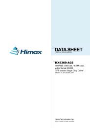
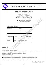
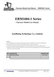
NEOTEC SEMICONDUCTOR LTD.<strong>NT7086</strong><strong>NT7086</strong>100 LQFP PACKAGE767778798081828384858687888990919293949596979899100<strong>NT7086</strong>504948474645444342414039383736353433323130292827261234567891011121314151617181920212223242575747372717069686766656463626160595857565554535251SC2SC1ELBCL1AMSCL2D1_SIDD2_DLD3_DMD4_DRVSSSHLVDDDISPOFFBMCSV0V12V43V5VEEERBSC80SC79SC78SC3SC4SC5SC6SC7SC8SC9SC10SC11SC12SC13SC14SC15SC16SC17SC18SC19SC20SC21SC22SC23SC24SC25SC26SC27SC77SC76SC75SC74SC73SC72SC71SC70SC69SC68SC67SC66SC65SC64SC63SC62SC61SC60SC59SC58SC57SC56SC55SC54SC53SC28SC29SC30SC31SC32SC33SC34SC35SC36SC37SC38SC39SC40SC41SC42SC43SC44SC45SC46SC47SC48SC49SC50SC51SC52PKG TYPEPKG THICKNESSPKG SIZEPAD PITCHPAD WIDTHPAD LENGTH= 100-LQFP= 1.40 (± 0.05) mm= 14.00 (± 0.10) X 14.00 (± 0.10) mm= 0.5 mm= 0.20 ( +0.07,-0.03) mm= 1.0 (+-0.1) mm12/04/2002 3/33
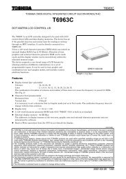
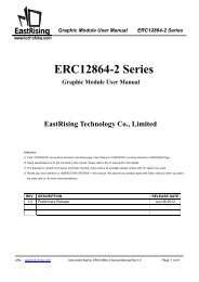
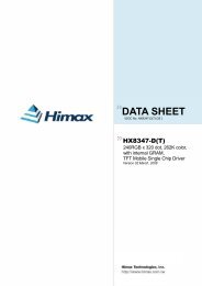
NEOTEC SEMICONDUCTOR LTD.<strong>NT7086</strong><strong>NT7086</strong>100 TQFP PACKAGE767778798081828384858687888990919293949596979899100<strong>NT7086</strong>504948474645444342414039383736353433323130292827261234567891011121314151617181920212223242575747372717069686766656463626160595857565554535251SC2SC1ELBCL1AMSCL2D1_SIDD2_DLD3_DMD4_DRVSSSHLVDDDISPOFFBMCSV0V12V43V5VEEERBSC80SC79SC78SC3SC4SC5SC6SC7SC8SC9SC10SC11SC12SC13SC14SC15SC16SC17SC18SC19SC20SC21SC22SC23SC24SC25SC26SC27SC77SC76SC75SC74SC73SC72SC71SC70SC69SC68SC67SC66SC65SC64SC63SC62SC61SC60SC59SC58SC57SC56SC55SC54SC53SC28SC29SC30SC31SC32SC33SC34SC35SC36SC37SC38SC39SC40SC41SC42SC43SC44SC45SC46SC47SC48SC49SC50SC51SC52PKG TYPEPKG THICKNESSPKG SIZEPAD PITCHPAD WIDTHPAD LENGTH= 100-TQFP= 1.00 (± 0.05) mm= 14.00 (± 0.10) X 14.00 (± 0.10) mm= 0.5 mm= 0.20 (± 0.03) mm= 1.0 (± 0.1) mm12/04/2002 4/33
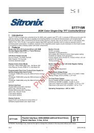
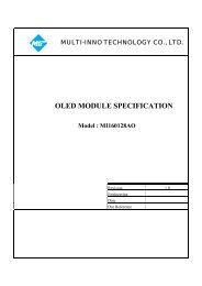
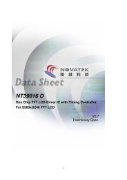
NEOTEC SEMICONDUCTOR LTD.<strong>NT7086</strong>PAD DIAGRAMNote: Please connects the substrate to V DD or Floating23SC52SC534 SC545 SC556 SC567 SC578 SC589 SC5910 SC6011 SC6112 SC6213 SC6314 SC6415 SC6516 SC6617 SC6718 SC6819 SC6920 SC7021 SC7122 SC7223 SC7324 SC7425 SC7526 SC7627 SC7728 SC7829 SC7930 SC801100999897969594939291SC51SC50SC49SC48SC47SC46SC45SC44SC43SC42SC41SC40SC39SC38SC37SC36SC35SC34SC33SC32SC31SC30ERB31VEE32V5V43V12V03334359089888786<strong>NT7086</strong>CHIP SIZE: 3340X3760 um 2PAD SIZE: 100X100 um 2MIN PITCH: 125 um36373839(0,0)CSMDISPOFFBVDDSHLVSSD4_DRD3_DMD2_DLD1_SIDCL2AMSCL1ELB4041424344854584468347824881498050SC29SC28SC27SC26SC25SC24SC23SC22SC21SC20SC19SC18SC17SC16SC15SC14SC13SC12SC11SC10SC9SC8SC7SC6SC5SC4SC3SC2SC1797877767574737271706968676665646362616059585756555453525112/04/2002 5/33
NEOTEC SEMICONDUCTOR LTD.<strong>NT7086</strong>PAD LOCATIONPad No. Pad name X Y Pad No. Pad name X Y1 SC51 -1313.50 1746.00 51 SC1 1542.00 -1754.002 SC52 -1544.00 1746.00 52 SC2 -1629.003 SC53 1621.00 53 SC3 -1504.004 SC54 1496.00 54 SC4 -1379.005 SC55 1371.00 55 SC5 -1254.006 SC56 1246.00 56 SC6 -1129.007 SC57 1121.00 57 SC7 -1004.008 SC58 996.00 58 SC8 -879.009 SC59 871.00 59 SC9 -754.0010 SC60 746.00 60 SC10 -629.0011 SC61 621.00 61 SC11 -504.0012 SC62 496.00 62 SC12 -379.0013 SC63 371.00 63 SC13 -254.0014 SC64 246.00 64 SC14 -129.0015 SC65 121.00 65 SC15 -4.0016 SC66 -4.00 66 SC16 121.0017 SC67 -129.00 67 SC17 246.0018 SC68 -254.00 68 SC18 371.0019 SC69 -379.00 69 SC19 496.0020 SC70 -504.00 70 SC20 621.0021 SC71 -629.00 71 SC21 746.0022 SC72 -754.00 72 SC22 871.0023 SC73 -879.00 73 SC23 996.0024 SC74 -1004.00 74 SC24 1121.0025 SC75 -1129.00 75 SC25 1246.0026 SC76 -1254.00 76 SC26 1371.0027 SC77 -1379.00 77 SC27 1496.0028 SC78 -1504.00 78 SC28 1621.0029 SC79 -1629.00 79 SC291746.0030 SC80-1754.00 80 SC30 1311.5031 ERB -1218.40 81 SC31 1186.5032 VEE -1048.70 82 SC32 1061.5033 V5 -923.70 83 SC33 936.5034 V43 -798.70 84 SC34 811.5035 V12 -673.70 85 SC35 686.5036 V0 -548.70 86 SC36 561.5037 CS -380.00 87 SC37 436.5038 M -255.00 88 SC38 311.5039 DISPOFFB -130.00 89 SC39 186.5040 VDD -5.00 90 SC40 61.5041 SHL 120.10 91 SC41 -63.5042 VSS 245.10 92 SC42 -188.5043 D4_DR 370.10 93 SC43 -313.5044 D3_DM 495.10 94 SC44 -438.5045 D2_DL 620.10 95 SC45 -563.5046 D1_SID 745.10 96 SC46 -688.5047 CL2 870.10 97 SC47 -813.5048 AMS 995.10 98 SC48 -938.5049 CL1 1120.10 99 SC49 -1063.5050 ELB 1245.10100 SC50 -1188.5012/04/2002 6/33
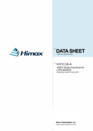
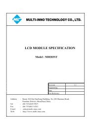
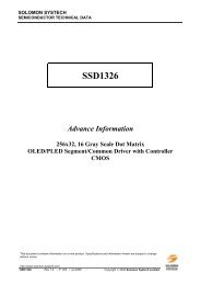
NEOTEC SEMICONDUCTOR LTD.<strong>NT7086</strong>BLOCK DIAGRAMSC1SC2SC3. . . . . .SC78SC79SC80V0V12V43V580-bit 4-level driver. . . . . . . . . . . . . .VEEMDISPOFFBOutputlevelselectorLCK80-bit level driver. . . . . . . . . . . . . .80 bit data latch /common data bidirectional shift registerD1_SIDD2_DLD3_DMD4_DR. . . . . . . . . . . . . .SCK20 X 4-bits segment databidirectional shift register/CL1CL2ClockcontrolData latch controlCSAMSPower downfunctionERBVDDVSSELB12/04/2002 7/33
NEOTEC SEMICONDUCTOR LTD.<strong>NT7086</strong>BLOCK DESCRIPTIONNAME FUNCTION COM / SEGClock controlGenerates latch clock (LCK), shift clock (SCK) and controlclock timing according to the input of CL1, CL2 and controlinputs (CS, AMS). In common driver application mode, this COM / SEGblock generates the shift clock (LCK) for the common dataBi-directional shift register.Determines the direction of segment data shift, and input data ofeach Data latch Bi-directional shift register. In 4-bit segment dataData latchparallel transfer mode, data is shifted by a 4-bit unit. In common SEGcontroldriver application mode, data is transferred to the common datashift register directly, which disables this block.Power downfunctionOutput levelselector20x4-bitsegment databi-directionalshift register80-bit datalatch /common databi-directionalshift register80-bit levelshifter80-bit 4-leveldriverControls the clock enable state of the current driver according tothe input value of enable pin (ELB or ERB). If enable input valueis “Low”, every clock of the current driver is enabled and theclock control block works. But if enable input is “High”, currentdriver is disabled and the input data value has no effect on theoutput level. So power consumption can be lowered.Controls the output voltage level according to the input controlpin (M and DISPOFFB) (refer to PIN DESCRIPTION).Stores output data value by shifting the input values. In 1-bitserial interface mode application, all 80 shift clocks (SCK) areneeded to store all the display data. But in 4-bit parallel transfermode application, only 20 clocks are needed. In common driverapplication mode, this block does not work.In segment driver application mode, the data from the 20x4-bitsegment data shift register are latched for segment driver output.In single-type common driver application, 1-bit input data (fromDL or DR pin) is shifted and latched by the direction accordingto the SHL signal input. In dual-type common application mode,80-bit registers are divided by two blocks and controlledIndependently (refer to NOTE 3).Voltage level shifter block for high voltage part. The inputs ofthis block are of logical voltage level and the outputs of thisblock are at high voltage level value. These values are input in tothe driver.Selects the output voltage level according to M and latched datavalue. If the data value is "High" the driver output is at selectedvoltage level (V0 or V5), and in the reverse case the driveroutput value is at the non-selected level (V12 or V43). Insegment driver application mode, non-selected output value isV2 or V3 and when in common driver application, this valuebecomes V1 or V4.SEGCOM / SEGSEGCOM / SEGSEGSEG12/04/2002 8/33
NEOTEC SEMICONDUCTOR LTD.<strong>NT7086</strong>PIN DESCRIPTIONPIN I/O NAME FUNCTION INTERFACELogical "High" input port (+5V±10%, +3V±VDDPower 10%)PowerVSSsupply 0V (GND)VEELogical "Low" for high voltage partLCD driver Bias supply voltage input to drive the LCD.V0,V12, output Bias voltage divided by the resistance isIPowerV43,V5 voltage usually used as a supply voltage source (referlevel to NOTE 2).SC1~SC80CL2MCL1OIIILCD driveroutputData shiftclockAC signalfor LCDdriveroutputData latchclockDisplay data output pin which corresponds tothe respective latch contents. One of V0, V12,V34 and V5 is selected as a display drivingvoltage source according to the combinationof the latched data level and M signal (refer toNOTE 1).Clock pulse input for the bi-directional shiftregister.– In segment driver application mode, thedata is shifted to 20 x4-bit segment data shift.The clock pulse, which was input when theenable bit (ELB/ERB) is in not activecondition, is invalid.– In common driver application mode, thedata is shifted to 80-bit common databi-directional shift register by the CL1 clock.Hence, this clock pin is not used (Open orconnect this pin to VDD).Alternate signal input pin for LCD driving. Normalframe inversion signal is input in to this pin.– In segment driver application mode, thissignal is used for latching the shift registercontents at the falling edge of this clock pulse.CL1 pulse "High" level initializespower-down function block.– In common driver application mode, CL1 isused as a shifting clock of common outputdata.LCDControllerControllerController12/04/2002 9/33
NEOTEC SEMICONDUCTOR LTD.<strong>NT7086</strong>PIN DESCRIPTION (CONTINUED)PIN I/O NAME FUNCTION INTERFACEControl input pin to fix the driver outputDISPOFFB I(SC1~SC80) to V0 level, during "Low" valueDisplayinput. LCD becomes non-selected by V0 levelOFF controloutput from every output of segment driversand every output of common drivers.ControllerCSICOM / SEGmodecontrolWhen CS = "Low", <strong>NT7086</strong> is used as an80-bit segment driver.When CS = "High", <strong>NT7086</strong> is set to an 80-bitcommon driverAccording to the input value of the AMS andthe CS pin, application mode of <strong>NT7086</strong> isdiffers as shown below.VDD/VSSAMSIApplicationmode selectCS AMS Application mode COM/SEG0 04-bit parallelinterface mode0 11-bit serial interfacemodeSEG1 0Single typeapplication Mode1 1Dual type applicationmodeCOMVDD/VSSD1_SID,D2_DL,D3_DM,D4_DRI/O-In segment driver mode, these pins are usedas 4-bit data input pin (when 4-bit parallelinterface mode AMS= ”low”), or D1_SID isused as serial data input pin and other pins arenot used (connect these to VDD) (when 1-bitDisplayserial interface mode AMS= ”high”).data input/-In common driver mode, the data is shiftedserial inputfrom D2_DL (D4_DR) to D4_DR (D2_DL),data/ left ,when in single interface moderight data(AMS= ”Low”). In dual-type application case,input outputthe data are shifted from D2_DL and D3_DM(D4_DR and D3_DM) to D4_DR(D2_DL). Ineach case the direction of the data shift and theconnection of data pins are determined bySHL input (refer to NOTE 3, NOT 4).Controller12/04/2002 10/33
NEOTEC SEMICONDUCTOR LTD.<strong>NT7086</strong>PIN DESCRIPTION (CONTINUED)PIN I/O NAME FUNCTION INTERFACESHL IWhen SHL = "Low", data is shifted from leftShiftto right.directionWhen SHL = "High", the direction is reversed.control(refer to NOTE3)-In segment driver mode, the internaloperation is enabled only when enable input(ELB or ERB) is "Low" (power downfunction). When several drivers a seriallyconnected, the enable state of each driver isshifted according to the SHL input. Connect VDD/VSSEnable data these pins as below.ELB, ERB I/O input/outputSegment driverSHLELB ERBL Output (open) Input (VSS)H Input (VSS) Output(open)-In common driver mode, the power downfunction is not used. Open these pins.NOTE 1. Output level control"X": don't careM Latched data DISPOFFBOutput level (CS1~CS80)SEG Mode COM ModeL L H V12(V2) V12(V1)L H H V0 V5H L H V43(V3) V43(V4)H H H V5 V0X X L V0 V012/04/2002 11/33
NEOTEC SEMICONDUCTOR LTD.<strong>NT7086</strong>(2) When CS = “High” (common driver application)AMS SHL ApplicationData DirectionmodeLSC1SC2SC3. . . . .. . . . .SC38SC39SC40SC41SC42Shift direction. . . . .SC43 . . . . .SC78SC79SC80Input pinD2_DLLHSingle-typeApplicationmode(COM)Input data(D2_DL)SC1SC2SC3. . . . .. . . . .SC38SC39SC40SC41SC42Shift direction. . . . .SC43 . . . . .Output data(D4_DR)SC78SC79SC80D4_DROutput data(D2_DL)Input data(D4_DR)Shift directionLSC1SC2SC3. . . . .. . . . .SC38SC39SC40SC41SC42. . . . .SC43 . . . . .SC78SC79SC80D2_DL,D3_DMHHDual-typeApplicationmode(COM)Input data 1(D2_DL)SC1SC2SC3. . . . .. . . . .SC38Input data 2(D3_DM)Shift directionSC39SC40SC41SC42. . . . .SC43 . . . . .Output data(D4_DR)SC78SC79SC80D4_DR,D3_DMOutput data(D2_DL)Input data 2(D3_DM)Input data 1(D4_DR)12/04/2002 14/33
NEOTEC SEMICONDUCTOR LTD.<strong>NT7086</strong>ELECTRICAL CHARACTERISTICSDC CHARACTERISTICS(1) Segment Driver ApplicationV(VSS = 0V, Ta = - 30 ~ +85°C)Characteristic Symbol Test Condition Min. Typ. Max. UnitOperating V DD - 2.7 - 5.5IH DD DDVoltage 1 V LCD V IN =V DD -V EE 6 - 28Input voltage V - 0.8V - V(1) V IL - 0 - 0.2V DDInput voltage V OH I CH =-0.4mA V DD -0.4 - -(2) V OL I OH =-0.4mA - - 0.4VInput leakagecurrent 1 (1)I IL1 V IN =V DD to V SS -10 - 10Input leakagecurrent 2 (3)I IL2 V IN =V DD to V EE -25 - 25μAOn resistance(4) R ON I ON =100μA - 2 4 kΩI STBY f CL1 =32kHZ, M=VSS V SS PIN - - 100 μASupplyV DD =5V - - 5Icurrent(5)DDf CL1 =32kHZ F M =80HZ V DD =3V - - 2mAI EEV DD =5V - - 500 μANOTES:1. Applied to CL1, CL2, ELB, ERB, D1_SID - D4_DR, SHL, DISPOFFB, M, CS, AMS pin2. ELB, ERB pin3. V0, V12, V43, V5 pin4. V LCD = V DD - V EE , V0 = V DD = 5V, V5= V EE = -23 VV12 = V DD -2/n(V LCD ), V43 = V EE +2/n(V LCD ), n = 17 (1/256 duty, 1/17 bias)5. V0 = V DD, V12 = 1.71V(V DD = 5V) or -0.06V (V DD = 3V),V43 = -19.71 V(VDD = 5V) or -19.94V (V DD = 3V), V5 = V EE = -23V, no-load condition (1/256 duty, 1/17 bias)4-bit parallel interface modeI STBY : V DD = 5V, f CL2 = 5.12MHz, SHL = V SS , DISPOFFB = V DD , M = V SS , display data pattern = 0000I DD : V DD = 3V, f CL2 = 4MHz, display data pattern = 0101V DD = 5 V, f CL2 = 5.12MHz, display data pattern = 0101I EE : V DD = 5V, f CL2 = 5.12MHz, display data pattern = 0101, V EE pin12/04/2002 16/33
NEOTEC SEMICONDUCTOR LTD.<strong>NT7086</strong>VDC CHARACTERISTICS (CONTINUED)(2) Common Driver Application(VSS = 0V, Ta = - 30 ~ +85°C)Characteristic Symbol Test Condition Min. Typ. Max. UnitOperating V DD - 2.7 - 5.5IH DD DDVoltage 1 V LCD V IN =V DD -V EE 6 - 28Input voltage V - 0.8V - V(1) V IL - 0 - 0.2V DDInput voltage V OH I CH =-0.4mA V DD -0.4 - -(3) V OL I OH =-0.4mA - - 0.4VInput leakagecurrent 1 (1)I IL1 V IN =V DD to V SS -10 - 10Input leakagecurrent 2 (2)I IL2 V IN =0V, V DD =5V(Pull up) -50 -125 -250μAInput leakagecurrent 3 (4)I IL3 V IN =V DD to V EE -25 - 25On resistance(5) R ON I ON =100μA - 2 4 kΩI STBY f CL1 =32kHZ, M=VSS V SS PIN - - 100SupplyV DD =5V - - 200Icurrent(6) DDf CL1 =32kHZ F M =80HZ V DD =3V - - 120μAV DD =5V - - 150I EENOTES:1. Applied to CL1, D2_DL (SHL = LOW), D4_DR (SHL = HIGH), SHL, DISPOFFB, M, CS, AMS pin2. Pull-up input pins : CL2, D1_SID, D3_DM (AMS = HIGH), ELB (SHL = LOW), ERB (SHL = HIGH)3. D2_DL (SHL = HIGH) , D4_DR (SHL = LOW) pin4. V0, V12, V43, V5 pin5. V LCD = V DD -V EE , V0 = V DD = 5V, V5 = V EE = -23VV12 = V DD -1/n(V LCD ), V43 = V EE +1/n(V LCD ), n = 17(1/256 duty, 1/17 bias)6. V0 = V DD , V12 = 3.35V (V DD = 5V) or 1.47V (V DD = 3V),V43 = -21.35V (V DD = 5 V) or -21.47V (V DD = 3 V), V5 = V EE = -23 V, no-load condition (1/256 duty, 1/17 bias)single-type mode operation : AMS = V SS , SHL = V SS , DISPOFFB = V DDD1_SID = D3_DM = VDD, D4_DR = OPEN, ELB = ERB = OPEN,I STBY : V DD = 5V, M = V SS , D2_DL = V SSI DD : f M = 80Hz, D2_DL = V DDV DD = 3 V, display data pattern = 10000000..., 01000000..., 00100000..., 00010000..., ..V DD = 5 V, display data pattern = 10000000..., 01000000..., 00100000..., 00010000..., ..I EE : f M = 80Hz, D2_DL = V DDV DD = 5V, current through V EE Pin, display data pattern = 10000000..., 01000000...,00100000..., 00010000...12/04/2002 17/33
NEOTEC SEMICONDUCTOR LTD.<strong>NT7086</strong>AC CHARACTERISTICS(1) Segment Driver Application(V SS = 0V, Ta = - 30 ~ +85°C)(1) VDD=5V±10% (2) VDD=3V±10%Characteristic Symbol Test condition UnitMin. Typ. Max. Min. Typ. Max.Clock cycle time t CY Duty=50% 125 - - 250 - -Clock pulse width t WCK - 45 - - 95 - -Clock rise/ fall time t R / t F - - - - - - 30Data set-up time t DS - 30 - 65 - -Data hold time t DH - 30 - 65 - -Clock set-up time t CS - 80 - 120 - - nsClock hold time t CH - 80 - 120 - -Propagation delay time t PHLELB output 60 125- -- -ERB output60125ELB,ERB set-up time t PSUELB input 30 65- -ERB input 3065- -DISPOFFB low pulsewidtht WDL - 1.2 - - 1.2 - - μsDISPOFFB clear time t CD - 100 - - 100 - - nsM – OUTpropagation delay timet PD1 - - 1.0 - - 1.2CL1 – OUTpropagation delay timet PD2 C L =15pF - - 1.0 - - 1.2 μsDISPOFFB – OUTpropagation delay timet PD3- - 1.0 - - -(2) Common Driver Application(V SS = 0V, Ta = - 30 ~ +85°C)(1) VDD=5V±10% (2) VDD=3V±10%Characteristic Symbol Test condition UnitMin. Typ. Max. Min. Typ. Max.Clock cycle time t CY Duty=50% 250 - - 500 - -Clock pulse width t WCK - 45 - - 95 - -Clock rise/ fall time t R / t F - - - 50 - - 50 nsData set-up time t DS - 30 - 65 - -Data hold time T DH - 30 - 65 - -DISPOFFB low pulsewidtht WDL - 1.2 - - 1.2 - - μsDISPOFFB clear time t CD - 100 - - 100 - -Output delay time t DL - - 200 - - 250nsM – OUTpropagation delay timet PD1 - - 1.0 - - 1.2CL1 – OUTpropagation delay timet PD2C L =15pF- - 1.0 - - 1.2 μsDISPOFFB – OUTpropagation delay timet PD3- - 1.0 - - 1.212/04/2002 18/33
NEOTEC SEMICONDUCTOR LTD.<strong>NT7086</strong>(3) Segment Driver Application TimingCL10.8VDD0.2VDDt WCKt CS0.8VDD0.2VDDt CHCL20.8VDD0.2VDD0.8VDDt WCKt WCK0.2VDD0.8VDD0.2VDDt Rt Ft CYt DSt DHD1_SID - D4_DR0.8VDD0.2VDDDISPOFFBtWDLt CDCL1CL2ELB, ERB(Output 1)ELB, ERB(Input 2)1 2 3 19 200.2VDDt PHL0.2VDDt PSU0.2VDD0.8VDDM0.8VDD0.2VDDt PD1CL10.2VDDt PD2DISPOFFBSC1 - SC80(Latched data)0.8VDD0.2VDDt PD312/04/2002 19/33
NEOTEC SEMICONDUCTOR LTD.<strong>NT7086</strong>(4) Common Driver Application TimingCL10.8VDD0.8VDDt DWCKHt Rt F0.2VDDt CY0.2VDDt Ft DSt DH(*1) DI0.8VDD0.2VDD0.8VDD0.2VDDt DL(*1) DODISPOFFBt WDLt CD0.8VDD0.2VDD(*1) When in single-type interface modeDI=>DDL(SHL=L), D4_DR(SHL=H)DO=>D4_DR(SHL=L), D2_DL(SHL=H)When in dual-type interface modeDI=>D2_DL and D3_DM(SHL=L),D4_DR and D3_DM(SHL=H)DO=>D4_DR(SHL=L), D2_DL(SHL=H)M0.8VDD0.2VDDt PD1CL1DISPOFFBSC1 - SC80(Latched data)0.2VDDt PD20.8VDD0.2VDDt PD312/04/2002 20/33
NEOTEC SEMICONDUCTOR LTD.<strong>NT7086</strong>POWER DOWN FUNCTIONIn the case of cascade connection of segment mode drivers, <strong>NT7086</strong> has a "power downfunction" In order to reduce the power consumption.SHL Enable input Enable output Current driver status The other drivers statusL ERB ELBWhile ERB ="Low",current driver is enabled.DisabledH ELB ERBWhile ELB ="Low",current driver is enabled.Disabled* In the case of common driver application, power down function does not work.CL1CL2ELB1(input1)1 2 n-1 n 1 2 n-1 n 1 2 n-1 n 1 2 n-1 n 1 2 n-1ERB1/ELB2(Output1/Input2)ERB2/ELB3(Output2/Input3)ERB3/ELB4(Output3/Input4)ELB4(Output)NOTES:1. SHL = High (ELB = Input, ERB = Output)2. When in 4-bit parallel interface mode: n = 20When in 1-bit serial interface mode: n = 8012/04/2002 21/33
NEOTEC SEMICONDUCTOR LTD.<strong>NT7086</strong>OPERATION TIMING DIAGRAM(1) 4-bit parallel mode interface segment driverWhen SHL= ”Low”CL219 20 1 2 3 19 20 1 2D1_SID SC5 SC1 SC77 SC73 SC69 SC5 SC1 SC77 SC73D2_DL SC6 SC2 SC78 SC74 SC70 SC6 SC2 SC78 SC74D3_DM SC7 SC3 SC79 SC75 SC71 SC7 SC3 SC79 SC75D4_DR SC8 SC4 SC80 SC76 SC72 SC8 SC4 SC80 SC76ERB(Input)ELB(Onput)CL1SC1 - SC80When SHL= ”High”CL219 20 1 2 3 19 20 1 2D1_SID SC76 SC80 SC4 SC8 SC12 SC76 SC80 SC4 SC8D2_DL SC75 SC79 SC3 SC7 SC11 SC75 SC79 SC3 SC7D3_DM SC74 SC78 SC2 SC6 SC10 SC74 SC78 SC2 SC6D4_DR SC73 SC77 SC1 SC5 SC9 SC73 SC77 SC1 SC5ELB(Input)ERB(Onput)CL1SC1 - SC8012/04/2002 22/33
NEOTEC SEMICONDUCTOR LTD.<strong>NT7086</strong>(2) 1-bit serial mode interface segment driverWhen SHL= ”Low”CL279 80 1 2 3 79 80 1 2D1_SID SC2 SC1 SC80 SC79 SC78 SC2 SC1 SC80 SC79ERB(Input)ELB(Onput)CL1SC1 - SC80When SHL= “High”CL279 80 1 2 3 79 80 1 2D1_SID SC79 SC80 SC1 SC2 SC3 SC79 SC80 SC1 SC2ELB(Input)ERB(Onput)CL1SC1 - SC8012/04/2002 23/33
NEOTEC SEMICONDUCTOR LTD.<strong>NT7086</strong>(3) Single type interface mode common driverWhen SHL= “Low”CL1D2_DLD4_DRCOM_DATA1COM_DATA2COM_DATA3COM_DATA79COM_DATA8079 80 1 2 79 80 1 2Current Driver's COMMON areaWhen SHL= ”High”CL1D4_DRD2_DLCOM_DATA1COM_DATA2COM_DATA3COM_DATA79COM_DATA8079 80 1 2 79 80 1 2Current Driver's COMMON area12/04/2002 24/33
NEOTEC SEMICONDUCTOR LTD.<strong>NT7086</strong>(4) Dual-type interface mode common driverWhen SHL= “Low”CL11 2 3 39 40 1 2 3 39 40D2_DLD3_DMD4_DRCOM_DATA1COM_DATA2COM_DATA3COM_DATA39COM_DATA40COM_DATA41COM_DATA42COM_DATA43COM_DATA79COM_DATA80When SHL= “High”CL11 2 3 39 40 1 2 3 39 40D2_DLD3_DMD4_DRCOM_DATA1COM_DATA2COM_DATA3COM_DATA39COM_DATA40COM_DATA41COM_DATA42COM_DATA43COM_DATA79COM_DATA8012/04/2002 25/33
NEOTEC SEMICONDUCTOR LTD.<strong>NT7086</strong>(5) Common / Segment driver timing (1/200 duty)CL1199 200 1 200 1 199 200 1 199 200Latched data (SEG)MCOM_DATA1COM_DATA199COM_DATA200V0V1COM1V4V5COM199COM200V0V1V4V5V0V1V4V5SEG_DATA1SEG1V0V1V2V3V4V5CL21 2 18 19 20 1CL1D1 - D4Latched dataMEnable Out12/04/2002 26/33
NEOTEC SEMICONDUCTOR LTD.<strong>NT7086</strong>APPLICATION INFORMATION1-bit serial interface mode (80 Ch. Segment mode)a) Lower view (SHL= L, AMS= H)LCD PANELS1S80S81S160SnSn+801-bit serialdata inputSC80SC1ERBELBCS <strong>NT7086</strong>AMSD2_DL -SHLD1_SID D4_DRSC80ERBCSAMSSHL<strong>NT7086</strong>D1_SIDSC1ELBD2_DL -D4_DRSC80ERBSC1ELBCS <strong>NT7086</strong>AMSD2_DL -SHLD1_SID D4_DRb) Upper view (SHL= H, AMS= H)1-bit serialdata inputD2_DL -D4_DRELBSC1D1_SIDSHLAMSCS<strong>NT7086</strong>ERBSC80D2_DL -D4_DRELBSC1D1_SIDSHLAMSCSERBSC80<strong>NT7086</strong>D2_DL -D4_DRELBSC1D1_SIDSHLAMSCSERBSC80<strong>NT7086</strong>S1 S80 S81 S160 Sn Sn+80LCD PANEL12/04/2002 27/33
NEOTEC SEMICONDUCTOR LTD.<strong>NT7086</strong>4-bit parallel interface mode (80 Ch. Segment driver)a) Lower view (SHL= L, AMS = L)LCD PANELS1S80S81S160SnSn+80SC80SC1ERBELBCS <strong>NT7086</strong>AMSSHLD1_SID - D4_DRSC80SC1ERBELBCS <strong>NT7086</strong>AMSSHLD1_SID - D4_DRSC80SC1ERBELBCS <strong>NT7086</strong>AMSSHLD1_SID - D4_DR4-bit serialdata input444b) Upper view (SHL= H, AMS = L)4-bit serialdata inputD1_SID - D4_DRSHLAMS<strong>NT7086</strong> CSELBSC14ERBSC80D1_SID - D4_DRSHLAMS<strong>NT7086</strong> CSELBSC14ERBSC80D1_SID - D4_DRSHLAMS<strong>NT7086</strong> CSELBSC14ERBSC80S1 S80 S81 S160 Sn Sn+80LCD PANEL12/04/2002 28/33
NEOTEC SEMICONDUCTOR LTD.<strong>NT7086</strong>Single type interface mode (80 Ch. Common driver)input data 1D4_DRSC80C1CSAMSSHL<strong>NT7086</strong>D2_DLSC1C80D4_DRSC80C81CSAMSSHL<strong>NT7086</strong>D2_DLSC1C160LCD PANELD4_DRSC80C161CSAMSSHL<strong>NT7086</strong>D2_DLSC1C24012/04/2002 29/33
NEOTEC SEMICONDUCTOR LTD.<strong>NT7086</strong>Dual-type interface mode (40 Ch. + 40Ch. Common driver)input data 1D4_DRSC80C1CSAMSSHL<strong>NT7086</strong>D2_DLSC1C80D4_DRSC80C81LCD PANEL (1/2)CSAMSSHL<strong>NT7086</strong>D2_DLSC1C160inputdata 2D3_DM D4_DRSC80C161CSAMSSHL<strong>NT7086</strong>D2_DLSC40SC41SC1C200C201C240D4_DRSC80C241CSAMSSHL<strong>NT7086</strong>D2_DLSC1C320LCD PANEL (2/2)D4_DRSC80C321CSAMSSHL<strong>NT7086</strong>D2_DLSC1C400NOTE: Using this application mode (dual-type common mode), the duty ratio can be reduced to half. In case, 1/200duty can be used to driver the 400 common LCD panel.12/04/2002 30/33
NEOTEC SEMICONDUCTOR LTD.<strong>NT7086</strong>APPLICATION CIRCUIT EXAMPLEVDDRR(n-4)RRRV0COM/SEGV1COMV2V3V4COMV5SEGSEGCOM/SEG4 4V0-V5 D1_SID - D4_DRDISPOFFBMELB <strong>NT7086</strong>AMSCSSHLCL1CL2ERBSC1 . . . . . . . . . . . SC804 4V0-V5 D1_SID - D4_DRDISPOFFBMELB <strong>NT7086</strong>AMSCSSHLCL1CL2ERBSC1 . . . . . . . . . . . SC804 4V0-V5 D1_SID - D4_DRDISPOFFBMELB <strong>NT7086</strong>AMSCSSHLCL1CL2ERBSC1 . . . . . . . . . . . SC80S1 S80 S81 S160 S161 S240VSSVEE4MDISPOFFBCSAMSSHLV0-V5<strong>NT7086</strong>CL1D4_DRSC80SC1D2_DLC1C804MDISPOFFBCSAMSSHLV0-V5<strong>NT7086</strong>CL1D4_DRSC80SC1D2_DLC81C160240 X 240 LCD MODULEControllerDISPOFFBFRAME(M)COM_DATAD1-D4CL1CL24MDISPOFFBCSAMSSHLV0-V5<strong>NT7086</strong>CL1D4_DRSC80SC1D2_DLC161C24012/04/2002 31/33
NEOTEC SEMICONDUCTOR LTD.<strong>NT7086</strong>PRECAUTIONSPrecautions when connecting or disconnecting the power supplyThis IC has a high-voltage LCD driver, so it may be permanently damaged by a high currentwhich may flow if voltage is supplied to the LCD drive power supply while the logic systempower supply is floating. The details are as follows.When connecting the power supply, connect the LCD drive power after connecting thelogic system power. Furthermore, when disconnecting the power, disconnect the logicsystem power after disconnecting the LCD drive power.And when connecting the logic power supply, the logic condition of this IC inside is insecure.Therefore connect the LCD drive power supply after resetting logic condition of this IC inside on/DISPOFF function. After that, cancel the /DISPOFF function after the LCD drive power supplyhas become stable. Furthermore, when disconnecting the power, set the LCD drive output pins tolevel V5 on /DISPOFF function. Then, disconnect the logic system power after disconnecting theLCD drive power.When connecting the power supply, follow the recommended sequence shown here.VDD/DISPOFFVEEVDDVSSVDDVSSVSSVEE12/04/2002 32/33
NEOTEC SEMICONDUCTOR LTD.<strong>NT7086</strong>VERSION HISTORY:DateDescription6/5/2002 1. Add the notice of substrate connection.7/24/2002 1. Add the LQFP PKG description.1. Add precautions of power supply.12/04/20022. Add order number ( page 2 )3. Add TQFP package12/04/2002 33/33