FORMIKE ELECTRONIC CO.,LTD
FORMIKE ELECTRONIC CO.,LTD
FORMIKE ELECTRONIC CO.,LTD

Create successful ePaper yourself
Turn your PDF publications into a flip-book with our unique Google optimized e-Paper software.
<strong>FORMIKE</strong> <strong>ELECTRONIC</strong> <strong>CO</strong>.,<strong>LTD</strong>PRDUCT SPECIFICATONTFT LCD MODULEMODEL : KWH028Q06-F02【 】 Preliminary Specification【 ◆ 】 Finally SpecificationCUSTOMER'S APPROVALSIGNATURE:DATE:APPROVED PM PD PREPAREDBY REVIEWD REVIEWD BYWayne Li tong Zhengjinrong JullyPrepared By :<strong>FORMIKE</strong> <strong>ELECTRONIC</strong> <strong>CO</strong>.,<strong>LTD</strong>Address : A909, Huaying Building, 97 Nanshang Road,Nanshan District, Shenzhen, China.518054TEL:(86) 755 88306921,88306931 FAX:(86) 755 88304615Http:// www.wandisplay.com● This specification is subject to change withouth notice.Please contact <strong>FORMIKE</strong> or it'srepresentative before designing your product based on this specification.Issued Date: June-28-20091
Formike Electronic Co.,Ltd.Model No.:KWH028Q06-F02Document Revision HistoryVersin Data Page Description Changed BYA0 Jun-26-2009-- First issue Stephen2
ContentsFormike Electronic Co.,Ltd.Model No.:KWH028Q06-F02Page1. LCM Specification……………………………………………..….42. Functional Block Diagram…………………………………..…….53. Mechanical Specification…………………………………….……64. Electrical Units……………………………………………….……75. AC Characteristics…………………………………...…….….…..116. Optical Specifications……………………………………….…….147. Reliability Test Items………………………………………….…..168. Package(TBD)…………………………………………….……….179. Handling Precautions…………………………………………..….173
Formike Electronic Co.,Ltd.Model No.:KWH028Q06-F021. LCM Specification1.1 DescriptionKWH028Q06-F02 is a transmissive type color active matrix liquid crystal display (LCD)which uses amorphous thin film transistor (TFT) as switching devices. This product iscomposed of a TFT LCD panel, a drive IC, a FPC, and a WLED-backlight unit. The activedisplay area is 2.8 inches diagonally measured and the native resolution is 240*RGB*320.Features of this product are listed in the following table.1.2 Functions & FeaturesTable1.1 Module Functions & FeaturesParameter Value UnitLCD Mode a-Si TFT/transmissive -Color 262K -Display Resolution 240*RGB*320 pixelsOUTLINE DIMEMSIONS 50.00(W) x69.20(H) x3.70(T) mmActive Area(A.A) 43.20 (W) x 57.60(H) mmPixel Arrangement RGB-stripe -Viewing Direction12 O’clockDisplay ModeNormally whiteLCD Controller/Driver ILI9328 or compatible -IC Package Type <strong>CO</strong>G -MPU interface Standard 8080 system 8 /16 -bit paraller -Power Supply Voltage 2.5~3.3 VBack-light White LED*4 pcsPixel Arrangment4
Formike Electronic Co.,Ltd.Model No.:KWH028Q06-F022. Functional Block Diagram5
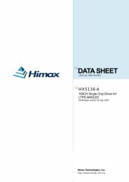
AK4K3K2K1K1K2K3K4A1Formike Electronic Co.,Ltd.Model No.:KWH028Q06-F023. Mechanical Specificatin8. GENERAL TOLERANCE: ±0.27. DRIVER IC: ILI93256. STORAGE TEMP: -30°C~ +80°C5. OPERATING TEMP: -20°C~ +70°C4. BL INPUT CURRENT: 60mA3. BACKLIGHT: 4 CHIP-WHITE LED2. VIEWING DIRECTION: 12 O'CLOCK1. DISPLAY TYPE: 2.8’TFT,TRANSMISSIVENOTES:A7,0041,0039,00P1.0*(37-1)=36,00(W=0.5)4,001 37DOUBLE SIDE TAPE(T=0.5)(29,50)P0.8*4=3,200,50+X+Y-X-YA K K K KY+dot size 0.18(H)x0.18(V)mm69,2068,50 TP 0,3067,00 LCD61,95 TP A,AX-X+Y-1,0363,29 TP V,A 1,9557,60 LCD A,A2.8" TFT 262K240 X RGB X 320View direction(12 O'clock)2,703,0812,0043,20 LCD A,A44,40 TP A,A45,51 TP V,A48,60 LCD49,60 TPA50,004,0011,003,402,802,190,700,20K1K2K3K4Vf=3.2V(TPYE)BACKLIGHT CIRCUIT2,85±0.103,7±0.20A-A4-0,80Custumer Ref. Model No. KWH028Q02-F05 Drawing Title KWH028Q06-F02---UnmarkedApprove KamPart No.MaterialUnitToleranceScale Page---Checked Stephen±0.2 mm 1:1 ofDrawing No.--- DrawLilyDate 2009-062-26 Rev ---A<strong>FORMIKE</strong> <strong>ELECTRONIC</strong> <strong>CO</strong>.,<strong>LTD</strong>3637DB7DB835DB637 13334GNDFPC 弯 折 后 示 意 图32VCCVCC31RESET30DB17焊 锡 高 度 不 高 于 0.3mm2928DB15DB16<strong>CO</strong>MPONENT AREA1,20252627DB14<strong>CO</strong>MPONENT AREADB12DB13A K K K K24DB1127,61±0.523DB1022DB521NC20LEDK13719LEDK218LEDK368,25±0.117LEDK416LEDA15Y-14X-13Y+12X+11IM04-?0,90±0.1010RD9WR0,508RS7CS6VCC48,80±0.10,605GND4DB43DB32DB21DB1Reversion Dispcription Date Signed6
Formike Electronic Co.,Ltd.Model No.:KWH028Q06-F024. Electrical Units4.1 Electrical Specification4.1.1 Absolute Maximum RatingsThe absolute maximum ratings are list on Table 4.1. When used out of the absolute maximumratings, the LCM may be permanently damaged. Using the LCM within the following electricalcharacteristics limit is strongly recommended for normal operation. If these electricalcharacteristic conditions are exceeded during normal operation, the LCM will malfunction andcause poor reliability.Table 4.1 Module Absolute Maximun RatingsItem Symbol Unit Value NotePower supplyVoltage(1)Vcc V -0.3~4.0Power supplyVoltage(2)Vci~VSS V 2.5~3.3Power supplyVoltage(3)VGH~Vss V 10~20Power supplyVoltage(4)VSS~VGH V 10~20 -Inout Voltage Vi V -0.3 to Vcc+0.3OperatingTemperatureTop ℃ -20 to +70StorageTemperatureTst ℃ -30 to +80(VSS=0V)4.2 Pin Descriptions4.2.1 TFT LCD Panle interface FPC Pin Descripton7
Formike Electronic Co.,Ltd.Model No.:KWH028Q06-F02No. Symbol Functional Remark1 DB1 Data bus2 DB2 Data bus3 DB3 Data bus4 DB4 Data bus5 GND Ground6 VCC Power7 CS Chip select pin of serial inter face8 RS Data or command9 WR Write signal10 RD Read signal11 IMO Interface mode select ; IM0=0 16bit ; IM0=1 8bit12 X+ Touch panel X+13 Y+ Touch panel Y+14 X- Touch panel X-15 Y- Touch panel Y-16 LED-A LED A17 LED-K4 LED K418 LED-K3 LED K319 LED-K2 LED K220 LED-K1 LED K121 NC No connection22 DB5 Data bus23 DB10 Data bus24 DB11 Data bus25 DB12 Data bus26 DB13 Data bus27 DB14 Data bus28 DB15 Data bus29 DB16 Data bus30 DB17 Data bus31 REST Reset din32 VCC Power33 VCC Power34 GND Ground35 DB6 Data bus36 DB7 Data bus37 DB8 Data bus8
Formike Electronic Co.,Ltd.Model No.:KWH028Q06-F024.3 Electrical characteristics (Ta=25℃)4.3.1 DC characteristics(VCC = 2.40 ~ 3.30V, IOVCC = 1.65 ~ 3.30V, Ta= -40 ~ 85 °C)Item Symbol Unit Test Condition Min. Typ. Max. NoteInput high voltage V IH V VCC= 1.8 ~ 3.3V 0.8*IOVCC - IOVCC -Input low voltage V IL V VCC= 1.8 ~ 3.3V -0.3 - 0.2*IOVCC -Output high voltage(1)( DB0-17 Pins)Output low voltage( DB0-17 Pins)V OH1 V IOH = -0.1 mA 0.8*IOVCC - - -V OL1VIOVCC=1.65~3.3VVCC= 2.4 ~ 3.3V IOL = 0.1mA- - 0.2*IOVCC -I/O leakage current I LI µA Vin = 0 ~ VCC -0.1 - 0.1 -Current consumptionduring normal operation(V CC – DGND )Current consumptionduring standby mode(V CC – DGND )LCD Drive Power SupplyCurrent( DDVDH-DGND )LCD Driving Voltage( DDVDH-DGND )I OP µAVCC=2.8V , Ta=25°C , fOSC = 512KHz( Line) GRAM data = 0000h-100(VCC)- -I ST µA VCC=2.8V , Ta=25 °C - 5 10 -ILCDmAVCC=2.8V , VREG1OUT =4.8VDDVDH=5.0V , fOSC = 512KHz (320line) , Ta=25 °C, GRAM data = 0000h,REV=”0”, SAP=”001”, ON4-0=”0”,OP4-0=”0”, MP52-00=”0”,MN52-00=”0”, CP12-00=”0”CN12-00=”0- 3.0 - -DDVDH V - 4.5 - 6 -Output voltage deviation mV - - 10 - -Dispersion of the AverageOutput VoltageV mV - -10 - 10 -9
Formike Electronic Co.,Ltd.Model No.:KWH028Q06-F024.4 Back-light SpecificationTable 4.3 Back-light SpecificationItem Symbol Min. Typ. Max. Unit RemarkSupply Voltage VBAT - 3.2 3.4 V NoteFormard current If - 15 - mAPowerConsumptionNote:PBL- 180 - mW NoteTable 4.4 Back-light SpecificationItem Symbol Conditions Min. Typ. Max. UnitSupply Voltage VF Only3.0 3.2 3.4 VSupply CurrentIF Backlight 15x4=60 mABacklightAverage BrightnessIV Current(With LCD dots all on)IF=15mA- 2800 - Cd/m2CIE Color Coordinate(Without LCD)UniformityColorX Backlight 0.24 - 0.29Current-Y IF=15mA 0.24 - 0.29BacklightB Current 80 - - (%)IF=15mAWhite10
Formike Electronic Co.,Ltd.Model No.:KWH028Q06-F025. AC Characterustics5.1.1 Clock CharcteristicsItem Symbol Unit Min. Typ. Max.External clock frequency Fcp KHz T.B.D 335 T.B.DExternal clock duty ratio Duty % 45 50 55External clock rise time Trcp s - - 0.2External clock fall time Tfcp s - - 0.2R-C oscillation clock fOSC KHz 275 335 395Table 5.1:Clock Charcteristics (Vcc=2.4~3.3V)TestConditionVcc=2.4~3.3VVcc=2.4~3.3VVcc=2.4~3.3VVcc=2.4~3.3VRf=130KΩ,Vcc=2.8V5.1.2 8080 System(16bits)Bus Interface Timing CharacteristicsItem System Unit Min. Typ. Max.TestConditionBus cycle timeWrite tCYCW ns 300 - - Figure5.1Read tCYCW ns 500 - - Figure5.1Write low-level pulse width PWLW ns 40 - - Figure5.1Read low-level pulse width PWLR ns 250 - - Figure5.1Write high-level pulse width PWHW ns 30 - - Figure5.1Read high-level pulse width PWHR ns 200 - - Figure5.1Write / Read rise / fall timeTWRr,TwRfns - - 25 Figure5.1Setup Write(RS to NCS,E_NWR) tAS ns 5 - - Figure5.1time Read(RS to NCS,RW_NRD) tAS 5 - - Figure5.1Address hold time tAH ns 5 - - Figure5.1Write data setup time tDSW ns 15 - - Figure5.1Write data hold time tH ns 15 - - Figure5.1Read data delay time tDDR ns - - 80 Figure5.1Read data hold time tDHR ns 5 - - Figure5.111
Formike Electronic Co.,Ltd.Model No.:KWH028Q06-F02Table 5.2:Normal Write Mode(HWM=0)/(Vcc=2.4~3.3V)TestItem System Unit Min. Typ. Max.ConditionBus cycle timeWrite tCYCW ns 100 - - Figure5.1Read tCYCW ns 500 - - Figure5.1Write low-level pulse width PWLW ns 40 - - Figure5.1Read low-level pulse width PWLR ns 250 - - Figure5.1Write high-level pulse width PWHW ns 30 - - Figure5.1Read high-level pulse width PWHR ns 200 - - Figure5.1Write Read/ rise/fall timeWRr,tWRFns - - 25 Figure5.1Setup Write(RS to NCS,E_NWR) ns 5 - - Figure5.1tAStime Read(RS to NCS,RW_NRD)ns 5 - - Figure5.1Address hold time tAH ns 5 - - Figure5.1Write data setup time tDSW ns 15 - - Figure5.1Write data hold time tH ns 20 - - Figure5.1Read data delay time tDDR ns - - 200 Figure5.1Read data hold time tDHR ns 5 - - Figure5.1Table 5.3 High-Speed Write Mode (HWM=1)/(Vcc=2.4~3.3V)5.1.3 80-system(8Bits) Bus Interface Timing CharacteristicsItem Symbol Unit Min. Typ. Max.TestConditionBus cycle timeWrite tCYCW ns 300 - - Figure5.1Read tCYCW ns 500 - - Figure5.1Write low-level pulse width PWLW ns 40 - - Figure5.1Read low-level pulse width PWLR ns 250 - - Figure5.1Write high-level pulse width PWHW ns 30 - Figure5.1Read high-level pulse width PWHR ns 200 - Figure5.1Write Read/ rise/fall timeWRr,tWRFns - - 25 Figure5.1Setup Write(RS to NCS,E_NWR) ns 5 - - Figure5.1tAStime Read(RS to NCS,RW_NRD)ns 5 - - Figure5.1Address hold time tAH ns 5 - - Figure5.1Write data setup time tDSW ns 15 - - Figure5.1Write data hold time tH ns 20 - - Figure5.1Read data delay time tDDR ns - - 120 Figure5.1Read data hold time tDHR ns 5 - - Figure5.112
Formike Electronic Co.,Ltd.Model No.:KWH028Q06-F02Table 5.4 Normal Write Mode(HWM=0)/(Vcc=2.4~3.3V)5.2 Timing Characteristic5.2.1 8080 System Bus Operation13
Formike Electronic Co.,Ltd.Model No.:KWH028Q06-F026. Optical SpecificationsFigure 5.1:8080 System Bus TimingNOTE (1)Definition of Contrast Ratio(CR):The contrast ratio can be calculated by the following expression. Contrast Ratio (CR) =L63 / L0L63: Luminance of gray level 63L0: Luminance of gray level 0CR = CR (10)CR (X) is corresponding to the Contrast Ratio of the point X at Figure in Note (6).14
Formike Electronic Co.,Ltd.Note (2) Definition of Response Time (TR, TF):Model No.:KWH028Q06-F02Note (3) Definition of viewing Angle:*** The above “Viewing Angle” is the measuring position with Largest Contrast Ratio; not forgood image quality.View Direction for good image quality is 6 O’clock. Module maker can increase the “ViewingAngle” by applyingWide View Film.15
Formike Electronic Co.,Ltd.Model No.:KWH028Q06-F02Note (4) Measurement Set-Up:The LCD module should be stabilized at a given temperature for 20 minutes to avoidabrupt temperature changeduring measuring. In order to stabilize the luminance, the measurement should be executedafter lighting Backlight for20 minutes in a windless room.Note(5)16
Formike Electronic Co.,Ltd.Model No.:KWH028Q06-F027. Reliability Test ItemsReliability Test Criteria:Display function should be no change under normal operating condition.8. Package(TBD)9. Handling Precautions9.1 SafetyThe liquid crystal in the LCD is poisonous. Keep away from your mouth and eyes. If the liquidcrystal contacts with your skin, mouse or clothes, use soap to wash it off immediately.9.2 Handlingi. The LCD panel is made by thin glass. Prevent the panel from mechanical shock or puttingexcessive force on its surface.ii. The polarizer attached on the display is very easy to be damaged, handle it with specialattention.iii. To avoid contamination on the display surface, do not touch the display surface with barehands.iv. The transparent electrodes may be disconnected if you use the LCD panel under17
dew-condensing environment.v. The characteristics of the semiconductor devices may be affected when they are exposed tolight, possibly resulting in malfunctioning of the ICs. To prevent such malfunctioning of theICs, make sure the application and the mounting of the panel are designed so that the IC is notexposed to light.9.3 Static ElectricityGround soldering iron tips, tools and testers when you operate. Also ground your body whenhandling the products and store the products in an anti-electrostatic container.9.4 StorageStore the products in a dark place where the temperature is within the range of 25±10 and withlow humidity (65%RH or less). Do not store the LCD product in an atmosphere containingorganic solvents or corrosive gases.9.5 CleaningFormike Electronic Co.,Ltd.Model No.:KWH028Q06-F02Do not wipe the polarizer with dry cloth, as it might cause scratching. Wipe the polarizer with asoft cloth soaked with petroleum IPA. Other chemical might damage the panel.18