BIM Essential Guide â For Architectural Consultants - Corenet
BIM Essential Guide â For Architectural Consultants - Corenet
BIM Essential Guide â For Architectural Consultants - Corenet

You also want an ePaper? Increase the reach of your titles
YUMPU automatically turns print PDFs into web optimized ePapers that Google loves.
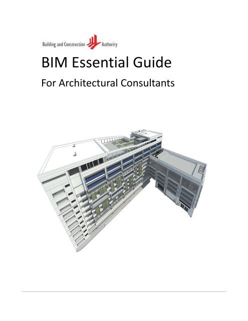
<strong>BIM</strong> <strong>Essential</strong> <strong>Guide</strong><strong>For</strong> <strong>Architectural</strong> <strong>Consultants</strong>
BCA acknowledges the leadership provided bythe <strong>BIM</strong> Steering Committee in support of theproduction of the <strong>BIM</strong> <strong>Essential</strong> <strong>Guide</strong>sThe <strong>BIM</strong> <strong>Essential</strong> <strong>Guide</strong>s have been drafted bythe Centre for Construction IT on behalf of BCAand the <strong>BIM</strong> Steering Committee.©Building and Construction Authority 2013Building and Construction Authority5 Maxwell Road#16-00 Tower Block MND ComplexSingapore 059110www.bca.gov.sgFirst published August 2013While every effort has been made to ensure theaccuracy and quality of information containedin this publication, the Building andConstruction Authority, its employees, agentsor industry partners can take no responsibilityfor the subsequent use of this information, norfor any errors or omissions that it may contain.Cover image and design courtesy of RSPArchitects Planners & Engineers (Pte) Ltd andthe BCA Academy of the Built Environment.
<strong>BIM</strong> <strong>Essential</strong> <strong>Guide</strong> – <strong>For</strong> <strong>Architectural</strong> <strong>Consultants</strong>ContentsCEO’s Message ___________________________________________________________________ iiACKNOWLEDGEMENTS ____________________________________________________________ iiiOBJECTIVES _____________________________________________________________________ 1Suggested <strong>BIM</strong> Deliverables ________________________________________________________ 2Preparation & Conceptual Design ____________________________________________________ 3Understanding Client’s Requirements _________________________________________ 4Site Model based on Surveyor's / Civil Engineer's Data ___________________________ 6Conceptual Massing _______________________________________________________ 9Schematic Design ________________________________________________________________ 13Schematic Model ________________________________________________________ 14Collaboration with Developers (Design Only) __________________________________ 16Collaboration with Structural Engineers ______________________________________ 17Detailed Design _________________________________________________________________ 19Detailed Design Model ____________________________________________________ 20Collaboration with Mechanical, Electrical & Plumbing Engineers __________________ 23Collaboration with Specialist <strong>Consultants</strong> and Fabricators ________________________ 26Tender Documentation ____________________________________________________ 28Construction ___________________________________________________________________ 30Others ________________________________________________________________________ 31Value- Added Services ____________________________________________________ 31Regulatory Submissions ___________________________________________________ 31Model version control _____________________________________________________ 32i
<strong>BIM</strong> <strong>Essential</strong> <strong>Guide</strong> – <strong>For</strong> <strong>Architectural</strong> <strong>Consultants</strong>CEO’s MessageDear readers,Building Information Modelling (<strong>BIM</strong>) has gained much traction in recentyears as digital construction technology that will fundamentally transformthe building and construction industry practice in the delivery of anexcellent built environment. It is a game changing technology that willimprove the construction productivity as well as the level ofintegration and collaboration across the various disciplines in theconstruction value chain. It is therefore important for theindustry to embrace the technology with clarity.The <strong>BIM</strong> <strong>Essential</strong> <strong>Guide</strong>s are part of the industry’s efforts to demystify <strong>BIM</strong> and to give clarityon the requirement of <strong>BIM</strong> usage at different stages of a project.Under the leadership of the <strong>BIM</strong> Steering Committee chaired by Er Lee Chuan Seng, EmeritusChairman, Beca Carter, and comprising of leaders in <strong>BIM</strong>, the <strong>BIM</strong> Managers <strong>For</strong>um hascontributed much time and effort to compile the various best practices to make this <strong>Guide</strong>possible over a short span of time. We would like to thank them for their contribution.We hope that every <strong>BIM</strong> user can truly reap the benefits of <strong>BIM</strong> by integrating it into his/herday-to-day workflow – from feasibility study to facility management. We hope that <strong>BIM</strong> userscan use these guides as a platform to jumpstart their <strong>BIM</strong> adoption, before they leap togreater heights, innovating and transforming their workflow.<strong>BIM</strong> is a journey. We envisage that it will grow with time and will inspire more advanced andinnovative use of <strong>BIM</strong>. I would like to encourage all <strong>BIM</strong> practitioners to join in this industryeffort to grow this <strong>Guide</strong> into a wealth of <strong>BIM</strong> knowledge.Dr John Keungii
<strong>BIM</strong> <strong>Essential</strong> <strong>Guide</strong> – <strong>For</strong> <strong>Architectural</strong> <strong>Consultants</strong>ACKNOWLEDGEMENTSBCA would like to acknowledgement the contributions of the following organizations whichhad provided their valuable inputs in the development of this guide:AEDASArchitects Vista Pte LtdCPG Corp Pte LimitedDCA ArchitectsDP Architects Pte LtdOng & Ong Pte LtdP & T <strong>Consultants</strong> Pte LtdRDC ArchitectsRSP Architects Planners & Engineers (Pte) LtdWOHACentre for Construction ITGrace Lim Yew LeeTan Sze PhengMark Ray Delos SantosSteven TanMin ThuDesmond TanMargaret LauWong Hao JanDaniels ChandraChung Yok MayKevin NginLoh Ju-HonChristine HoGarvin Goh JiayuWong Kuan WeiRichard KuppusamyMary Ann SamaniegoHuang Yixiangiii
<strong>BIM</strong> <strong>Essential</strong> <strong>Guide</strong> – <strong>For</strong> <strong>Architectural</strong> <strong>Consultants</strong>OBJECTIVESThe objective of this <strong>Essential</strong> <strong>Guide</strong> is to assist Architects to develop models in their <strong>BIM</strong>project, including New Construction and A&A Projects. It is a graphical guide that shows thepossible use-cases of <strong>BIM</strong> for various Design Stages of the project.This is a general document that covers a few typical buildings and not an extensive documentthat covers all scenarios that might arise based on specific projects. Users are allowed toedit/change accordingly to suit their needs.This <strong>Essential</strong> <strong>Guide</strong> is not based on any particular <strong>BIM</strong> software and does not cover anyexplanation or steps on its usage. <strong>For</strong> help and guide for your specific <strong>BIM</strong> software, pleaserefer to your software user manual.Based on the project requirement, type and time line choose the <strong>BIM</strong> use and implement inthe project.1
<strong>BIM</strong> <strong>Essential</strong> <strong>Guide</strong> – <strong>For</strong> <strong>Architectural</strong> <strong>Consultants</strong>Suggested <strong>BIM</strong> DeliverablesSTAGESUGGESTED <strong>BIM</strong> DELIVERABLES (ARCHITECTURAL ONLY)1. Preparation & ConceptualDesigna. Understanding Client’s Requirementsb. <strong>BIM</strong> Execution Plan(as one of the parties involved in the <strong>BIM</strong> project)c. Site Model based on Surveyor's / Civil Engineer's Datad. Conceptual Massing Model2. Schematic Design a. Preliminary Modelb. Preliminary Design Coordination Report betweenArchitecture model & Structural model3. Detailed Design a. Detailed Design model, with input from specialistconsultantsb. Clash detection & resolution report betweenArchitecture, Structure & MEP modelsc. Tender documents4. Construction a. RFI Resolutions5. As Built N/A6. Facility Management N/ANote: Regulatory <strong>BIM</strong> e-submissions are excluded from the above list because the timing ofsubmission may vary due to individual project requirements.2
<strong>BIM</strong> <strong>Essential</strong> <strong>Guide</strong> – <strong>For</strong> <strong>Architectural</strong> <strong>Consultants</strong>Preparation & Conceptual DesignAn example process workflow in the Preparation & Conceptual Design stage:UnderstandingClient'sRequirements<strong>BIM</strong>ExecutionPlanSite ModelConceptualMassingSurveyor Datafor ArchitectsSUGGESTED DELIVERABLESELEMENTSUSED FORTopography (Existing Site Model),Topography (Proposed Site Model),Property/ Boundary LinesEstablish existing site conditionsSite study and analysisMassing (Building Model) Areas and Volumes Calculation Design Alternatives Early Energy Analysis Sustainability Aspirations3D Images / Artist’s Impressions Conceptual Visualization3
<strong>BIM</strong> <strong>Essential</strong> <strong>Guide</strong> – <strong>For</strong> <strong>Architectural</strong> <strong>Consultants</strong>UNDERSTANDING CLIENT’S REQUIREMENTSIdentify project briefIdentify sustainability aspirationsBoth the client and the architect should reach an understanding on the purpose of <strong>BIM</strong> to fulfilClient’s Requirements.Example of some questions that can be asked to understand the Client’s Requirements.What are the overall goals in this <strong>BIM</strong> project?What are the specific goals that have to be achieved by<strong>BIM</strong> in this <strong>BIM</strong> project?What are the possible ways to achieve the specific <strong>BIM</strong>goals?Is the client aware and agreeable that the design teammay use a different way to achieve the specific <strong>BIM</strong> goals?The Client’s Requirements could be fulfilled by <strong>BIM</strong>, non-<strong>BIM</strong> or hybrid methods, dependingon the goals and constraints of the project, as well as the practices and resources of thearchitect’s firm (see facing page).4
<strong>BIM</strong> <strong>Essential</strong> <strong>Guide</strong> – <strong>For</strong> <strong>Architectural</strong> <strong>Consultants</strong>Example of <strong>BIM</strong>, non-<strong>BIM</strong> or hybrid methods used to fulfil milestones in a <strong>BIM</strong> project(Source: RDC Architects Pte Ltd, for a HDB project, 2011)Example of <strong>BIM</strong> and hybrid methods used to fulfil milestones in a <strong>BIM</strong> project(Source: RSP Architects)5
<strong>BIM</strong> <strong>Essential</strong> <strong>Guide</strong> – <strong>For</strong> <strong>Architectural</strong> <strong>Consultants</strong>SITE MODEL BASED ON SURVEYOR'S / CIVIL ENGINEER'S DATAProduce topography and site context modelCollaboration with Registered Surveyors/ Civil Engineers takes place on the Conceptual DesignStage. Registered Surveyors/ Civil Engineers play an essential part in starting a <strong>BIM</strong> Project.Pre-requisite information which is vital to the project is handed over to the Architects beforeproceeding to kick- off the <strong>BIM</strong> project.RegisteredSurveyorCivilINPUT FROM OTHER DISCIPLINE SVY21 Coordinate system andwith reference to the SLA VerticalControl Point (VCP) plus 100m Surveyors Point Boundary Lines Existing Site Conditions Adjacent Road Adjacent Properties Existing UtilitiesDELIVERABLES / OUTPUT FROMARCHITECTURAL MODEL Accurate X, Y, Z coordinates Ground Level Boundary Lines Topography (Existing SiteConditions) Adjacent Road Adjacent Properties Utility LayoutTo generate the topography model, the Architect will use topography drawings of the existingsite, provided by the Registered Surveyor / Civil Engineers.In the topography drawings, layers containing 3D point data (with Z-coordinates) should notcontain stray 2D point data. This will save time for the Architect, who would otherwise have tospend time cleaning up drawing layers before they can use the data for creating the sitemodel.6
<strong>BIM</strong> <strong>Essential</strong> <strong>Guide</strong> – <strong>For</strong> <strong>Architectural</strong> <strong>Consultants</strong><strong>For</strong> higher accuracy, surveyors can create a terrain model in TIN (Triangular Irregular Network)surfaces before the Architect converts the TIN surfaces into a <strong>BIM</strong> topography surface.Topography model: TIN conversion to <strong>BIM</strong> format(Credits: Singapore Land Authority, BCA Academy)Surveyor preparesTIN modelArchitect importsTIN model into the<strong>BIM</strong> programThe <strong>BIM</strong> topographymodel isautomaticallygenerated7
<strong>BIM</strong> <strong>Essential</strong> <strong>Guide</strong> – <strong>For</strong> <strong>Architectural</strong> <strong>Consultants</strong>NOTE:Architects must set out the shared coordinates from the surveyor data. This sharedcoordinates must be agreed by all project parties and recorded in the <strong>BIM</strong> Execution Plan.Grids and levels can be set out on the site model to begin on the sketch massing options.Grids and levels set up on the site model(Source: 3PA International)(Project: Telok Blangah Soka Centre; Owner: Singapore Soka Association)(left) Site plan view(left) Section view8
<strong>BIM</strong> <strong>Essential</strong> <strong>Guide</strong> – <strong>For</strong> <strong>Architectural</strong> <strong>Consultants</strong>CONCEPTUAL MASSINGProduce conceptual massing modelTest and validate design brief area scheduleConceptual Massing consists of building massing studies or other forms of data representationwith indicative dimensions, area, volume, location and orientation.Conceptual Design Model and Information requirements(Adapted from source: Ong & Ong Pte Ltd)Existing conditions (e.g. site topography, existingbuilding, etc.)Site location information, longitude, latitude,true north orientationMassing, form and shapeProperty boundariesSpace, zone and roomsLevel and height informationOpening, solid, void and transparent definitionsOther conceptual design related model(s) asrequired9
<strong>BIM</strong> <strong>Essential</strong> <strong>Guide</strong> – <strong>For</strong> <strong>Architectural</strong> <strong>Consultants</strong><strong>BIM</strong> METHODExample of Conceptual Massing(Source: 3PA International)(Project: Telok Blangah Soka Centre; Owner: Singapore Soka Association)10
<strong>BIM</strong> <strong>Essential</strong> <strong>Guide</strong> – <strong>For</strong> <strong>Architectural</strong> <strong>Consultants</strong>Early environmental simulation for <strong>BIM</strong> Massing can also be carried out at the early designstages.Example of Sun StudiesMassing can also be used to quantify key metrics (area, perimeter, volume) for each level. Byscheduling mass floor areas, the architect can instantly test and validate various areaschedules to satisfy the client’s design brief requirements.Example of massing floor area schedules11
<strong>BIM</strong> <strong>Essential</strong> <strong>Guide</strong> – <strong>For</strong> <strong>Architectural</strong> <strong>Consultants</strong>NOTE:The tool used for design massing should not be limited to <strong>BIM</strong> only. Hand sketches, 3 rdparty modelling software, etc can be used before translating design options into <strong>BIM</strong>models.Google Sketch-Up imported to RevitRhino imported to Archicad12
<strong>BIM</strong> <strong>Essential</strong> <strong>Guide</strong> – <strong>For</strong> <strong>Architectural</strong> <strong>Consultants</strong>Schematic DesignAn example process workflow in the Schematic Design stage:Schematic ModelCollaboration with DevelopersCollaboration with C&S EngineersSUGGESTED DELIVERABLESELEMENTSGeneric Building Components Wall Column (can be included inthe ST model) Slab / Floor Door Window Roof Staircase Ceiling Fixtures Furniture ItemsOthers (Façade treatment,railing etc)USED FORIn preparation for regulatory submission (WP,PP)MEP to do sizing of ceiling plenum servicesRemaining floor area calculationProject-specific e.g. FM-intensive projects suchas healthcare and hospitality servicesRenderings and visualization for analysisBuilding Quantity Schedule Preliminary Cost EstimatesSpace Group (Zone or Space or Room Area CalculationObject)Individual Space (Space or Room Room CalculationObject)* Preliminary Structural Model Early AR-ST Coordination** Preliminary MEP Model Early AR-MEP Coordination13
<strong>BIM</strong> <strong>Essential</strong> <strong>Guide</strong> – <strong>For</strong> <strong>Architectural</strong> <strong>Consultants</strong>* produce by Structural Consultant ** produce by MEP <strong>Consultants</strong>SCHEMATIC MODELUse conceptual massing model to validate sustainability aspirationsProduce schematic design layout plans 1:200 scale. Generic wall / window / doorcomponents.Outline structural and mechanical designThe schematic design model consists of generalized building components or systems withapproximate dimensions, shape, location, orientation, and quantity. Non-geometric propertiesmay be provided.Schematic Design Model and Information requirements(Adapted from source: Ong & Ong Pte Ltd)WallSlab / floorDoorWindowArchitecture columnCeilingRoofSpace, zone and roomsFurniture itemsOther custom objects as required14
<strong>BIM</strong> <strong>Essential</strong> <strong>Guide</strong> – <strong>For</strong> <strong>Architectural</strong> <strong>Consultants</strong>Area plan and schedule required during PP <strong>BIM</strong> e-Submission(Source: SAA Architects Pte LtdProject: Parkland Residences; Owner: Low Keng Huat (S) Limited)15
<strong>BIM</strong> <strong>Essential</strong> <strong>Guide</strong> – <strong>For</strong> <strong>Architectural</strong> <strong>Consultants</strong>COLLABORATION WITH DEVELOPERS (DESIGN ONLY)At the early stage of design, Developers may get involved in the <strong>BIM</strong> process. By looking at thearchitecture model in different perspectives, <strong>BIM</strong> may help them analyze, predict and decideoutcomes that usually done during construction of the project.Example of Design Issues(Source: MKPL Architects(Project: Marine Parade; Owner: CapitaLand)Security Issue on Adjacent Residential UnitRailing Design Issue16
<strong>BIM</strong> <strong>Essential</strong> <strong>Guide</strong> – <strong>For</strong> <strong>Architectural</strong> <strong>Consultants</strong>COLLABORATION WITH STRUCTURAL ENGINEERSCollaborate and coordinate structural design using <strong>BIM</strong>Collaboration between Architects and Structural Engineers take place from Schematic/Preliminary Design Stage. Model Exchange is done continuously as the design and projectprogresses. Early clash detections are performed to lessen conflict of elements even beforeconstruction.ARCHITECTURAL MODEL VALIDATIONArchitecture model to be linked must be placed at the same coordinates. The basic elementsrequired from the <strong>Architectural</strong> model for C&S model are as listedAdapted from <strong>BIM</strong> <strong>Essential</strong> <strong>Guide</strong> for C&SX,Y,Z CoordinatesGridLevelColumn PositionWall PositionLift PositionStair PositionCeilingCladdingRoom/ AreaLandscaping (with soil depth/ planter size, location)Surface drainageSlab/ Floor OpeningSloped floor and rampPrecast / GRC facadeLarge hanging lighting fixtureBuilding maintenance system (e.g. Gondola)17
<strong>BIM</strong> <strong>Essential</strong> <strong>Guide</strong> – <strong>For</strong> <strong>Architectural</strong> <strong>Consultants</strong>AR-ST Combined modelArchitecture model to belinked in Structure modelStructure modelCombined Architectureand Structure model18
<strong>BIM</strong> <strong>Essential</strong> <strong>Guide</strong> – <strong>For</strong> <strong>Architectural</strong> <strong>Consultants</strong>Detailed DesignAn example process workflow in the Detailed Design stage:Detailed Design ModelTenderDocumentationCollaboration with C&S EngineersCollaboration with M&E EngineersCollaboration with Specialist <strong>Consultants</strong> and FabricatorsSUGGESTED DELIVERABLESELEMENTSDeveloped / Detailed Building Components Wall Column Slab / Floor Door Window Roof Staircase Ceiling Fixtures Furniture Items Others (Façade treatment, Railing etc)USED FORBuilding Plan ApprovalTender DocumentationMaterial take-off and scheduling of building Quantity Calculation and Costingcomponents* Preliminary Structural Model AR-ST Coordination** Preliminary MEP Model AR-MEP Coordination* produce by Structural Consultant ** produce by MEP <strong>Consultants</strong>19
<strong>BIM</strong> <strong>Essential</strong> <strong>Guide</strong> – <strong>For</strong> <strong>Architectural</strong> <strong>Consultants</strong>DETAILED DESIGN MODELProduce detail design layout plans showing layer construction 1:100 – 1:50 scaleProduce 1:20 – 1:5 detail drawingsThe detailed design model is a more detailed version of a generalized building component orsystem with accurate dimensions, shape, location, orientation and quantity. Non- geometricproperties should be provided.Detailed Design Model and Information requirements(Adapted from source: Ong & Ong Pte Ltd)WallSlab / floorDoor & openingWindow & louverCurtain wallColumnBeamStaircase / step / rampCeilingRoofFurnitureOther custom objects as requiredModelling detail should be 1:100, where elements whose dimensions are less than 50mm willnot be shown.20
<strong>BIM</strong> <strong>Essential</strong> <strong>Guide</strong> – <strong>For</strong> <strong>Architectural</strong> <strong>Consultants</strong>(Source: Architects Vista Pte Ltd)(Project: Spectra Secondary School; Owner: MOE)21
<strong>BIM</strong> <strong>Essential</strong> <strong>Guide</strong> – <strong>For</strong> <strong>Architectural</strong> <strong>Consultants</strong>When the <strong>Architectural</strong> model has undergone its final coordination with the other disciplinemodels, it is ready to extract quantities from the final design model. This <strong>BIM</strong> meta data isuseful for material take off and scheduling of components.(Source: RDC Architects Pte LtdProject: Anchorvale; Owner: HDB)22
<strong>BIM</strong> <strong>Essential</strong> <strong>Guide</strong> – <strong>For</strong> <strong>Architectural</strong> <strong>Consultants</strong>COLLABORATION WITH MECHANICAL, ELECTRICAL & PLUMBING ENGINEERSCollaborate and coordinate MEP design using <strong>BIM</strong>Collaboration between Architects and MEP Engineers take place during Detailed Design Stage.Model Exchange is done continuously as the design and project progresses. Early clashdetections are performed to lessen conflict of elements even before construction.ARCHITECTURAL MODEL VALIDATIONArchitecture model to be linked must be placed at the same coordinates. The basic elementsrequired from the <strong>Architectural</strong> model for MEP model are as listedAdapted from <strong>BIM</strong> <strong>Essential</strong> <strong>Guide</strong> for MEPX,Y,Z CoordinatesGridLevelsSlab / FloorRaised FloorStair PositionWallCeilingShaft LocationPlumbing Fixtures23
<strong>BIM</strong> <strong>Essential</strong> <strong>Guide</strong> – <strong>For</strong> <strong>Architectural</strong> <strong>Consultants</strong>Example of AR-MEP Combined modelArchitecture model to belinked in MEP modelMEP modelCombined Architecture andMEP model24
<strong>BIM</strong> <strong>Essential</strong> <strong>Guide</strong> – <strong>For</strong> <strong>Architectural</strong> <strong>Consultants</strong>Example of Model Coordination report(Source: RSP ArchitectsProject: BCA Academy & Workshop Block; Owner: BCA)25
<strong>BIM</strong> <strong>Essential</strong> <strong>Guide</strong> – <strong>For</strong> <strong>Architectural</strong> <strong>Consultants</strong>COLLABORATION WITH SPECIALIST CONSULTANTS AND FABRICATORSReview <strong>BIM</strong> input from specialist consultants or fabricator portionsCollaboration between Architects and Specialist <strong>Consultants</strong>/Sub- Contractors/ Fabricatorstakes place during Schematic/ Preliminary Design Stage.ARCHITECTURAL MODEL VALIDATIONDepending on which Specialist/ Sub- Contractors/ Fabricators the Architecture model will passthrough, the basic elements in Architecture model should be as listed:Element's Plan locationElement’s Quantity Schedule (optional)Element's Proposed size (optional)Element's Specification (optional)Example of Specialist Contractor’s detailed drawing and master schedule(Source: Trussco Pte Ltd)26
<strong>BIM</strong> <strong>Essential</strong> <strong>Guide</strong> – <strong>For</strong> <strong>Architectural</strong> <strong>Consultants</strong>27
<strong>BIM</strong> <strong>Essential</strong> <strong>Guide</strong> – <strong>For</strong> <strong>Architectural</strong> <strong>Consultants</strong>TENDER DOCUMENTATIONProduce tender and call building tender for continuing <strong>BIM</strong> collaborationRendering and simulations for marketing purposesSample of Typical Unit Finishes Layout(Source: HDB)Sample of Bath WC Detailed Elevation(Source: HDB)28
<strong>BIM</strong> <strong>Essential</strong> <strong>Guide</strong> – <strong>For</strong> <strong>Architectural</strong> <strong>Consultants</strong>Example of <strong>BIM</strong>-generated renderings for marketing purposes(Source: 23.5 Degree G-Architects Pte LtdProject: Grove Residence; Owner: Savoy Development Pte Ltd)29
<strong>BIM</strong> <strong>Essential</strong> <strong>Guide</strong> – <strong>For</strong> <strong>Architectural</strong> <strong>Consultants</strong>ConstructionRFI ResolutionsCollaboration between Architects and Contractors take place during Construction Stage. <strong>For</strong>detailed information, refer to <strong>BIM</strong> <strong>Essential</strong> <strong>Guide</strong> for ContractorsARCHITECTURAL MODEL VALIDATIONWhen decided to continue and develop Architecture model to Contractor’s model, basicelements required from the Architecture model are as listedAdapted from <strong>BIM</strong> <strong>Essential</strong> <strong>Guide</strong> for ContractorsX, Y, Z CoordinatesTopography (Existing Site Model)Topography (Proposed Site Model)GridLevelBuilding components: Wall, <strong>Architectural</strong> Column,Door, Window, Slab/ Floor, Ceiling, Fixtures,Furniture (optional), Facade, Railing, etc.30
<strong>BIM</strong> <strong>Essential</strong> <strong>Guide</strong> – <strong>For</strong> <strong>Architectural</strong> <strong>Consultants</strong>OthersVALUE- ADDED SERVICES<strong>For</strong> detailed information, refer to Singapore <strong>BIM</strong> <strong>Guide</strong>REGULATORY SUBMISSIONS<strong>For</strong> detailed information, refer to <strong>BIM</strong> Submission <strong>Guide</strong>line31
<strong>BIM</strong> <strong>Essential</strong> <strong>Guide</strong> – <strong>For</strong> <strong>Architectural</strong> <strong>Consultants</strong>MODEL VERSION CONTROLAs the project progresses, consequently is the model change. Model will change according tospecific requirements needed in every stage. Few factors of having numerous model versionsare as follows:• Design Change• Authority Submission and Re-submission• Model Update• Remote Office LocationsDifferent model versions are certain. Managing these versions is the possible option that wemay implement to avoid having it. Few recommendations listed below will help all projectmembers to avoid confusion.Organized Folder Structure• To implemented office-wide.• Saving the specific file on their corresponding location will be helpful for all, and will alsoreduce the time spent in searching.• To avoid duplicating files on their own PC to avoid confusion when working.• “Backup”, “Superseded” or similar folder name where all backups/ outdated files arelocated.• “Archive”, “Published” or similar folder name where all copies of issued files are located.• “Working”, “WIP” or similar folder name where only “one working model” (varies onproject setup) is located.Keeping “One Working Model”• Project Server to serve as a central location of model, where every team member canaccess and work.• “Graphisoft <strong>BIM</strong> Server”, “Revit Server” or similar will allow two or more teams located inremote office locations to update their changes to one central file simultaneously.NOTE: RECOMMENDATIONS ARE NOT APPLICABLE TO ALL. THESE VARY DEPENDING ONPROJECT AND OFFICE REQUIREMENTS.32
This guide is part of the <strong>BIM</strong> <strong>Essential</strong> <strong>Guide</strong> Series<strong>BIM</strong> <strong>Essential</strong> <strong>Guide</strong><strong>For</strong> <strong>Architectural</strong> <strong>Consultants</strong><strong>For</strong> C&S <strong>Consultants</strong><strong>For</strong> M&E <strong>Consultants</strong><strong>For</strong> Contractor<strong>For</strong> <strong>BIM</strong> Execution Plan<strong>For</strong> <strong>BIM</strong> Adoption in an OrganizationFOR EACH <strong>BIM</strong> PROJECTWITHINEACHDISCIPLINE••••ACROSSMULTIPLEDISCIPLINES•FOR EACHORGANIZATIONALL DISCIPLINES•<strong>For</strong> more information and feedbackon the <strong>BIM</strong> <strong>Essential</strong> <strong>Guide</strong> Series,please visit the following blog:bimsg.wordpress.comBuilding and Construction Authority5 Maxwell Road#16-00 Tower Block MND ComplexSingapore 059110www.bca.gov.sg