Wiring Diagram - BoatFix.com
Wiring Diagram - BoatFix.com
Wiring Diagram - BoatFix.com

You also want an ePaper? Increase the reach of your titles
YUMPU automatically turns print PDFs into web optimized ePapers that Google loves.
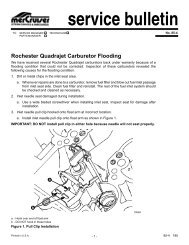
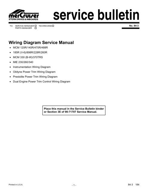
service bulletinTO: SERVICE MANAGER TECHNICIANSPARTS MANAGERNo. 84-3<strong>Wiring</strong> <strong>Diagram</strong> Service Manual• MCM 120R/140R/470R/488R• 185R (V-6)/898R/228R/260R• MCM 330 (B-W)/370TRS• MlE 230/260/340• Instrumentation <strong>Wiring</strong> <strong>Diagram</strong>• Oildyne Power Trim <strong>Wiring</strong> <strong>Diagram</strong>• Prestolite Power Trim <strong>Wiring</strong> <strong>Diagram</strong>• Dual Engine Power Trim Control <strong>Wiring</strong> <strong>Diagram</strong>Place this manual in the Service Bulletin binderor Section 3E of 90-71707 Service Manual.Printed in U.S.A.- 1 - 84-3 184
183-HMCM 120R/140R without Fuse84-3 184 - 2 -
183-HRRMCM 120R/140R with Fuse- 3 - 84-3 184
192-HMCM 470R/488R without Fuse84-3 184 - 4 -
192-HRRMCM 470R/488R with Fuse- 5 - 84-3 184
274-HMCM 185R (V-6)84-3 184 - 6 -
168-HMCM 898R/228R/260R without Fuse- 7 - 84-3 184
347-HMCM 898R with Fuse84-3 184 - 8 -
335-HRMCM 228R/260R with Fuse- 9 - 84-3 184
178-HMCM 330 (B-W) without Fuse84-3 184 - 10 -
178-HRMCM 330 (B-W) with Fuse- 11 - 84-3 184
MCM 370TRS84-3 184 - 12 -
NOTE: Taped back brown-white wire may be used for an accessory.LOAD MUST NOT EXCEED 5 AMPS.MIE 230/260/340 without Fuse- 13 - 84-3 184
NOTE: Taped back brownwhitewire may be used foran accessory. LOAD MUSTNOT EXCEED 5 AMPS.342-HMIE 230/260/340 with Fuse84-3 184 - 14 -
NOTE 1: Connect Wires Together with Screwand Hex Nut; Apply Liquid Neoprene to Connectionand Slide Rubber Sleeve over Connection.NOTE 2: Power for a Fused Accessory PanelMay Be Taken from This Connection. LoadMust Not Exceed 40 Amps. Panel GroundWire MUST BE Connected to Instrument TerminalThat Has an 8 Gauge Black (Ground)Harness Wire Connected to it.400-HInstrumentation <strong>Wiring</strong> <strong>Diagram</strong>- 15 - 84-3 184
NOTE: Early pumpswere equipped witha 20 amp circuitbreaker.334-HOildyne Power Trim <strong>Wiring</strong> <strong>Diagram</strong>84-3 184 - 16 -
465-HPrestolite Power Trim <strong>Wiring</strong> <strong>Diagram</strong>- 17 - 84-3 184
NOTE: 20-Amp Fuse or Circuit Breaker - Not Functional.Power Trim <strong>Wiring</strong> <strong>Diagram</strong> (with Dual Engine Power Trim Control)84-3 184 - 18 -