REMOVAL, INSTALLATION AND ADJUSTMENT - BoatFix.com
REMOVAL, INSTALLATION AND ADJUSTMENT - BoatFix.com
REMOVAL, INSTALLATION AND ADJUSTMENT - BoatFix.com
- No tags were found...

Create successful ePaper yourself
Turn your PDF publications into a flip-book with our unique Google optimized e-Paper software.
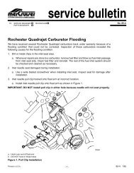
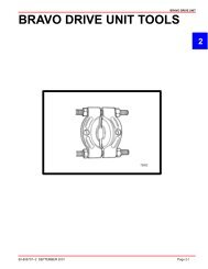
<strong>REMOVAL</strong>, <strong>INSTALLATION</strong> <strong>AND</strong> <strong>ADJUSTMENT</strong>S SERVICE MANUAL NUMBER 146. Remove power trim cylinders (aft end) from drive unit.bcade70027a -Aft Anchor Pinb-Bushings (4)c -Flat Washers (2)d-E-ring Clips (2)e -Plastic Caps (2)abba -Aft Anchor Pinb-Bushings70026Page 2A-4 90-818177--3 APRIL 2001
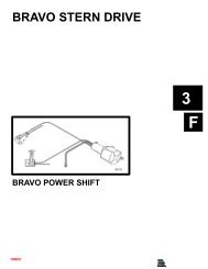
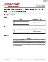
SERVICE MANUAL NUMBER 14<strong>REMOVAL</strong>, <strong>INSTALLATION</strong> <strong>AND</strong> <strong>ADJUSTMENT</strong>S7. Remove the 6 locknuts and 5 washers that hold the drive unit to the transom unit andremove sterndrive unit.babca -Locknuts (6)b-Washers (5)c -Ground Plate220628. Remove bell housing gasket.aa -Bell Housing Gasket7008590-818177--3 APRIL 2001 Page 2A-5
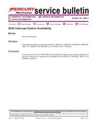
SERVICE MANUAL NUMBER 14<strong>REMOVAL</strong>, <strong>INSTALLATION</strong> <strong>AND</strong> <strong>ADJUSTMENT</strong>S6. Position bell housing shift slide so that slot in intermediate shaft coupler is positionedstraight fore and aft. Do this by placing remote control shift lever in: FORWARD gearWOT position for RH drive or REVERSE gear position for LH drive unit.75684aa7519975198a -Shift Shaft Slide Stabilizer Toolb-Shift SlidebIMPORTANT: Shift slide assembly is free to rotate on core wire. Therefore, be carefulthat shift slide remains in upright position and is properly engaged with shift shaftlever while installing drive unit.7. Position drive unit shift shaft so that is straight forward by turning shift shaft clockwisewhile simultaneously turning propeller shaft counterclockwise.a70033a -Drive Unit Shift Shaft CouplerIMPORTANT: Be sure to install RH or LH drive unit on the appropriate transomassembly when making dual engine installations. The LH rotation drive unit can beidentified by the decal on the back side of the upper drive shaft housing, whichstates: “Alpha One - Counter Rotation” or has an L on the propshaft90-818177--3 APRIL 2001 Page 2A-7
<strong>REMOVAL</strong>, <strong>INSTALLATION</strong> <strong>AND</strong> <strong>ADJUSTMENT</strong>S SERVICE MANUAL NUMBER 148. Place gasket on bell housing.aWithout Gear Lube Monitor(Shown Without Shift Slide Stabilizer Tool For Visual Clarity)a -Gasket70048NOTE: If equipped with Gear Lube Monitor BE SURE to install the gasket with the hole foroil passage.ab70048With Gear Lube Monitor(Shown Without Shift Slide Stabilizer Tool For Visual Clarity)a -Gasketb-Oil Passage Hole9. Install sterndrive unit:a. Position trim cylinder straight back (over top of acceleration plate). Be careful not toscratch acceleration plate or trim cylinders.b. Guide U-joint shaft through gimbal bearing and into engine coupler whilesimultaneously guiding shift slide into drive shaft housing. Make sure shift slideremains upright and engaged with bell housing shift shaft lever.c. After the U-joint shaft has begun to enter the engine coupler, remove the Shift SlideStabilizer Tool.Page 2A-8 90-818177--3 APRIL 2001
SERVICE MANUAL NUMBER 14<strong>REMOVAL</strong>, <strong>INSTALLATION</strong> <strong>AND</strong> <strong>ADJUSTMENT</strong>Sd. Ensure that the stud is thoroughly coated with Quicksilver 2-4-C Marine Lubricantwith Teflon.IMPORTANT: If drive unit will not slide all the way into bell housing, ensure shift shaftcouplers are positioned properly and all O-rings are greased. Do not force drive unitinto position.e. If necessary, rotate propeller shaft counterclockwise slightly to help align U-jointshaft splines with engine coupler splines. Then slide drive unit into bell housing.10. Secure drive unit to bell housings using fasteners as shown. Torque to 50 lb-ft (68 Nm).ab22062a -Locknut and Flat Washersb-Locknut and Continuity Circuit Washer (No Flat Washer at this Location)11. Return remote control shift lever to the neutral position.12. Install trim cylinders on aft end of drive unit with hardware as shown. Coat all<strong>com</strong>ponents, except plastic caps, with Quicksilver Special Lube 101 upon installation.Push-fit plastic caps onto ends of aft anchor pins.a. Insert one bushing in each inboard hole of both trim cylinders.b. Align the bores of the trim cylinders with that of the drive unit.c. Insert the aft anchor pin through one of the trim cylinders, the drive unit bore and thenthe other trim cylinder until it protrudes equally on both sides of the unit.90-818177--3 APRIL 2001 Page 2A-9
<strong>REMOVAL</strong>, <strong>INSTALLATION</strong> <strong>AND</strong> <strong>ADJUSTMENT</strong>S SERVICE MANUAL NUMBER 14NOTE: Distance between the trim cylinders and the drive unit anchor pin bore isexaggerated for visual clarity.abb70026a -Aft Anchor Pinb-Bushingsd. Install the two remaining bushings onto the aft anchor pin ends and fit into bore oftrim cylinders.e. Install the flat washers.f. Install the E-ring clips.NOTE: The inboard grooves of the aft anchor pin are for E-ring clips, and wider, outboardgrooves are for securing plastic caps.ceabd70027a -Aft Anchor Pinb-Bushingsc -Flat Washers (2)d-E-ring Clips (2)e -Plastic Caps (2)13. Raise drive to gain access to area between gimbal housing and sterndrive, immediatelyatop the transom end of the anti-ventilation plate.14. Connect speedometer fittings following a. or b. as appropriate:Page 2A-10 90-818177--3 APRIL 2001
SERVICE MANUAL NUMBER 14<strong>REMOVAL</strong>, <strong>INSTALLATION</strong> <strong>AND</strong> <strong>ADJUSTMENT</strong>Sa. Align the plastic fittings, push down and turn clockwise to engage locking device.aabcbc75580700251997-1/2 and Earlier Model Speedometer Connectora -Male End Of Speedometer Fittingb-Female End Of Speedometer Fittingc -Alignment Slots90-818177--3 APRIL 2001 Page 2A-11
<strong>REMOVAL</strong>, <strong>INSTALLATION</strong> <strong>AND</strong> <strong>ADJUSTMENT</strong>S SERVICE MANUAL NUMBER 14b. Push the release button and slide the female portion of the speedometer connectorover the male portion.bca75581a -Speedometer Connector, Female Endb-Bell Housingc -Sta-Strapcba755131998 and Later Model Speedometer Connectora -Speedometer Connector, Male Endb-Speedometer Connector, Female Endc -Gear HousingPage 2A-12 90-818177--3 APRIL 2001
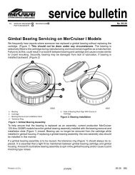
SERVICE MANUAL NUMBER 14<strong>REMOVAL</strong>, <strong>INSTALLATION</strong> <strong>AND</strong> <strong>ADJUSTMENT</strong>SRemote Control Shift Cable Adjustment (Drive Unit Installed)NOTE: The illustrations on the following pages show models that have a shift plate that ismounted on the exhaust elbow. The shift mechanism <strong>com</strong>ponents on the 3.0L model arelocated on the top of the valve cover or on the starboard harness bracket. The procedurefor making the adjustments is the same.IMPORTANT: Shift cable adjustment for a right hand (RH) rotation drive unit is differentthan the procedure for adjusting a left hand (LH) rotation drive unit. Be sure torefer to the appropriate procedure when performing the following steps.IMPORTANT: Drive unit must be installed.IMPORTANT: DO NOT run engine.1. Remove remote control shift cable and shift assist assembly (if installed).ba50308With Shift Assist Assemblya -Shift Assist Assemblyb-Remote Control Shift Cablea50310Without Shift Assist Assemblya -Remote Control Shift Cable90-818177--3 APRIL 2001 Page 2A-13
<strong>REMOVAL</strong>, <strong>INSTALLATION</strong> <strong>AND</strong> <strong>ADJUSTMENT</strong>S SERVICE MANUAL NUMBER 142. Ensure shift lever adjustable stud is located in the slot at the end closest to the shift leverpivot point. If necessary, loosen stud and align stud in the slot, then retighten stud.a -Adjustable Studa503093. Shift remote control as stated in a. or b.:a. Right Hand (RH) Rotation Drive Unit - forward gear, past detent, into wide-openthrottleposition.b. Left Hand (LH) Rotation Drive Unit - reverse gear, past detent, intowide-open-throttle position.(RH)(LH)4. Place drive unit into gear by pushing in on drive unit shift cable, while simultaneouslyrotating propeller shaft counterclockwise until shaft stops, to ensure full clutch engagement.Maintain a light pressure on the drive unit shift cable to hold it at the end of its travel(this removes all slack from the cable).Page 2A-14 90-818177--3 APRIL 2001
SERVICE MANUAL NUMBER 14<strong>REMOVAL</strong>, <strong>INSTALLATION</strong> <strong>AND</strong> <strong>ADJUSTMENT</strong>SIMPORTANT: Do not use excessive force when holding pressure on the drive unitshift cable. Excessive force would be indicated by movement of the V-notch of theactuator lever assembly.ab22266a -Drive Unit Shift Cable - Push Inb-Propeller Shaft - Rotate Counterclockwise5. Lightly pull on remote control shift cable end guide (to remove slack from remote controland cable) and adjust brass barrel as necessary to align attaching points with shift leverclevis pin hole and stud. Be sure to maintain light pressure on drive unit shift cable.cadb50309a -End Guideb-Brass Barrelc -Shift Lever Clevis Pin Holed-Stud90-818177--3 APRIL 2001 Page 2A-15
<strong>REMOVAL</strong>, <strong>INSTALLATION</strong> <strong>AND</strong> <strong>ADJUSTMENT</strong>S SERVICE MANUAL NUMBER 146. After cable has been aligned, turn brass barrel 4 turns away from cable end guide.bae -End Guidef -Brass Barrel7. Temporarily install remote control shift cable on stud and install clevis pin.50308ba -Remote Control Shift Cableb-Clevis Pina503088. Shift remote control as stated in a. or b. :a. Right Hand (RH) Rotation Drive Unit - reverse gear, past detent, into wide-openthrottleposition.b. Left Hand (LH) Rotation Drive Unit - forward gear, past detent, into wide-openthrottleposition.(RH)(LH)Page 2A-16 90-818177--3 APRIL 2001
SERVICE MANUAL NUMBER 14<strong>REMOVAL</strong>, <strong>INSTALLATION</strong> <strong>AND</strong> <strong>ADJUSTMENT</strong>S9. Simultaneously rotate propeller shaft clockwise until shaft stops to ensure full clutch engagement.a22267a -Propeller Shaft - Rotate Clockwise10. Perform a. or b. as appropriate:a. On Models with Earlier Type Switch: check shift cutout switch lever position. Rollermust be centered.a22058a -Shift Cutout Switch Rollerb. On Models with Later Type Switch: check shift cutout switch plunger position. Pinmust be centered.aa -Shift Cutout Switch Plunger90-818177--3 APRIL 2001 Page 2A-177512811. If roller or plunger pin is not centered:a. Ensure adjustable stud is at bottom of slot in shift lever.b. Check remote control for proper shift cable output [3 in. (76 mm) ± 1/8 in. (3 mm)].c. If a and b are correct, ensure drive unit shift cable is not crushed or kinked. (If driveunit shift cable is binding, the shift cutout switch roller or plunger pin will move offcenter when shifting “into” and “out of” forward and reverse).
<strong>REMOVAL</strong>, <strong>INSTALLATION</strong> <strong>AND</strong> <strong>ADJUSTMENT</strong>S SERVICE MANUAL NUMBER 14NOTE: If shift cable was damaged during installation, install new shift cable assembly, thenrepeat shift cable adjustment procedure.CAUTIONImproper installation of the shift assist assembly could result in damage or malfunctionto the shift control box.For Commander 3000 Controls, if shift assist assembly attaching points do not align, verifycontroller is in the neutral position. Remove the shift cable and reposition the adjustmentbarrel as required to allow the shift assembly to be installed with no effort.For ALL other controls, if shift assist assembly attaching points do not align, push in orpull out on end of shift assist assembly to install. Do not attempt to readjust shift cable.Page 2A-18 90-818177--3 APRIL 2001
SERVICE MANUAL NUMBER 14<strong>REMOVAL</strong>, <strong>INSTALLATION</strong> <strong>AND</strong> <strong>ADJUSTMENT</strong>S12. After remote control shift cable has been properly adjusted, reinstall cable and shift assistassembly (if applicable) and secure with hardware. Tighten locknut <strong>com</strong>pletely thenback off 1/2 turn.daefbgWith Shift Assist Assemblya -Remote Control Shift Cableb-Shift Assist Assemblyc -Clevis Pind-Cotter Pine -Large I.D. Washerf -Small I.D. Washerg-Locknutc5030890-818177--3 APRIL 2001 Page 2A-19
<strong>REMOVAL</strong>, <strong>INSTALLATION</strong> <strong>AND</strong> <strong>ADJUSTMENT</strong>S SERVICE MANUAL NUMBER 14cadbghife50310Without Shift Assist Assemblya -Remote Control Shift Cableb-Clevis Pinc -Cotter Pind-Springe -Washerf -Washerg-Spacerh-Washeri -LocknutIMPORTANT: If an extra long remote control shift cable is used, or if there are a largenumber of bends in remote control shift cable, or remote control has inadequate outputtravel, an additional adjustment may be necessary. Refer to step 13 or 14 as applicable.13. Remote Control with Single Lever Shift/Throttle Control:a. RIGHT H<strong>AND</strong> (RH) propeller rotation drive unit - Shift remote control into reversegear, wide-open-throttle position while simultaneously rotating propeller shaft clockwise.Clutch should engage and cause propeller shaft to lock. If clutch does not engage,loosen adjustable stud on shift lever and move it upward in slot until clutchengages with reverse gear. Retighten stud. Shift remote control several times andstop in reverse to recheck shift cutout switch position. Roller or pin must be centered.b. LEFT H<strong>AND</strong> (LH) propeller rotation drive unit - Shift remote control into forwardgear, wide-open-throttle position while simultaneously rotating propeller shaft clockwise.Clutch should engage and cause propeller shaft to lock. If clutch does not engage,loosen adjustable stud on shift lever and move it upward in slot until clutchengages with forward gear. Retighten stud. Shift remote control several times andstop in forward to recheck shift cutout switch position. Roller or pin must be centered.14. Two Lever Remote Control with Separate Shift and Throttle Levers:a. RIGHT H<strong>AND</strong> (RH) propeller rotation drive unit - While turning propeller shaftclockwise, move remote control shift handle into full reverse position. Clutch shouldengage before shift lever <strong>com</strong>es to a stop. If clutch does not engage, loosen adjustablestud on shift lever and move it upward in slot until clutch engages with reversegear. Retighten stud. Shift remote control several times and stop in reverse to recheckshift cutout switch position. Roller or pinmust be centered.b. LEFT H<strong>AND</strong> (LH) propeller rotation drive unit - While turning propeller shaftclockwise, move remote control shift handle into full forward position. Clutch shouldPage 2A-20 90-818177--3 APRIL 2001
SERVICE MANUAL NUMBER 14<strong>REMOVAL</strong>, <strong>INSTALLATION</strong> <strong>AND</strong> <strong>ADJUSTMENT</strong>Sengage before shift lever <strong>com</strong>es to a stop. If clutch does not engage, loosen adjustablestud on shift lever and move it upward in slot until clutch engages with forwardgear. Retighten stud. Shift remote control several times and stop in forward to recheckshift cutout switch position. Roller or pin must be centered.a50309a -Adjustable Studaa -Shift Cutout Switch Roller22058aa -Shift Cutout Switch Plunger7512890-818177--3 APRIL 2001 Page 2A-21
<strong>REMOVAL</strong>, <strong>INSTALLATION</strong> <strong>AND</strong> <strong>ADJUSTMENT</strong>S SERVICE MANUAL NUMBER 14Troubleshooting Shift ProblemsNOTE: The following information is provide to assist an installer in troubleshooting if hardshifting or chucking/racheting is encountered when shifting into FORWARD gear.1. When installing the control box in the side panel of the boat, make sure that the cableshave enough clearance to operate. This is necessary because the cables move up anddown when the shift handle is moved. If the control box is mounted too far back towardsany fiberglass structure, the cables will be interfered with, this will cause very hardshifting.NOTE: The control box housing can be rotated in 30° increments to improve cable routing.7468874689Proper Cable BendImproper Cable Bend2. Ensure that when the shift cable from the control box is led through the side gunnel ofthe hull, it does not have any extremely sharp bends in it as this will cause the stiffshifting.3. Before installing the shift cable into the control box, extend the stainless rod eye end ofthe cable and grease it with 2-4-C Marine Lubricant with Teflon. Move it back and forthto allow even distribution of the grease.220054. Do not strap or clamp the control cables to any other cables or rigid structure within 3ft. (914 mm) of the control box.5. Be sure the cable is not permanently kinked.6. Make sure there is proper clearance for cable movement when the control box isinstalled in the side panel. The cables must have room to move up and down when thecontrol handle is shifted into either FORWARD or REVERSE.7. Ensure that the engine was not set down on the intermediate shift cable duringinstallation, as this will crush the inner cable tubing and cause improper and / or stiffshifting.Page 2A-22 90-818177--3 APRIL 2001
SERVICE MANUAL NUMBER 14<strong>REMOVAL</strong>, <strong>INSTALLATION</strong> <strong>AND</strong> <strong>ADJUSTMENT</strong>S8. DO NOT fasten the shift cable with straps or clamps to any other cable within 5 ft. (1524mm) of the shift plate.9. DO NOT fasten the shift cable to the transom with any type of plastic clips or fastenerswithin 5 ft. (1524 mm) of the shift plate.10. DO NOT overtighten the throttle or shift cable attaching nuts at the engine end. Barreland cable end must be free to rotate on the mounting stud.11. Check the intermediate shift cable routing from the transom assembly to the shift plateas follows:a. The cable should <strong>com</strong>e through the transom, above the exhaust pipe and make aturn towards the starboard side of the boat between the exhaust pipe and the engineflywheel housing.b. The cable should then be routed under the starboard rear engine mount, and turntowards the transom.c. Then go up behind the power steering valve and loop over to the shift plate on theengine, where it is connected to the anchor points on the shift plate.Following this routing will prevent the engine coupler from damaging the cable.74903749014 Cylinder Inline Model V6 and V8 ModelsPropeller InstallationWARNINGBe sure that remote control is in the neutral position and ignition key is removedfrom switch.WARNINGPlace a block of wood between the antiventilation plate to protect hands from propellerblades and to prevent propeller from turning.1. To aid in future propeller removal, liberally coat the propeller shaft splines with one ofthe following lubricants; then, install propeller.• Special Lubricant 101• 2-4-C Marine Lubricant with Teflon• Perfect Seal90-818177--3 APRIL 2001 Page 2A-23
<strong>REMOVAL</strong>, <strong>INSTALLATION</strong> <strong>AND</strong> <strong>ADJUSTMENT</strong>S SERVICE MANUAL NUMBER 14IMPORTANT: Installation is correct when at least 2 threads of propeller shaft areexposed through propeller nut.aefbcdg22074Propeller Without Flo-Torq II Drive Huba -Propeller Shaftb-Forward Thrust Hubc -Propellerd-Continuity Washere -Spline Washerf -Tab Washerg-Propeller Nutabcdef70134Propeller With Flo-Torq II Drive Huba -Propeller Shaftb-Forward Thrust Hubc -Flo Torq II Drive Hubd-Propellere -Drive Sleeve Adapter and Locking Tab Washerf -Propeller Nut2. Torque propeller nut until 55 lb-ft (75 Nm) is obtained and continue until 3 tabs on tabwasher align with grooves on drive sleeve.3. Bend tabs into drive sleeve.Page 2A-24 90-818177--3 APRIL 2001
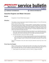
SERVICE MANUAL NUMBER 14Transom Assembly Removal<strong>REMOVAL</strong>, <strong>INSTALLATION</strong> <strong>AND</strong> <strong>ADJUSTMENT</strong>SPower Steering ModelsNOTE: If Tie Bars need to be removed or serviced see section 6A or 6B.1. Remove the power steering assembly..a. Disconnect clevis from steering lever.b. Disconnect steering cable from clevis.digbabdchgacfef2202371901Earlier Model Control Valvea -Cable Endb-Clevisc -Cotter Pind-Clevis Pine -Locking Platef -Cable Retaining Nutg-Steering Leverh-Cotter Pini -Clevis Pin. . . . . . . . . . .Later Model Control Valve90-818177--3 APRIL 2001 Page 2A-25
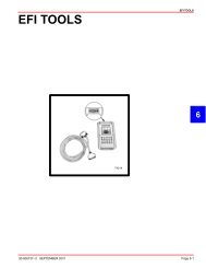
<strong>REMOVAL</strong>, <strong>INSTALLATION</strong> <strong>AND</strong> <strong>ADJUSTMENT</strong>S SERVICE MANUAL NUMBER 14c. Bend tabs away from pivot bolts then loosen bolts and remove power steering unit.cbaca -Power Steering Unitb-Tab Washerc -Pivot Boltb23256Manual Steering Models1. Remoe the manual steering assembly.a. Disconnect steering cable or clevis from steering lever.adcb22055a -Steering Leverb-Steering Cablec -Cotter Pind-Clevis PinPage 2A-26 90-818177--3 APRIL 2001
SERVICE MANUAL NUMBER 14<strong>REMOVAL</strong>, <strong>INSTALLATION</strong> <strong>AND</strong> <strong>ADJUSTMENT</strong>Sb. Bend tabs away from pivot bolts. Loosen bolts and remove manual steering swivelring.bcabc22945a -Swivel Ringb-Tab Washerc -Pivot Bolt2. Disconnect gear lube monitor hose, if equipped. Plug hose and cap fitting.abab7002377712. . . . . . . . . . . . Earlier Style . . . . . . . . . . . . . . . . . . . . . . . . . .a -Hoseb-Hose ClampLater Style3. Disconnect speedometer hose, if equipped.aa -Speedometer Fitting700154. Disconnect MerCathode wires from control unit on engine, if equipped.90-818177--3 APRIL 2001 Page 2A-27
<strong>REMOVAL</strong>, <strong>INSTALLATION</strong> <strong>AND</strong> <strong>ADJUSTMENT</strong>S SERVICE MANUAL NUMBER 145. Disconnect trim limit switch wires at trim pump and trim position sender wires at engine.6. For engine removal, refer to appropriate engine service manual.7. Disconnect power trim hydraulic hoses from trim pump. Cap hoses and plug pump fittingholes.cba -Sta-Strapb-Trim Limit Switch Wiresc -Hydraulic Hosesa22031Page 2A-28 90-818177--3 APRIL 2001
SERVICE MANUAL NUMBER 148. If installed, remove exhaust pipe.<strong>REMOVAL</strong>, <strong>INSTALLATION</strong> <strong>AND</strong> <strong>ADJUSTMENT</strong>Sab70068In-line 4 Cylinder Modelsba22057V6/V8 Modelsa -Exhaust Pipeb-Screws90-818177--3 APRIL 2001 Page 2A-29
<strong>REMOVAL</strong>, <strong>INSTALLATION</strong> <strong>AND</strong> <strong>ADJUSTMENT</strong>S SERVICE MANUAL NUMBER 149. Remove ground wire from steering lever.cba22028a -Steering Leverb-Ground Wirec -ScrewsCAUTIONTransom gimbal housing (on outside of boat must be secured prior to the next stepto prevent dropping.10. Remove all nuts, bolts and washers (items “a” and “h” in diagram) and separate innertransom plate from transom gimbal housing.11. Remove transom gimbal housing from transom of boat.afdfeaach70012bga -Flat Washers and Locknutsb-Hydraulic Hosesc -Drive Unit Shift Cabled-Trim Limit And Trim Position Sender Wirese -Inner Transom Platef -Ground Wire (Continuity Circuit)g-MerCathode Wires (If Equipped)h-Long Screws, Lock Washers And Square Flat Washers (Later Models - StudsWith Locknuts And Flat Washers)Page 2A-30 90-818177--3 APRIL 2001
SERVICE MANUAL NUMBER 14Transom Assembly Installation<strong>REMOVAL</strong>, <strong>INSTALLATION</strong> <strong>AND</strong> <strong>ADJUSTMENT</strong>SCAUTIONOn earlier style transom assembly with carriage bolts at the bottom, rubber sealMUST BE installed on the bolts or water will leak into boat.ba -Carriage Boltb-Rubber Seala22028CAUTIONSteering lever ground wire MUST BE positioned as shown or wire may fatigue.bca22028a -Steering Leverb-Inner Transom Platec -Ground WireIMPORTANT: Be sure to pull all wires and cables <strong>com</strong>pletely through inner transomplate and ensure wires are not pinched when installing gimbal housing to transom.IMPORTANT: Torque bolts and nuts evenly (starting from center and working out) to22.5 lb-ft (30.5 Nm).90-818177--3 APRIL 2001 Page 2A-31
<strong>REMOVAL</strong>, <strong>INSTALLATION</strong> <strong>AND</strong> <strong>ADJUSTMENT</strong>S SERVICE MANUAL NUMBER 141. Install transom assembly. Tighten attaching bolts and nuts evenly (starting from centerand working out). Torque to 22.5 lb-ft (30.5 Nm).afdfeaachbga -Flat Washers and Locknutsb-Hydraulic Hosesc -Drive Unit Shift Cabled-Trim Limit And Trim Position Sender Wirese -Inner Transom Platef -Ground Wire (Continuity Circuit)g-MerCathode Wires (If Equipped)h-Carriage Bolts With Flat Washers And Locknuts (Later Models - Studs, FlatWashers And Locknuts)700122. If equipped, connect gear lube monitor hose.abab7002377712. . . . . . . . . . . . Earlier Style . . . . . . . . . . . . . . . . . . . . . . . . . .a -Hoseb-Hose ClampLater StylePage 2A-32 90-818177--3 APRIL 2001
SERVICE MANUAL NUMBER 14<strong>REMOVAL</strong>, <strong>INSTALLATION</strong> <strong>AND</strong> <strong>ADJUSTMENT</strong>S3. If equipped, connect hose from the speedometer to the barb fitting and secure with cabletie.aa -Barb Fitting70015IMPORTANT: Exhaust pipe and gimbal housing mating surfaces must be clean andfree of nicks and scratches or exhaust may leak into boat.aba -O-ring Sealb-Mating Surface220574. If equipped, glue O-ring seal to gimbal housing.90-818177--3 APRIL 2001 Page 2A-33
<strong>REMOVAL</strong>, <strong>INSTALLATION</strong> <strong>AND</strong> <strong>ADJUSTMENT</strong>S SERVICE MANUAL NUMBER 145. Install exhaust pipe or block off plate on gimbal housing. Torque screws to 22.5 lb-ft(30.5 Nm).ab70068In-line 4 Cylinder Modelsba22057V6/V8 Modelsa -Exhaust Pipeb-ScrewsPage 2A-34 90-818177--3 APRIL 2001
SERVICE MANUAL NUMBER 14<strong>REMOVAL</strong>, <strong>INSTALLATION</strong> <strong>AND</strong> <strong>ADJUSTMENT</strong>S6. If using through-transom exhaust, install block off plate and O-ring seal. Torque to22.5 lb-ft (30.5 Nm)ba22057Models with Through The Transom Exhausta -Block Off Plateb-ScrewsCAUTIONDO NOT cross thread or overtighten hose fittings when making hydraulic hose connectionsto power trim pumps.IMPORTANT: Make hydraulic hose connections as quickly as possible to prevent oilfrom leaking out of trim system.7. Connect power trim pump hydraulic hoses. Torque to 125 lb-in. (14.1 Nm).badc22031a -Black Hose (Up Hose)b-Gray Hose (Down Hose)c -Trim Limit Switch Wiresd-Wire Retainer and Sta-Strap8. Connect trim limit switch wires.90-818177--3 APRIL 2001 Page 2A-35
<strong>REMOVAL</strong>, <strong>INSTALLATION</strong> <strong>AND</strong> <strong>ADJUSTMENT</strong>S SERVICE MANUAL NUMBER 14Power Steering Models1. Install power steering assembly on inner transom plate.a. Lubricate power steering unit bushings with Special Lubricant 101.aa -Power Steering Unit Bushings71901b. Slide power steering unit bushings between transom plate mounting brackets.Install two pivot bolts and at the same time, slightly move (wiggle) steering unit toensure proper pivot bolt engagement into bushings. Ensure washer tangs straddleridges on inner transom plate.acbbaca -Pivot Boltsb-Washer Tangsc -Ridges22168c. Torque pivot bolts to 25 lb-ft (34 Nm). Bend washer tabs against flat on bolt heads.2. If equipped, connect power steering unit clevis to steering lever as follows:a. Lubricate clevis pin with Special Lubricant 101.b. Install clevis pin through clevis and steering lever from top.Page 2A-36 90-818177--3 APRIL 2001
SERVICE MANUAL NUMBER 14c. Secure clevis pin with cotter pin. Bend both ends of cotter pin.<strong>REMOVAL</strong>, <strong>INSTALLATION</strong> <strong>AND</strong> <strong>ADJUSTMENT</strong>Sbcad70019a -Clevis Pinb-Clevisc -Steering Leverd-Cotter PinWARNINGFailure to use a steering cable locking device could cause a loss of steering, whichcould cause damage to the boat and/or injury.All current production Quicksilver Ride Guide steering cables have a self-locking couplernut and do not require an external locking device. (Other cable manufacturers also makecables with a self-locking coupler nut.)3. Install steering cable.a. Lubricate steering cable end with a liberal amount of Special Lubricant 101 andinstall cable end through guide tube.b. Later Model Control Valve: Using a suitable wrench, hold the flat surfaces on thecable guide tube in the vertical position.abc73901Later Model Control Valvea -Flat (Hold Vertical)b-Suitable Wrenchc -Guide Tubec. Both Models: Connect cable end to clevis with clevis pin. Secure clevis pin in cleviswith cotter pin. Bend both ends of cotter pin.90-818177--3 APRIL 2001 Page 2A-37
<strong>REMOVAL</strong>, <strong>INSTALLATION</strong> <strong>AND</strong> <strong>ADJUSTMENT</strong>S SERVICE MANUAL NUMBER 14d. Tighten cable coupler nut. Torque to 35 lb-ft (48 Nm).NOTE: On later models, manually hold the guide tube while tightening the coupler nut.e. Earlier Model Control Valve: If required, install locking plate on coupler nut andsecure with screw and washer. Torque to 66 lb-in. (7.5 Nm).NOTE: Later model control valves DO NOT have a locking plate.digbabdchgacfef2202371901Earlier Model Control Valvea -Cable Endb-Clevisc -Cotter Pind-Clevis Pine -Locking Platef -Cable Retaining Nutg-Steering Leverh-Cotter Pini -Clevis Pin. . . . . . . . . . .Later Model Control ValveManual Steering Models1. Install manual steering assembly on inner transom plate.a. Lubricate swivel ring bushings with Special Lubricant 101.a22946a -Swivel Ring Bushingsb. Slide manual steering swivel ring and bushings between transom plate mountingbrackets. Install two pivot bolts and at the same time, slightly move (wiggle) swivelPage 2A-38 90-818177--3 APRIL 2001
SERVICE MANUAL NUMBER 14<strong>REMOVAL</strong>, <strong>INSTALLATION</strong> <strong>AND</strong> <strong>ADJUSTMENT</strong>Sring to ensure proper pivot bolt engagement into swivel ring bushings. Ensurewasher tangs straddle ridges on inner transom plate.acbbaa -Pivot Boltsb-Washer Tangsc -Ridgesc22168c. Torque pivot bolts to 25 lb-ft (34 Nm). Bend washer tabs against flat on bolt heads.2. Install steering cable.a. Lubricate steering cable end with a liberal amount of Special Lubricant 101 andinstall cable end through guide tube.b. Connect steering cable to steering lever and secure with clevis pin and cotter pin.Spread both ends of cotter pin.c. Tighten coupler nut. Torque to 35 lb-ft (48 Nm).bgfacde70373a -Steering Cableb-Cable Coupler Nutc -Steering Cable Guide Tubed-Steering Cable Ende -Cotter Pinf -Clevis Ping-Steering Lever90-818177--3 APRIL 2001 Page 2A-39
<strong>REMOVAL</strong>, <strong>INSTALLATION</strong> <strong>AND</strong> <strong>ADJUSTMENT</strong>S SERVICE MANUAL NUMBER 14THIS PAGE IS INTENTIONALLY BLANKPage 2A-40 90-818177--3 APRIL 2001