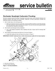
gasoline engine sterndrive models installation manual - BoatFix.com
gasoline engine sterndrive models installation manual - BoatFix.com
gasoline engine sterndrive models installation manual - BoatFix.com

You also want an ePaper? Increase the reach of your titles
YUMPU automatically turns print PDFs into web optimized ePapers that Google loves.
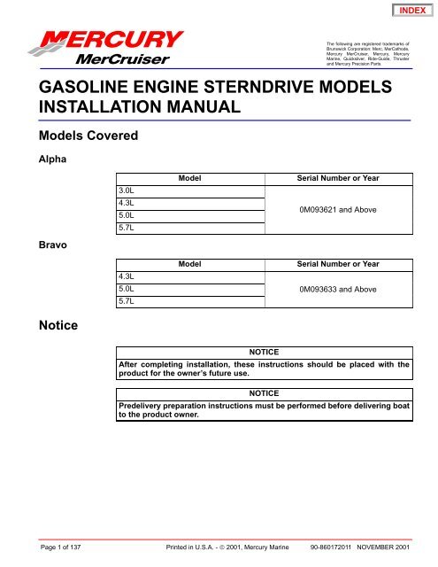
The following are registered trademarks ofBrunswick Corporation: Merc, MerCathode,Mercury MerCruiser, Mercury, MercuryMarine, Quicksilver, Ride-Guide, Thrusterand Mercury Precision Parts.GASOLINE ENGINE STERNDRIVE MODELSINSTALLATION MANUALModels CoveredAlpha3.0L4.3L5.0L5.7LModelSerial Number or Year0M093621 and AboveBravoModelSerial Number or Year4.3L5.0L 0M093633 and Above5.7LNoticeNOTICEAfter <strong>com</strong>pleting <strong>installation</strong>, these instructions should be placed with theproduct for the owner’s future use.NOTICEPredelivery preparation instructions must be performed before delivering boatto the product owner.Page 1 of 137 Printed in U.S.A. - © 2001, Mercury Marine 90-860172011 NOVEMBER 2001
GASOLINE STERNDRIVE INSTALLATION MANUALTable Of ContentsGeneral Information . . . . . . . . . . . . . . . . . 3Notice to Boat Manufacturer/Installer . . . . . 3Torque Specifications . . . . . . . . . . . . . . . . . . . . . 4Lubricants / Sealants / Adhesives . . . . . . . . . . 5Special Tools . . . . . . . . . . . . . . . . . . . . . . . . . . . . 6Alpha Notice: Increased Trim-In RangeCapability . . . . . . . . . . . . . . . . . . . . . . . . . . . . . . 6Bravo Three Notice: Trim-In Limit Insert . . . . . 7Quicksilver Products . . . . . . . . . . . . . . . . . . . . . . 7Accessories . . . . . . . . . . . . . . . . . . . . . . . . . . . 7Serial Number Decal Placement . . . . . . . . . . . . 8Corrosion Protection . . . . . . . . . . . . . . . . . . . . . . 8Anti-fouling Paint . . . . . . . . . . . . . . . . . . . . . . 9Boat Construction . . . . . . . . . . . . . . . . . . . . . . . 10Transom Thickness and Surface . . . . . . . . 10Engine Bed . . . . . . . . . . . . . . . . . . . . . . . . . . . 11Crankshaft Vertical Centerline . . . . . . . . . . . 11Crankshaft Horizontal Centerline(X-Dimension) . . . . . . . . . . . . . . . . . . . . . . 12Transom Cutout . . . . . . . . . . . . . . . . . . . . . . 14Seawater Connections - GeneralInformation . . . . . . . . . . . . . . . . . . . . . . . . . . . . 16Seawater Pickup . . . . . . . . . . . . . . . . . . . . . 16Preliminary Connections . . . . . . . . . . . . . . . . . 18Power Trim Pump . . . . . . . . . . . . . . . . . . . . 18Fuel Inlet Fitting . . . . . . . . . . . . . . . . . . . . . . 19Transom Connections . . . . . . . . . . . . . . . . . . . 20Installing Gimbal Housing . . . . . . . . . . . . . . 20Installing Inner Transom Plate . . . . . . . . . . 21Connecting Speedometer Pickup . . . . . . . 22Fluid Connections . . . . . . . . . . . . . . . . . . . . 23Installing Steering System . . . . . . . . . . . . . 25Transom Preparation . . . . . . . . . . . . . . . . . . 35Driveshaft Extension Models . . . . . . . . . . . . . . 39Engine Preparation . . . . . . . . . . . . . . . . . . . . . . 39Engine Installation . . . . . . . . . . . . . . . . . . . . . . . 40Exhaust System . . . . . . . . . . . . . . . . . . . . . . 43Methods for Measuring ExhaustElbow Height . . . . . . . . . . . . . . . . . . . . . . . 46Exhaust System Hose / TubeConnections . . . . . . . . . . . . . . . . . . . . . . . . 48Engine Alignment . . . . . . . . . . . . . . . . . . . . . 49Hot Water Heater Installation . . . . . . . . . . . 53Electrical Connections . . . . . . . . . . . . . . . . . . . 55Installing Continuity Wire . . . . . . . . . . . . . . 55Instrumentation Connections . . . . . . . . . . . 56Trim Position Sender Connections . . . . . . 57MerCathode Connections . . . . . . . . . . . . . . 57Audio Warning System Connections . . . . 58Power Trim Pump Connections . . . . . . . . . 59Fluid Connections . . . . . . . . . . . . . . . . . . . . . . . 61Gear Lube Monitor Hose . . . . . . . . . . . . . . 61Power Steering Hoses . . . . . . . . . . . . . . . . 62Bravo Models and Alpha SeawaterCooled Models Using SterndriveWater Pickups . . . . . . . . . . . . . . . . . . . . . . 62Alpha or Bravo Models UsingAlternative Water Pickups . . . . . . . . . . . . 63Coolant Recovery System . . . . . . . . . . . . . 66Shift Cable Installation . . . . . . . . . . . . . . . . . . . 67Alpha Models - Drive Unit NotInstalled . . . . . . . . . . . . . . . . . . . . . . . . . . . . 67Bravo Models . . . . . . . . . . . . . . . . . . . . . . . . 72Throttle Cable Installation andAdjustment . . . . . . . . . . . . . . . . . . . . . . . . . . . . 76Sterndrive Unit Installation . . . . . . . . . . . . . . . . 77Alpha Models . . . . . . . . . . . . . . . . . . . . . . . . 79Bravo Models . . . . . . . . . . . . . . . . . . . . . . . . 82All Models . . . . . . . . . . . . . . . . . . . . . . . . . . . 86Speedometer Connection . . . . . . . . . . . . . . . . 87Alpha Models . . . . . . . . . . . . . . . . . . . . . . . . 87Bravo Models . . . . . . . . . . . . . . . . . . . . . . . . 88Shift Cable Installation . . . . . . . . . . . . . . . . . . . 89Alpha Models - Drive Unit Installed . . . . . . 89Troubleshooting Shift Problems . . . . . . . . . 95Predelivery Preparation . . . . . . . . . . . . . . . . . . 98Power Steering Fluid . . . . . . . . . . . . . . . . . . 98Filling Coolant Recovery Bottle . . . . . . . . . 99Power Trim Pump . . . . . . . . . . . . . . . . . . . . 99Trim Position Sender Adjustment . . . . . . 100Propeller Selection . . . . . . . . . . . . . . . . . . . 101Propeller Installation . . . . . . . . . . . . . . . . . 102Battery . . . . . . . . . . . . . . . . . . . . . . . . . . . . . 106Test Running Engine . . . . . . . . . . . . . . . . . 107Boat In The Water Tests . . . . . . . . . . . . . . . 111Cold Weather and Extended Storage . . . . . 114Draining Instructions . . . . . . . . . . . . . . . . . . . . 1143.0L Single Point Drain . . . . . . . . . . . . . . . 115V6 And V8 Seawater (Raw-Water)Cooled Models . . . . . . . . . . . . . . . . . . . . . 119V6 And V8 Closed Cooled Models . . . . . 122All Models . . . . . . . . . . . . . . . . . . . . . . . . . . 124Wiring Diagrams . . . . . . . . . . . . . . . . . . . . . . . 126Instrumentation . . . . . . . . . . . . . . . . . . . . . . 126Power Trim System . . . . . . . . . . . . . . . . . . . . . 128MerCathode System Wiring Diagram . . . . . 129MCM Gasoline Engine Wiring Diagrams . . . 1303.0L Engines . . . . . . . . . . . . . . . . . . . . . . . . 130MCM 4.3L, 5.0L And 5.7L AlphaEngines . . . . . . . . . . . . . . . . . . . . . . . . . . . 131MCM 4.3L Bravo Engines . . . . . . . . . . . . . 132MCM 5.0L and 5.7L Bravo Engines . . . . 133Water Flow Diagrams . . . . . . . . . . . . . . . . . . . 134181 cid / 3.0L Engines . . . . . . . . . . . . . . . . 134V8 Engines - Seawater Cooled . . . . . . . . 135V6 and V8 Engines - Closed Cooled . . . 136Predelivery Inspection . . . . . . . . . . . . . . . . . . 137Page 2 of 137 90-860172011
General InformationGASOLINE STERNDRIVE INSTALLATION MANUALNotice to Boat Manufacturer/InstallerThroughout this publication, Warnings and Cautions (ac<strong>com</strong>panied by the InternationalHazard Symbol ! ) are used to alert the manufacturer or installer to special instructionsconcerning a particular service or operation that may be hazardous if performed incorrectlyor carelessly. –– Observe Them Carefully!These Safety Alerts, alone, cannot eliminate the hazards that they signal. Strict <strong>com</strong>plianceto these special instructions when performing the service, plus <strong>com</strong>mon sense operation,are major accident prevention measures.WARNINGHazards or unsafe practices which could result in severe personal injury or death.CAUTIONHazards or unsafe practices which could result in minor personal injury or productor property damage.IMPORTANT: Indicates information or instructions that are necessary for proper<strong>installation</strong> and/or operation.NOTE: Refer to the Mercury MerCruiser Product Applications Manual - Gasoline SterndriveModels for application re<strong>com</strong>mendations.This <strong>installation</strong> <strong>manual</strong> has been written and published by Mercury Marine to aid the boatmanufacturer (OEM) in the <strong>installation</strong> of the products described herein.It is assumed that these personnel are familiar with marine product <strong>installation</strong>.Furthermore, it is assumed that they are familiar with, if not trained in, the re<strong>com</strong>mended<strong>installation</strong> procedures of Mercury MerCruiser product.We could not possibly know of or advise the marine trade of all conceivable <strong>installation</strong>s andof the possible hazards and/or results of each <strong>installation</strong>. Therefore, the OEM isresponsible for any <strong>installation</strong> that does not fulfil the requirements of this <strong>manual</strong>.It is the responsibility of the boat manufacturer to select the appropriate<strong>engine</strong>/transom/drive package (including the correct gear ratio and propeller) for a givenboat. Mercury re<strong>com</strong>mends that any new or unique hull/power package <strong>com</strong>bination bethoroughly water tested prior to sale, to verify that the boat performs as desired, and thatthe <strong>engine</strong> runs in the appropriate rpm range.It is re<strong>com</strong>mended that a Mercury Marine Sales Application Engineer (SAE) be contactedfor assistance.All information, illustrations and specifications contained in this <strong>manual</strong> are based on thelatest product information available at time of publication. As required, revisions to this<strong>manual</strong> will be sent to all OEM boat <strong>com</strong>panies.90-860172011 Page 3 of 137
GASOLINE STERNDRIVE INSTALLATION MANUALTorque SpecificationsNOTE: Securely tighten all fasteners not listed below.Description Nm lb-in. lb-ftGear Lube Monitor Fitting 9 80Speedometer Pickup Barb Fitting 1.5 13Exhaust Pipe or Block-off Plate 31 23Power Steering Hydraulic Hose Fittings 31 23Power Trim Pump Hose Fittings 14 125Propeller Nut Alpha One, Bravo One and Bravo Two 1 75 55Front Propeller Nut Bravo Three 136 100Rear Propeller Nut Bravo Three 81 60Rear Engine Mounts 51 38Steering Cable Coupler Nut 48 35Steering System (Pivot Bolts) 34 25Sterndrive Unit Fasteners 68 50Transom Assembly Fasteners 31 23Seawater Pickup Fitting 5 45Finger tight + 1-3/4 toFuel Inlet Fitting2-1/4 turns with a wrench.DO NOT overtighten.1 Amount specified is MINIMUM.Page 4 of 137 90-860172011
Lubricants / Sealants / AdhesivesGASOLINE STERNDRIVE INSTALLATION MANUALDescription Where Used Part NumberEngine Coupler Spline Grease2-4-C Marine Lubricant WithTeflonCoupler SplinesDrive Unit PilotU-Joint O-ringsDrive Shaft SplinesAnchor PinsTrim Cylinder Hardware92-816391A4O-ring Seals 92-825407A3Shift Cable EndPropeller SplinesPivot BoltsPower Steering BushingsSpecial Lubricant 101 Clevis Pin 92-13872A1Steering Cable EndPropeller SplinesDexron III - AutomaticTransmission FluidPower Steering Pump Obtain LocallyPower Trim and Steering FluidPower Steering PumpPower Trim Pump92-90100A12Liquid NeopreneBattery TerminalsMerCathode Connections92-25711-2Speedometer Barb FittingFuel Inlet FittingLoctite 592 PSTSeawater Inlet Hose FittingThreadsObtain LocallySeawater Inlet Plastic PlugThreadsLoctite 271 Seawater Inlet Nut 92-809820SAE 30W Engine OilPower Trim PumpShift Cable Pivot PointsObtain LocallySAE 10W40 Engine Oil Power Trim Pump Obtain LocallyMarine CaulkingSeawater Inlet MountingSurfacesObtain LocallyPower Tune Exhaust Tubes 92-802878-57Quicksilver High PerformanceGear LubeSterndrive Unit 92-802853A1Silicone Sealant Or Equivalent Screw Shaft Obtain LocallyEquivalent products may be used.90-860172011 Page 5 of 137
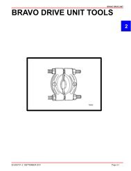
GASOLINE STERNDRIVE INSTALLATION MANUALSpecial ToolsDescriptionPart NumberTransom Drilling Fixture 91-43693A2Engine Alignment Tool 91-805475A1Shift Cable Adjustment Tool 91-12427Engine Mount Drilling Fixture 91-806794A1Tapered Insert Tool 91-43579Shift Shaft Slide Stabilizer Tool 91-809815A1Alpha Notice: Increased Trim-In Range CapabilityThe Alpha trim cylinders provide the capability for an increased trim-in range. A spacer canbe removed from the trim cylinders to increase the trim-in range by approximately 1-1/2degrees. This will improve the acceleration on some boats by forcing the bow down morequickly. If the spacers are to be removed, the boat must be water tested to ensure that theincreased trim-in range does not cause any undesired boat handling characteristics(bow-steer, chine-walk, etc.) if the <strong>sterndrive</strong> is trimmed in while the boat is operated athigher speeds. The boat should be tested under all conceivable load conditions andmaneuvers to ensure that the additional trim-in does not pose a problem. The final decisionand responsibility for use of the additional trim-in range is left up to the boat manufacturer.WARNINGIt is re<strong>com</strong>mended that only qualified personnel adjust the Trim-In Limit Spacer.Boat must be water tested after adjusting or removing the device to ensure that themodified trim-in range does not cause the boat to exhibit an undesirable boat handlingcharacteristic if the <strong>sterndrive</strong> unit is trimmed in at higher speeds. Increasedtrim-in range may cause handling problems on some boats that could result in personalinjury.Page 6 of 137 90-860172011
Bravo Three Notice: Trim-In Limit InsertGASOLINE STERNDRIVE INSTALLATION MANUALNOTE: Bravo One, Two and Three Models are equipped with a Trim-In Limit Insert.It has been brought to our attention that some boats (predominantly deep-Vee heavy boats)will roll up on their side under certain, specific, operating conditions. The roll can be eitherto port or starboard and may be experienced while moving straight ahead, or while makinga turn. The roll occurs most frequently at or near maximum speed, with the <strong>sterndrive</strong> unittrimmed at or near full trim-in. While the boat will not roll <strong>com</strong>pletely over, the roll may besufficient to unseat the operator or passengers, and thereby create an unsafe situation.The roll is caused by stern-lift created from excessive <strong>sterndrive</strong> unit trim-in. Under theseextreme stern-lift / bow-down conditions instability can be created which may cause the boatto roll. Weight distribution to the stern can reduce stern-lift and, in some circumstances, helpto control the condition. Weight distribution in the bow, port or starboard, may worsen thecondition.The Trim-In Limit Insert reduces stern-lift by preventing the <strong>sterndrive</strong> unit from reaching thelast few degrees of full trim under. While this device should reduce the rolling tendency, itmay not eliminate the tendency entirely. The need for this Trim-In Limit Insert, and itseffectiveness, can only be determined through boat testing and is ultimately theresponsibility of the boat manufacturer.Quicksilver ProductsWARNINGIt is re<strong>com</strong>mended that only qualified personnel adjust the Trim-In Limit Insert. Boatmust be water tested after adjusting the device to ensure that the modified trim-inrange does not cause the boat to exhibit an undesirable boat handling characteristicif the <strong>sterndrive</strong> unit is trimmed In at higher speeds. Increased trim-in range maycause handling problems on some boats which could result in personal injury.AccessoriesQuicksilver gauges, remote controls, steering systems, propellers and other accessoriesare available for this product. Mercury MerCruiser re<strong>com</strong>mends the use of Quicksilver partson all applications. Refer to Mercury Precision Parts / Quicksilver Accessories Guide for a<strong>com</strong>plete listing.This Guide is available from:Mercury MarineAttn: Parts DepartmentW6250 W. Pioneer RoadP.O. Box 1939Fond du Lac, WI 54936-1939Outside of U.S.A., order through Distribution Center or Distributor.90-860172011 Page 7 of 137
GASOLINE STERNDRIVE INSTALLATION MANUALSerial Number Decal PlacementThere are three sets of <strong>engine</strong>, transom assembly and <strong>sterndrive</strong> serial number decal stripsprovided with each power package. One should be used for each of the following:• Engine Specification Decal• Warranty Registration Card• Operation, Maintenance and Warranty Manual identification page.Affix serial number decals to specification / serial number decal.Corrosion ProtectionMercury MerCruiser power packages are equipped with anodes to help protect them fromgalvanic corrosion under moderate conditions. However, for severe conditions or if usinga stainless steel propeller, it is re<strong>com</strong>mended that a Quicksilver Anti-Corrosion Anode Kitand/or a MerCathode System be installed (some <strong>models</strong> have a MerCathode System asstandard equipment). A MerCathode Monitor also is available to allow the operator to checkthe operation of the MerCathode System with the push of a button. (Refer to “QuicksilverMercury Precision Parts / Quicksilver Accessories Guide” for part numbers.)Boats which are connected to AC shore power require additional protection to preventdestructive low voltage galvanic currents from passing through the shore power groundwire. A Quicksilver Galvanic Isolator can be installed to block the passage of these currentswhile still providing a path to ground for dangerous fault (shock) currents. (Refer to MercuryPrecision Parts / Quicksilver Accessories Guide for part number.)IMPORTANT: If AC shore power is not isolated from boat ground, the MerCathodeSystem and anodes may be unable to handle the increased galvanic corrosionpotential.Refer to Marine Corrosion Protection Guide P/N 90-881813 01 for specific information aboutmarine corrosion.Page 8 of 137 90-860172011
Anti-fouling PaintGASOLINE STERNDRIVE INSTALLATION MANUALIMPORTANT: Corrosion damage that results from the improper application ofanti-fouling paint will not be covered by the limited warranty.Painting Boat Hull or Boat Transom: Anti-fouling paint may be applied to boat hull andboat transom but you must observe the following precautions:IMPORTANT: DO NOT paint anodes or MerCathode System reference electrode andanode, as this will render them ineffective as galvanic corrosion inhibitors.IMPORTANT: If anti-fouling protection is required for boat hull or boat transom,copper or tin base paints, if not prohibited by law, can be used. If using copper or tinbased anti-fouling paints, observe the following:• Avoid an electrical interconnection between the Mercury MerCruiser Product,Anodic Blocks, or MerCathode System and the paint by allowing a minimum of1-1/2 in. (40 mm) UNPAINTED area on transom of the boat around these items.ab71176a -Painted Boat Transomb-Minimum 1-1/2 in. (40 mm) UNPAINTED Area Around Transom AssemblyNOTE: Sterndrive unit and transom assembly can be painted with a good quality marinepaint or an anti-fouling paint that DOES NOT contain copper, tin, or any other material thatcould conduct electrical current. Do not paint drain holes, anodes, MerCathode system oritems specified by boat manufacturer.90-860172011 Page 9 of 137
GASOLINE STERNDRIVE INSTALLATION MANUALBoat ConstructionTransom Thickness and SurfaceIMPORTANT: Transom thickness and surface plane (flatness) must be controlledwhere the <strong>sterndrive</strong> unit mounts.ThicknessParallelismFlatnessAngleaTransom SpecificationsBetween 2 - 2-1/4 in. (51 - 57 mm) for 8 in. (203 mm) to eitherside of the vertical centerlineInner and outer surfaces must be parallel within 1/8 in. (3 mm)Transom surfaces in area where transom assembly will bemounted (includes vertical as well as horizontal dimensions):Inner Surface – Flat within1/8 in. (3 mm)Outer Surface – Flat within1/16 in. (2 mm)10 -16 Degreesebddc2217072700a -Transom Thicknessb-Inner Surfacec -Outer Surfaced-Transom Plate Coveragee -Transom Angleabc70004a -Measuring Thicknessb-Measuring Flatnessc -Suitable Mandrel To Check For Uniform Transom Thickness75479Page 10 of 137 90-860172011
Engine BedGASOLINE STERNDRIVE INSTALLATION MANUALDifference Between Starboard and Port Engine MountMount Adjustment Up and Down (minimum)22-1/2 in. (572 mm)1/4 in. (6 mm)NOTE: Although the <strong>engine</strong> mounts allow some adjustment, it is a good practice to ensurethat the front and rear mount locations in the vessel are parallel and in the same plane. Thismay be checked by tying a string from the left front mount location to the right rear mountlocation and another from right front to left rear. The strings should touch where they cross.Crankshaft Vertical Centerline1. Locate and mark boat vertical centerline on transom.a71620a -Vertical Centerline2. For Dual Engines: Locate and mark crankshaft vertical centerlines “a” on transom.bacca22033a -Crankshaft Vertical Centerlineb-Minimum Distance Between Crankshaft Vertical Centerlinesc -Crankshaft Vertical Centerlines Must Be An Equal Distance From Boat VerticalCenterlineMinimum Distance Between Crankshaft Vertical Centerlines (Dual Side-By-Side)Modelin. (mm)181 cid / 3.0L 28 (710)262 cid / 4.3L305 cid / 5.0L 33 (838)350 cid / 5.7L90-860172011 Page 11 of 137
GASOLINE STERNDRIVE INSTALLATION MANUALCrankshaft Horizontal Centerline (X-Dimension)90 DEGREE TOOL METHODX-Dimension can be measured by the 90 degree Tool Method or by the Tape MeasureMethod.1. Construct 90 degree tool.a90°b71621a -13-9/16 in. (345 mm)b-Measurement: 4 ft. (1.2 m)To Lower Drive Unit - Subtract from dimension “a.”To Raise Drive Unit - Add to dimension “a.”IMPORTANT: This dimension should only be raised or lowered after proper testing.Single Engine71622Dual Engine716232. Place 90 degree tool along boat bottom at vertical centerline.3. Locate the point at which top of tool contacts transom on vertical centerline. This is thecrankshaft horizontal centerline or X-Dimension.4. Draw a line perpendicular to vertical centerline at crankshaft horizontal centerline.Page 12 of 137 90-860172011
TAPE MEASURE METHODGASOLINE STERNDRIVE INSTALLATION MANUAL1. Determine X-Dimension from the following chart.Transom Angle(degrees)This dimension should only be raised or lowered after propertesting.16 14-5/16 in. (364 mm)15 14-1/4 in. (362 mm)14 14-3/16 in. (360 mm)13 14-1/8 in. (359 mm)12 14-1/16 in. (357 mm)11 14 in. (356 mm)10 13-15/16 in. (354 mm)2. Measure up from the boat bottom the amount shown on the chart for the appropriatetransom angle.7162271623Single EngineDual Engine3. Draw a line perpendicular to vertical centerline at crankshaft horizontal centerline.90-860172011 Page 13 of 137
GASOLINE STERNDRIVE INSTALLATION MANUALTransom CutoutIMPORTANT: The following instructions will provide a <strong>sterndrive</strong> unit mountinglocation that is suitable for most boats. Best mounting location for a particular boat,however, can be determined only by testing.1. Below 25 mph (40 km/h): Subtract 1/2 in. (13 mm) from X-Dimension.2. Heavy Duty Applications: Subtract 1 in. (25 mm) from X-Dimension.3. Above 25 mph (40 km/h): Use X-Dimension shown.4. Above 50 mph (80 km/h): The X-Dimension can be increased to improve performancein some applications. However, pulling power for skiing will decrease. During testing,X-Dimension should be increased 1/2 in. (13 mm) at a time until desired performanceis achieved but in no case should it ever be increased by more than:AlphaBravo One and TwoBravo ThreeMaximum Increase In X-Dimension2-1/2 in. (64 mm)3 in. (76 mm)1 in. (25 mm)Extreme care should be taken when raising drive unit to ensure that water supply does notbe<strong>com</strong>e aerated. Use clear water inlet hose to monitor in<strong>com</strong>ing water and monitor <strong>engine</strong>temperature gauge to ensure <strong>engine</strong> does not overheat.In applications where cooling water to the <strong>engine</strong> is supplied by a through the hullor through the transom fitting, the <strong>sterndrive</strong> height will not cause cooling water aeration.IMPORTANT: Damage to Mercury MerCruiser products caused by too high of aninstalled height will not be covered by Mercury MerCruiser warranty.Page 14 of 137 90-860172011
GASOLINE STERNDRIVE INSTALLATION MANUAL5. Cut out transom using the Template or the Transom Drilling Fixture Kit (purchasedseparately).90-79135--35001722056Transom Cutout Template Transom Drilling Fixture Kit6. Follow instructions indicated on template or provided with drilling fixture.7. Ensure that centerlines on either the template or transom drilling fixture align with linespreviously marked on transom.8. Drill 1/4 in. (6 mm) pilot holes for hole saw guide at a 60 degree angle and cut on theline when making transom cutout. If cutout is made incorrectly, drive unit steering levermay contact transom, thus limiting steering travel.9. Seal inside edge of transom cutout opening with a suitable sealant to prevent waterabsorption and deterioration of transom.10. Cut drain hole and install drain plug flange with appropriate fasteners.90-860172011 Page 15 of 137
GASOLINE STERNDRIVE INSTALLATION MANUALSeawater Connections - General InformationSeawater PickupTHROUGH THE HULL MOUNTEDThis section covers through the hull and through the transom water inlets only. For informationon <strong>sterndrive</strong> water inlet connections, refer to the appropriate section after <strong>engine</strong> <strong>installation</strong>.IMPORTANT: Seal the inside edges of any hole made through the hull with a suitablesealant to prevent water absorption and deterioration.Description Where Used Part NumberA Marine Caulking Mounting Surfaces Obtain Locally1. Seal inside edges of 1-3/4 in. (44 mm) hole in hull using a suitable sealer.2. Apply marine caulking (sealer) to mounting surface on seawater pickup where hullcontact will occur when installed.IMPORTANT: Seawater inlet slots must face forward - parallel with the flow of water.3. Ensure slots in seawater pickup are facing forward (toward bow of boat) and installseawater pickup through hull.4. Fasten pickup with four appropriate mounting screws (if so designed).bdAca72639a -Seawater Pickupb-Seawater Inlet Slotsc -Mounting Screw Holes (If Equipped)d-Nut5. Apply marine caulking as needed inside boat. Apply sealant to threads of nut and installon pickup on inside of boat and torque nut.Description Where Used Part NumberLoctite 271 Seawater Inlet Nut 92-809820Description Nm lb-in. lb-ftNut 42 35NOTE: If pickup being installed does not have mounting screws on underside wheremounted to hull, be certain, after nut is torqued, that slots are still facing forward.Page 16 of 137 90-860172011
TRANSOM MOUNTEDGASOLINE STERNDRIVE INSTALLATION MANUAL1. Seal the inside edges of the 1-1/2 in. (38 mm) hole hose fitting.2. Ensure that the hose fitting and plastic plug are in place and threads have been sealedprior to tightening each securely.Description Where Used Part NumberA Loctite 592 PSTHose Fitting ThreadsPlastic Plug Threads Obtain LocallyB Silicone Sealant Or Equivalent Screw ShaftNOTE: Use a sharp knife or wood chisel to remove excess plastic plug material so that plugis flush with pickup casting.3. Position one flat washer and one rubber O-ring on each 5/16 in. x 4 in. (102 mm) long,round head screw. Coat each screw shaft with sealant.4. Place new gasket on pickup housing and hold pickup in place on transom. Install fourround head screws (with washers and O-rings in place) into pickup mounting holes andthrough drilled 21/64 in. (8 mm) holes in transom.Aacbd e fBAghji72640a -Hose Fittingb-Nut (4)c -Gasketd-O-ring (4)e -Washer (4)f -Screw (4)g-Plastic Pugh-Pickupi -Screenj -Screw (2)90-860172011 Page 17 of 137
GASOLINE STERNDRIVE INSTALLATION MANUALNOTE: Some <strong>installation</strong>s may have 7/32 in. (5 mm) holes drilled in transom using four 5/16in. diameter stainless steel lag bolts in place of round head screws. In any case, flat washersand O-rings are required as outlined.ab72641Water Pickup Installed on Transoma -Diagonal Mount - Leading Edge Of Pickup 1/8 in. (3.2 mm) From Boat Bottom.b-Vertical Mount - Corner Of Leading Edge Of Pickup 1/8 in. (3.2 mm) From BoatBottom5. Secure water pickup from inside with locknuts and washers (unless using lag bolts).6. Tighten fasteners securely.Preliminary ConnectionsPower Trim Pump1. Select an appropriate mounting location for the trim pump that:• Is within length limits of black and gray hydraulic hoses <strong>com</strong>ing from gimbal housingassembly.• Is close to the battery so that trim pump battery leads can be connected.• Allows easy access to trim pump oil fill and vent locations.• Is in an area where pump will not be exposed to water.• Prevents the power steering booster cylinder from <strong>com</strong>ing in contact with the trim pumpwhen the steering wheel is turned in either direction (right or left).NOTE: Template 90-863152 provides mounting hole location for floor or transom mounting.2. Remove the cap plug.3. Mount the pump in the desired location.Page 18 of 137 90-860172011
Fuel Inlet FittingGASOLINE STERNDRIVE INSTALLATION MANUALIMPORTANT: The following information is provided to ensure proper <strong>installation</strong> ofbrass fittings or plugs installed into fuel pump or fuel filter base:• Use #592 Loctite Pipe Sealant with Teflon on threads of fuel inlet fittings or plugs.DO NOT USE TEFLON TAPE.• Fuel inlet fittings or plugs should first be threaded into fuel pump or fuel filterbase until finger tight.• Fuel inlet fittings or plugs should then be tightened an additional 1-3/4 to 2-1/4turns using a wrench. DO NOT OVERTIGHTEN.• To prevent over-tightening when installing a fuel line, the brass fittings should beheld with a suitable wrench as fuel inlet fittings are tightened securely.WARNINGBoating standards (NMMA, ABYC and others) and Coast Guard regulations mustbe adhered to when installing fuel delivery system.WARNINGAvoid <strong>gasoline</strong> fire or explosion. Improper <strong>installation</strong> of brass fittings or plugs intofuel pump or fuel filter base can crack casting and/or cause a fuel leak.1. Remove plastic plug from fuel inlet hole.2. Apply sealant to threads of fuel inlet fitting. DO NOT USE TEFLON TAPE.3. Install fuel inlet fitting. To prevent cracking the casting or causing fuel leaks, turn fuel inletfitting in by hand until finger tight, then tighten connector to 1-3/4 to 2-1/4 turns withwrench. DO NOT overtighten.aAbaA78165771083.0L Model Typical V6 And V8 Modelsa -Fuel Inlet Hose Connects Hereb-Fuel OutletDescription Where Used Part NumberA Loctite 592 Fuel Inlet Fitting Obtain Locally90-860172011 Page 19 of 137
GASOLINE STERNDRIVE INSTALLATION MANUALSPECIAL INFORMATION ABOUT ELECTRIC FUEL PUMPSCAUTIONThe electric fuel pump and factory installed water separating fuel filter have beencarefully designed to function properly together. Do not install additional fuel filtersand/or water separating fuel filters between fuel tank and <strong>engine</strong>.The <strong>installation</strong> of additional filters may cause:• Fuel Vapor Locking• Difficult Warm-Starting• Piston Detonation Due to Lean Fuel Mixture• Poor DriveabilityTransom ConnectionsInstalling Gimbal Housing1. Carefully remove transom assembly from shipping carton.2. Remove and read all tags attached to transom assembly.aba -Dust Coverb-Shipping Hardware220273. Remove the shipping hardware.4. Remove the dust cover if boat will be shipped with drive installed.5. Retain the serial number envelope.Page 20 of 137 90-860172011
Installing Inner Transom PlateGASOLINE STERNDRIVE INSTALLATION MANUAL1. Insert wires, hoses and shift cable through appropriate openings in inner transom plate.2. Position gimbal housing on transom and hold in place.IMPORTANT: Tighten the transom assembly fasteners using an X-pattern torquesequence, starting from the middle fasteners. Tighten in small increments and goaround the pattern several times until the proper torque is achieved.3. Secure transom assembly with hardware as shown. Torque the hardware.Description Nm lb-in. lb-ftTransom Assembly Hardware 31 234. Attach continuity wires.IMPORTANT: Steering lever continuity circuit wire must be positioned as shown toavoid stressing wire when steering lever moves.baaac71626 71628ca7000571627a71629a -Locknuts And Flat Washers (8)b-Torque Sequencec -Continuity Wire90-860172011 Page 21 of 137
GASOLINE STERNDRIVE INSTALLATION MANUAL5. Install the water inlet fitting and j-clip for the gear lube and the speedometer hose.ab77916a -Water Inlet Fittingb-J-clip6. Torque J-clip fasteners.Connecting Speedometer PickupDescription Nm lb-in. lb-ftJ-Clip Fasteners 5 45CAUTIONExcess water in bilge can damage <strong>engine</strong> or cause boat to sink. Do not remove plugfrom speedometer pickup tube fitting unless connection is to be utilized.The connection for the speedometer pickup can be accessed through a hole and fitting inthe inner transom plate.1. Remove plug from speedometer pickup tube fitting.ab70037a -Plugb-Inner Transom Plate FittingPage 22 of 137 90-860172011
GASOLINE STERNDRIVE INSTALLATION MANUAL2. Apply sealant to threads of barb fitting. Install and torque the barb fitting.aA70015a -Barb FittingFluid ConnectionsDescription Where Used Part NumberA Loctite 592 Speedometer Barb Fitting Obtain LocallyDescription Nm lb-in. lb-ftBarb Fitting 1.5 133. Connect a 5/32 in. (4 mm) speedometer hose (not provided) hose from speedometerto barb fitting. Secure hose with cable tie.4. Secure the hose to the transom with the hose clip and screw that are provided in theparts bag.NOTE: The hose must not <strong>com</strong>e into contact with the steering system <strong>com</strong>ponents or the<strong>engine</strong> coupler and drive shaft.1. Connect the gear lube monitor hose to the quick release 90 degree fitting.CAUTIONAvoid <strong>sterndrive</strong> unit damage. Quick release button on gear lube monitor 90 degreehose fitting may not lock on gimbal housing if touching or depressed by water inletfitting or block-off plate, if equipped. Failure to do so could result in a loose 90degree fitting causing a loss of gear lube and damage to drive unit.2. Connect 90 degree fitting to the gimbal housing.ab77916a -Water Inlet Fittingb-90 Degree Fitting90-860172011 Page 23 of 137
GASOLINE STERNDRIVE INSTALLATION MANUALNOTE: The quick release button on hose fitting must be positioned away from water inletfitting, or block-off plate if equipped. Release button must not contact water fitting orblock-off plate, if equipped.NOTE: The hose must not <strong>com</strong>e into contact with the steering system <strong>com</strong>ponents or the<strong>engine</strong> coupler and drive shaft.3. Select a mounting location for coolant recovery bottle and mounting bracket that meetsall of the following:• Within limits of clear plastic tubing.• Level with or above the heat exchanger fill neck.• Accessible for observing coolant level and filling.4. Mount coolant recovery bottle and mounting bracket in desired location using two3/4 in. (19 mm) long screws and flat washers.5. Route plastic tubing to recovery bottle. Ensure that tubing is positioned away from anymoving parts. Cut plastic tubing as required and connect to bottom connection onrecovery bottle and secure with tubing clamp provided.6. Fasten plastic tubing to boat, as necessary, with 2 hose clips and 1/2 in. (13 mm) longscrews (provided).babca -Recovery Bottle And Mounting Bracketb-Screws And Flat Washersc -Plastic Tubingd-Tubing Clampd71712Page 24 of 137 90-860172011
Installing Steering SystemGASOLINE STERNDRIVE INSTALLATION MANUALHYDRAULIC (HELM) STEERINGPOWER STEERINGIf your power package is equipped with Compact Hydraulic Steering, refer to the CompactHydraulic Steering Installation Instructions in the box with the <strong>com</strong>pact hydraulic steering<strong>com</strong>ponents. Complete the <strong>installation</strong> of the hydraulic steering system before proceedingto Transom Preparation.NOTE: For dual <strong>installation</strong>s, power steering unit can be mounted on port or starboardtransom assembly. Measure exact distance between power package centerlines. Select atie bar from Mercury Precision Parts / Quicksilver Accessory Guide. Refer to tie bar<strong>installation</strong> instructions before proceeding.1. Inspect the bushings for debris. Lubricate the bushings.Aab73898a -Bushingsb-Shipping HardwareDescription Where Used Part NumberA Special Lubricant 101 Bushings 92-13872A12. Remove shipping hardware.3. Remove the cotter pins.4. Loosen the upper and lower pivot bolts and ensure that the threads are well lubricated..Add lubricant as necessary.Description Where Used Part NumberSpecial Lubricant 101 Pivot Bolts 92-13872A190-860172011 Page 25 of 137
GASOLINE STERNDRIVE INSTALLATION MANUAL5. Install steering assembly as follows:a. Position steering assembly so that pivot bolts will enter bushings in pivot block orpower steering control valve.b. Install upper and lower pivot bolts along with tab washers. Ensure that tab washertangs straddle the ridge on inner transom plate.c. Turn pivot bolts all the way in by hand to ensure proper alignment.d. Ensure steering assembly pivots freely.6. Torque pivot bolts. Bend tab washer tangs against corresponding flats on bolt heads.cabca -Tab Washersb-Ridgec -Pivot Boltsa7390073899Description Nm lb-in. lb-ftPivot Bolts 34 25NOTE: It may be necessary to tighten further to align flats on pivot bolt with tangs on tabwasher.Page 26 of 137 90-860172011
CAUTIONGASOLINE STERNDRIVE INSTALLATION MANUALMOVING THE CONTROL VALVE RAM with the hoses disconnected will expel fluidfrom the control valve ports. Wear eye protection.7. The control valve ram may be stiff and difficult to move when you attempt to pull it outor push it in for <strong>installation</strong>. Move the assembly in the directions shown below.aa7414574144a -Control Valve Ports8. Connect clevis to steering lever. Lubricate clevis pin. Be sure to spread both ends ofcotter pin.NOTE: Make sure to insert clevis pin from the top to ensure that cotter pin hole is as shownin the diagram.acba -Clevisb-Steering Leverc -Clevis Pind-Cotter Pind71904Description Where Used Part NumberA Special Lubricant 101 Clevis Pin 92-13872A190-860172011 Page 27 of 137
GASOLINE STERNDRIVE INSTALLATION MANUALIMPORTANT: Quicksilver Ride Guide steering cable has a self-locking coupler nutand does not require an external locking sleeve or locking plate.aa -Self-Locking Coupler Nut22060CAUTIONSteering cable outer casing must be free to move back and forth for steering systemto function properly. Do not fasten any items to steering cable.9. Coat steering cable end with a liberal amount of lubricant.10. Install steering cable and secure with hardware.gAefh71906d73901abcd7190371901a -Steering Cableb-Grease Fittingc -Cable Coupler Nutd-Cable Guide Tubee -Steering Cable Endf -Clevisg-Clevis Pinh-Cotter PinDescription Where Used Part NumberA Special Lubricant 101 Steering Cable End 92-13872A1Page 28 of 137 90-860172011
GASOLINE STERNDRIVE INSTALLATION MANUALIMPORTANT: Slight feedback in the steering system could be encountered if thecable guide tube flat surfaces are not positioned vertically.11. Using a suitable wrench hold the flat surfaces on the cable guide tube in the vertical position.Torque coupler nut. Be certain the flat surfaces are still aligned vertically aftertorque is applied to coupler nut.Description Nm lb-in. lb-ftCoupler Nut 47 35CAUTIONSteering cable outer casing must be free to move back and forth for steering systemto function properly. Do not fasten any items to steering cable.90-860172011 Page 29 of 137
GASOLINE STERNDRIVE INSTALLATION MANUALMANUAL STEERING1. Inspect bushings for debris. Lubricate bushings with Special Lubricant 101.aBa22946Manual Steeringa -Bushingsb-Special Lubricant 1012. Remove shipping hardware.3. Remove upper and lower pivot bolts and ensure threads are well lubricated with SpecialLubricant 101.NOTICE to INSTALLERRefer to “Installation Requirements - Steering Helm and Cable” for steering cableselection and coupler nut locking requirements.4. Install steering assembly as follows:a. Position steering assembly so that pivot bolts will enter bushings in pivot block orpower steering control valve.b. Install upper and lower pivot bolts along with tab washers. Ensure that tab washertangs straddle the ridge on inner transom plate.c. Turn pivot bolts all the way in by hand to ensure proper alignment.d. Ensure steering assembly pivots freely.5. Torque pivot bolts to 25 lb-ft (34 Nm). Bend washer tabs against corresponding flats onbolt heads.cba22033Manual Steeringa -Tab Washersb-Ridgec -Pivot BoltsNOTE: It may be necessary to tighten further to align flats on pivot bolt with tabs on tabwasher.Page 30 of 137 90-860172011
CAUTIONGASOLINE STERNDRIVE INSTALLATION MANUALMOVING THE CONTROL VALVE RAM with the hoses disconnected will expel fluidfrom the ports. Wear eye protection.6. The cylinder ram may be stiff and difficult to move when you attempt to pull it out or pushit in for <strong>installation</strong>. First move the spool assembly in the direction(s) shown below.aa74145a -Control Valve Ports74144IMPORTANT: Newer style Quicksilver Ride Guide steering cable has a self-lockingcoupler nut and does not require an external locking sleeve or locking plate.aa -Self-Locking Coupler Nut2206090-860172011 Page 31 of 137
GASOLINE STERNDRIVE INSTALLATION MANUALCAUTIONSteering cable outer casing must be free to move back and forth for steering systemto function properly. Do not fasten any items to steering cable.7. Connect steering cable as follows:a. Remove shipping cap from both ends of steering cable guide tube or control valvespool.b. Coat steering cable end with a liberal amount of Special Lubricant 101.c. Install steering cable and secure with hardware as shown on following pages.NOTICE to INSTALLERRefer to “Installation Requirements - Steering Helm and Cable” for steering cableselection and coupler nut locking requirements.IMPORTANT: Slight feedback in the steering system could be encountered if thecable guide tube flat surfaces are not positioned vertically.ciaebdf50627ghj70018a -Steering Cableb-Grease Fittingc -Cotter Pind-Locking Sleeve (If Required - Must Be Ordered Separately)e -Cable Coupler Nutf -Cable Guide Tubeg-Steering Cable Endh-Cotter Pini -Clevis Pinj -Steering Lever50926Page 32 of 137 90-860172011
GASOLINE STERNDRIVE INSTALLATION MANUALSTEERING HELM AND CABLETransom assembly is shipped with the steering cable guide tube preset for cables with enddimensions that <strong>com</strong>ply with ABYC standards as outlined in the NMMA certificationhandbook. The steering cable coupler nut must also have a means of locking it to the guidetube, as specified in ABYC requirements.WARNINGFailure to use a steering cable locking device could cause loss of steering, whichcould cause damage to the boat and/or injury.NOTE: All current production Quicksilver RideGuide steering cables have a self-lockingcoupler nut and do not require an external locking device. (Other cable manufacturers alsomake cables with self-locking coupler nut.)aa -Quicksilver RideGuide Steering Cable Self-Locking Coupler Nut (Identified ByGroove)22060IMPORTANT: If using a steering cable that does not have a self-locking coupler nut,an external locking device such as a locking sleeve must be used.abExample Of External Locking Devicea -Steering Cableb-Locking SleeveCAUTIONIf steering cable with improper dimensions is installed, severe damage to transomassembly and/or steering system may result.1. Steering cable must be the correct length, particularly when installed in larger boats.2. Avoid sharp bends, kinks or loops in cable.3. Fully extended steering cable end dimension must be as shown.STEERING CABLE SPECIFICATIONSIMPORTANT: Power steering pump lugging (squealing) in a hard right turn (againstlock) may mean a steering cable has been installed that does not have the correctdimensions.90-860172011 Page 33 of 137
GASOLINE STERNDRIVE INSTALLATION MANUALacbefgdCLkljih21435a -Coupler Nut - 7/8 - 14 UNF - 28 Threadb-11-3/4 in. (298 mm) Minimumc -Interface Pointd-1/2 in. (12.7 mm) Maximume -27/64 in. (10.7 mm) Minimum Flatf -7/64 in. (3.1 mm) Minimum Radiusg-5/8 in. (15.9 mm) Maximum Diameter End Fittingh-3/8 in. (9.5 mm)i -3/8 in. (9.8 mm) Diameter Through Hole (Chamfered Each Side)j -1-3/8 in. (34.9 mm) Maxk -5/8 in. (15.9 mm) Diameter Tubel -Cable Travel: Mid-Travel Position - 16-7/8 in. (429 mm)Total Travel To Be 8 in. (203 mm) Minimum to 9 in. (228 mm) MaximumTravel Each Side of Mid-Travel Position - 4 in. (102 mm) Minimum to4-1/2 in. (114 mm) MaximumPage 34 of 137 90-860172011
Transom PreparationGASOLINE STERNDRIVE INSTALLATION MANUALIMPORTANT: Exhaust pipe and gimbal housing mating surfaces must be clean andfree of nicks and scratches and O-ring must be properly seated in groove or waterand exhaust may leak into boat.aba -Gimbal Housing Mating Surfaceb-O-ring220591. Ensure mating surfaces are clean and o-ring is properly seated.2. Loosen hose clamps and remove exhaust pipe and bellows from <strong>engine</strong>.cbbccbadda75819 747683.0L Model V6 and V8 Modelsa -Exhaust Pipeb-Bellowsc -Clampsd-Shipping Plug90-860172011 Page 35 of 137
GASOLINE STERNDRIVE INSTALLATION MANUAL3. Through the Prop Exhaust Models: Install exhaust pipe assembly as shown, usingfour bolts and lockwashers. Torque bolts.ba50684a -Exhaust Pipeb-Bolts And Lockwashers (4)Description Nm lb-in. lb-ftBolts 31 234. Through the Transom Exhaust Models: Install block-off plate as shown, using fourbolts and lockwashers. Torque bolts.aa -Bolts And Lockwashers (4)b-Block-Off Plateb22057Description Nm lb-in. lb-ftBolts 31 23NOTE: Through the Transom exhaust fittings can be installed at this time.Page 36 of 137 90-860172011
GASOLINE STERNDRIVE INSTALLATION MANUAL5. Position rear <strong>engine</strong> mount attaching hardware on inner transom plate mounts asshown.ab50634220543.0L Modelsa -Exhaust Pipeb-Bolts and Lockwashers (4)bac50628a -Fiber Washersb-Double-Wound Lockwashersc -Locknuts90-860172011 Page 37 of 137
GASOLINE STERNDRIVE INSTALLATION MANUALBRAVO MODELSIMPORTANT: When installing through the transom exhaust, it is re<strong>com</strong>mended thatthe exhaust bellows on the transom assembly be removed. This is necessary to avoidcreating a vacuum at the exhaust outlet in the propeller at higher boat speeds. Thisvacuum could degrade propeller performance on some boats.1. If required, remove and discard clamps and bellows from gimbal housing.IMPORTANT: When installing through the propeller exhaust:• With Bravo One and Bravo Two Sterndrives an exhaust tube MAY BE INSTALLEDfor a slight increase in performance.• With most Bravo Three Sterndrive Models an exhaust tube MAY BE INSTALLEDfor a slight increase in performance.• With a Silent Choice Exhaust System the exhaust bellows must be removed andan exhaust tube MUST BE INSTALLED.• With any application, <strong>installation</strong> of an exhaust tube will increase exhaust noise.NOTE: Exhaust tube parts are provided with a Bravo Three Sterndrive. They are locatedin the <strong>sterndrive</strong> unit box.2. If required, install exhaust tube on gimbal housing as follows:a. Remove and discard clamps and exhaust bellows.CAUTIONExhaust tube clamp may corrode if grounding clip is not installed.b. Install grounding clip on tube.NOTE: Bellows adhesive is not used when installing an exhaust tube.c. Position tube so that “SIDE” markings on tube are facing toward the right and leftsides.d. Install and torque the clamp.edcab22184a -Exhaust Tubeb-Clampc -SIDE Markingd-Exhaust Tubee -Grounding ClipDescription Nm lb-in. lb-ftClamp 4 35Page 38 of 137 90-860172011
Driveshaft Extension ModelsGASOLINE STERNDRIVE INSTALLATION MANUALEngine PreparationIf your power package is equipped with a driveshaft extension, refer to the DriveshaftExtension Installation Instructions included with your <strong>engine</strong> package.1. Remove and read all tags attached to <strong>engine</strong>.2. Remove the plug from the <strong>engine</strong> coupler.3. Remove all hardware that secures <strong>engine</strong> to shipping container.4. Connect battery cables to <strong>engine</strong>. Be sure to observe the following:a. Make sure that grounding stud and starter solenoid terminal are free of paint or anyother material that could cause a poor electrical connection.b. After battery cables are connected, apply a thin coat of sealant to the terminals.Description Where Used Part NumberA Liquid Neoprene Battery Terminals 92-25711-2c. Be sure to slide rubber boot over positive (+) terminal after making connection.5. Drape battery cables over top of <strong>engine</strong> to prevent interference during <strong>installation</strong>.IMPORTANT: There is a fuse located at the starter solenoid. DO NOT remove this fuse.The positive battery cable must be connected to the same stud as the fuse.abcd74907a -Positive (+) Battery Cableb-Starter Solenoidc -90 Amp Fuse - DO NOT Removed-Rubber Boot Location6. Remove shipping plug from coupler and lubricate splines.Description Where Used Part NumberA Engine Coupler Spline Grease Coupler Splines 92-816391A47. Install quick oil drain hose plug in oil drain hose.8. Install the fuel inlet fitting.90-860172011 Page 39 of 137
GASOLINE STERNDRIVE INSTALLATION MANUALEngine InstallationNOTE: An <strong>engine</strong> mount drilling fixture (91-806794A1) can be used to align and adjust<strong>engine</strong> mounts. Refer to instructions with fixture for proper use.1. Remove the <strong>engine</strong> cover.2. Attach a suitable sling to lifting eyes on <strong>engine</strong> and adjust so that <strong>engine</strong> is level whensuspended.CAUTIONCenter lifting eye on top of thermostat housing is used for <strong>engine</strong> alignment only.Do not use to lift entire <strong>engine</strong>.abb! CAUTION506363.0L Modelsa -Center Lifting Eyeb-Engine Lifting Eyes5062650632bab! CAUTION 7449874760 74754V6 and V8 Modelsa -Center Lifting Eyeb-Engine Lifting Eyes3. Loosen the <strong>engine</strong> mount adjustment nut.4. Lift <strong>engine</strong> into position in boat using an overhead hoist.Page 40 of 137 90-860172011
GASOLINE STERNDRIVE INSTALLATION MANUAL5. Line up the intermediate elbows with the exhaust tubes.6. Spray lubricant into the exhaust tubes to assist with intermediate elbow <strong>installation</strong> intoexhaust tubes.bbcAca506353.0L Models Typical V6 And V8 Modelsa -Bullhornb-Intermediate Elbowc -Exhaust Tube50682Description Where Used Part NumberA Power Tune Exhaust Tubes 92-802878-577. If equipped with quick drain oil:a. Push end of oil drain hose out of boat hull through flange.b. Pull oil drain hose out until it is 6 in. (152 mm) from the propeller.c. Move alignment clip on the oil drain hose and squeeze to position it on the hose justinside of the boat hull against the flange.d. Connect bilge drain plug to oil drain hose plug using clip.dcba78002a -Oil Drain Hoseb-Alignment Clipc -Clipd-Bilge Drain Plug90-860172011 Page 41 of 137
GASOLINE STERNDRIVE INSTALLATION MANUALe. Push oil drain hose through flange into boat hull.f. Install bilge drain plug in hull.8. Align rear <strong>engine</strong> mounts with inner transom plate mounts while simultaneously aligningexhaust tube with intermediate elbows.9. Install both rear <strong>engine</strong> mounting bolts and hardware and torque. Do not relieve hoisttension.cdeagfa -Rear Engine Mountb-Inner Transom Plate Mountc -Boltd-Washere -Spacerf -Fiber Washerg-Double-Wound Lockwasherb72535Description Nm lb-in. lb-ftRear Engine Mounting Bolts 51 38IMPORTANT: If quick drain oil fitting is within 1/2 in. (6 mm) of boat bottom, removefitting and install drain plug from parts bag directly into oil pan.10. Ensure quick drain oil fitting is more than 1/2 in. (6 mm) above the boat bottom.Page 42 of 137 90-860172011
Exhaust SystemGASOLINE STERNDRIVE INSTALLATION MANUALMEASURING PROCEDURECAUTIONIt is the responsibility of the boat manufacturer or installing dealer to properly locatethe <strong>engine</strong> and install the exhaust system. Improper <strong>installation</strong> may allow waterto enter the exhaust manifolds and <strong>com</strong>bustion chambers and severely damagethe <strong>engine</strong>. Damaged caused by the water in the <strong>engine</strong> will not be covered by MercuryMerCruiser Warranty, unless this damage is the result of defective parts.1. Fill all fuel, water, gray water and heater tanks to maximum capacity.NOTE: Weight can be added in these locations to simulate full loaded condition.2. Add maximum allowable cargo weight to boat in areas where it will be stowed, includingrefrigerator and lockers.3. Add 190 lb (86 kg) of weight in all locations where each passenger will sit during normaloperation.4. Measure exhaust elbow height. Also, measure exhaust system slope on applicationswith through the hull or through the transom exhaust.abUsing A Universal Protractor (Inclinometer) To Measure Slopea -Protractorb-Exhaust Hose Or Tube7798190-860172011 Page 43 of 137
GASOLINE STERNDRIVE INSTALLATION MANUAL5. On applications with through the propeller exhaust: Proceed to Step 7.6. On applications with through the hull or through the transom exhaust:a. Move load weight to bow to simulate greatest bow-down attitude the boat willencounter in normal operation.b. Recheck exhaust system slope.7. Move load weight and cargo weight to stern of boat to stimulate greatest stern-downattitude the boat will encounter such as when loading.IMPORTANT: Be sure to consider swim platform loading and personal watercraft.8. Recheck exhaust system measurements.Minimum Exhaust Elbow Height from Top of Elbow to WaterlineModelMeasurementAll V6 and V813 in. (330 mm)ab13 [330] cd70082a -Top Of Transomb-Highest Point On Exhaust Elbowc -Measurementd-Waterline77956Additional requirements for through the hull or transom exhaust system applications:Minimum Continuous Downward Slope (Exhaust Hoses, Collector, Etc.)ModelMeasurement (degrees)All Sterndrive 6Page 44 of 137 90-860172011
GASOLINE STERNDRIVE INSTALLATION MANUAL9. If measurements are less than specified, exhaust elbow risers must be installed toachieve proper dimension.abcdeTypical Riser Installationa -Exhaust Elbowb-Restrictor Gasketc -Riserd-Open Gasket (4 Slots)e -Exhaust ManifoldNOTE: Up to a maximum of 9 in. (229 mm) of riser height can be added.7799190-860172011 Page 45 of 137
GASOLINE STERNDRIVE INSTALLATION MANUALMethods for Measuring Exhaust Elbow HeightSTRAIGHT EDGE METHOD1. Place a straight edge across boat.2. With the straight edge above the <strong>engine</strong> as shown, measure the distance between thestraight edge and the top of the exhaust elbow.3. Make sure that the boat is level from side-to-side, using a level or inclinometer. Then,measure the distance between the straight edge and the outside waterline.4. The difference between these two measurements is the exhaust elbow height above thewater line. Refer to Measuring Procedures and <strong>com</strong>pare measurement tospecifications.cbdae76859a -Waterlineb-Top Of Exhaust Elbowc -Straight Edged-Measurement Between Straight Edge And Top Of Exhaust Elbowe -Measurement Between Straight Edge And Water Line72700Page 46 of 137 90-860172011
CLEAR HOSE METHODGASOLINE STERNDRIVE INSTALLATION MANUAL1. Obtain a 5/16 - 3/8 in. (8-10 mm) long hose approximately 15 ft. (4.5 m) long. Put a metalfitting or a weight on one end of the hose to keep that end of the hose below the waterline.2. Put the weighted end of the hose over the port or starboard side of the boat, keepingit in line with the <strong>engine</strong>’s exhaust elbow.3. Route the remainder of the hose toward the <strong>engine</strong>’s exhaust manifold and elbow.Ensure that this open end section of the hose is as vertical as possible from the boat’sbilge to the top of the exhaust elbow4. Coil excess hose in bilge of boat, keeping it below the water line.5. Lower open end of hose and siphon water until it starts to <strong>com</strong>e out of the hose. Put afinger over the hose and lift open end until it is at the top of the exhaust elbow.6. Slowly take finger off end of hose to let the water level stabilize. The water will seek thelevel of the water outside the boat. Keep hose close to exhaust elbow and as verticalas possible.7. Make sure that the boat is level (side-to-side) using a level or inclinometer.8. The measurement between water in hose and top of exhaust elbow is the exhaust elbowheight.bcae76859ada -Waterlineb-Top Of Exhaust Elbowc -Clear Plastic Hosed-Weighte -Measurement - Waterline To Top Of Exhaust Elbow7270090-860172011 Page 47 of 137
GASOLINE STERNDRIVE INSTALLATION MANUALExhaust System Hose / Tube ConnectionsCAUTIONAvoid exhaust hose failure. Discharge water from exhaust elbow must flow aroundentire inside diameter of hose to avoid causing hot spots which could eventuallyresult in burned-through exhaust hoses. Exhaust hoses and/or tubes must be correctlyconnected to exhaust elbows so that they do not restrict the flow of dischargewater from exhaust elbow.71653Correct ConnectionIncorrect ConnectionIMPORTANT: Exhaust hoses/tubes should be secured at each connection with atleast 2 hose clamps.1. Tighten all exhaust hose and/or exhaust tube clamps securely.aa -Hose Clamps73961Page 48 of 137 90-860172011
Engine AlignmentGASOLINE STERNDRIVE INSTALLATION MANUAL1. Ensure that the dust cover is removed or folded back out of the way.a22027a -Dust CoverCAUTIONDO NOT use an alignment tool from another manufacturer. Alignment tools otherthan Quicksilver Alignment Tool may cause improper alignment and damage togimbal bearing and/or <strong>engine</strong> coupler.2. Attempt to insert the solid end of the alignment tool through the gimbal bearing and intothe <strong>engine</strong> coupler splines.3. If the tool does not fit, remove it and carefully raise or lower the front end of the <strong>engine</strong>using the center alignment eye and attempt to insert the alignment tool.90-860172011 Page 49 of 137
GASOLINE STERNDRIVE INSTALLATION MANUAL4. Repeat step 3. until the alignment tool installs easily (SLIDES FREELY WITH TWOFINGERS) all the way into and out of <strong>engine</strong> coupler splines. Do not check by turningthe alignment tool.baa -Alignment Tool (Use Only Re<strong>com</strong>mended Alignment Tool)b-Insert This End Of Alignment Tool Through Gimbal Housing Assembly22029cba27647a -Alignment Toolb-Gimbal Bearingc -Engine CouplerPage 50 of 137 90-860172011
GASOLINE STERNDRIVE INSTALLATION MANUALIMPORTANT: Finished boat stringer must position <strong>engine</strong> so that a minimum mountadjustment exists after front mount is adjusted down to stringer. This allows forfuture adjustments.5. 3.0L Center Mount Model:a. Set the <strong>engine</strong> on the stringer.b. Relieve the hoist tension.c. Attach the hoist to the center alignment eye.d. Fasten front mount to the stringer.e. Recheck alignment.f. Tighten locknut and jam nut securely.cabedb3.0L Center Mount Modela -Front Mountb-Attaching Bolts and Flat Washersc -Adjusting Nutd-Locknute -Jam Nut2205490-860172011 Page 51 of 137
GASOLINE STERNDRIVE INSTALLATION MANUALIMPORTANT: Turn both front <strong>engine</strong> mount adjustment nuts an equal amount indirection required to align <strong>engine</strong>.6. All Other Models:a. Adjust front <strong>engine</strong> mounts until they rest on boat stringers.b. Relieve hoist tension entirely and fasten both front mounts to boat stringer using appropriatehardware.c. Tighten the bottom nut to hold the <strong>engine</strong> in place. Then release the tension.bcada3.0L Side Mount Modela -Engine Mountb-Boltc -Lockwasherd-Tab Washer7796877970bac77913V6 and V8 Modelsa -Engine Mountb-Bottom Nut - Not Visiblec -TabPage 52 of 137 90-860172011
GASOLINE STERNDRIVE INSTALLATION MANUAL7. Recheck alignment with alignment tool. Tool must enter coupling splines freely. If not,readjust front mounts.8. When alignment is correct, tighten locknut securely. Recheck alignment.9. Bend tab down on adjusting nut.10. Remove alignment tool. If not installing drive, fold bell housing dust cover flap back intoplace and tape shut for boat shipment. Dust cover flap will have to be removed beforeoperating <strong>engine</strong>.11. Hook up the ground stud.12. Connect the trim pump sender wires.13. Install the water inlet hose onto the transom.Hot Water Heater InstallationSUPPLY HOSE CONNECTIONIMPORTANT: When connecting a cabin heater or hot water heater:• Supply hose (from <strong>engine</strong> to heater) and return hose (from heater to <strong>engine</strong>)MUST NOT EXCEED 5/8 in. (16 mm) inside diameter (ID).• Make heater connections ONLY at locations shown.• Refer to manufacturers’ instructions for <strong>com</strong>plete <strong>installation</strong> information andprocedures.• Do not reposition <strong>engine</strong> temperature switch.CAUTIONAvoid a performance loss and/or possible <strong>engine</strong> damage. Engine coolant mustflow continuously from the <strong>engine</strong> intake manifold to the <strong>engine</strong> water circulatingpump. NEVER close-off or block the coolant flow to or from a heater.CAUTIONAvoid <strong>engine</strong> overheating which could result in <strong>engine</strong> damage. On <strong>models</strong>equipped with Closed Cooling, an air pocket may form in the closed cooling systemif some coolant is lost from the system and the cabin heater or hot water is mountedhigher than the fill cap on the heat exchanger. Heater must be mounted lower thanthe fill cap of the heat exchanger on <strong>models</strong> so equipped.a760953.0La -Location For Hot Water Supply (Install Bayonet Fitting Here)90-860172011 Page 53 of 137
GASOLINE STERNDRIVE INSTALLATION MANUALaa7547374973Seawater Cooling - If Location Is Availablea -Location For Hot Water Supplya71758Seawater Cooling - Alternate Locationa -Location For Hot Water Supplybaab74639Closed Cooling Models - If Location Is Availablea -Location for Hot Water Supply (Bayonet Fitting Replaces Brass Plug)b-Thermostat HousingPage 54 of 137 90-860172011
GASOLINE STERNDRIVE INSTALLATION MANUALRETURN HOSE CONNECTIONa73572Typical 3.0La -Location For Hot Water Return (T-Fitting Installed in Water Circulating PumpHose)aSeawater or Closed Cooling Systema -Location For Hot Water ReturnElectrical ConnectionsInstalling Continuity Wire75480IMPORTANT: When routing all wire harnesses and hoses, be sure they are routed andsecured to avoid <strong>com</strong>ing in contact with hot spots on <strong>engine</strong> and to avoid contactwith moving parts.1. Connect continuity circuit wire from <strong>engine</strong> to transom assembly.IMPORTANT: Do not attach any accessory ground (–) wires to transom plate groundpoint. Accessory ground wires can only be attached to ground stud on <strong>engine</strong>.a -Continuity Wirea7165190-860172011 Page 55 of 137
GASOLINE STERNDRIVE INSTALLATION MANUALInstrumentation ConnectionsWe re<strong>com</strong>mend the use of Quicksilver Instrumentation and Wiring Harnesses. On dual stationapplications, oil pressure and water temperature senders (on <strong>engine</strong>) must be changed.Refer to Mercury Precision Parts / Quicksilver Accessories Guide for selection.The 4 basic gauges that must be used with the <strong>engine</strong> are:• Tachometer• Oil Pressure• Water Temperature• VoltmeterIMPORTANT: Connect fused accessory panel (40-amp current draw maximum) mustbe connected as shown in the wiring diagrams.1. Route instrumentation wiring harness back to <strong>engine</strong>, making sure that harness doesnot rub or get pinched. If an extension harness is required, be sure to secure connectionproperly.2. Fasten harnesses to boat at least every 18 in. (460 mm), using appropriate fasteners.3. Place hose clamp over instrumentation wiring harness.4. Connect the instrumentation wiring harness to <strong>engine</strong> harness plug at location shown.aTypicala -Wiring Harness Connector5. Tighten hose clamp to secure wiring harness to <strong>engine</strong> harness plug.74754Page 56 of 137 90-860172011
Trim Position Sender ConnectionsGASOLINE STERNDRIVE INSTALLATION MANUAL1. Connect trim position sender wires (from transom assembly) to <strong>engine</strong> harness.abaORG/WHTBLKBLKBLKb74029a -Engine Harness Bullet Connectorb-Transom Assembly Bullet ConnectorMerCathode Connections (If Equipped)1. Connect wires to MerCathode controller assembly as shown. Apply a thin coat of LiquidNeoprene to all connections.IMPORTANT: Opposite end of RED/PURPLE wire must be connected directly tobattery positive (+) terminal. DO NOT connect it to a switched positive (+) circuit.MerCathode system must function continuously for proper corrosion protection.a b c da -ORANGE Lead - From Electrode On Transom Assemblyb-RED/PURPLE Wire - To Positive (+) Battery Terminalc -BLACK Wire - From Engine Harnessd-BROWN Wire - From Electrode On Transom Assembly22232Description Where Used Part NumberA Liquid Neoprene MerCathode Connections 92-25711-290-860172011 Page 57 of 137
GASOLINE STERNDRIVE INSTALLATION MANUALAudio Warning System ConnectionsWARNINGAlarm is not external ignition-proof, therefore, DO NOT mount alarm in <strong>engine</strong> orfuel tank <strong>com</strong>partments.1. Select a location for audio warning alarm which meets all of the following:• alarm can be easily heard, yet is out of sight• alarm can be easily accessed for <strong>installation</strong> and maintenance• alarm will remain dry• alarm is within length limits of the 18 in. purple alarm wire that connects to the “I” terminalor 12 volt source on switched side of ignition switch.NOTE: The terminal to which wire is attached must have no voltage when ignition switchis in the OFF position.2. Place alarm in desired location and secure to wire bundle with tie-strap provided.3. Connect PURPLE wire from alarm to any PURPLE wire terminal on instrument gaugeor ignition switch. Tighten connection securely.4. Connect TAN/BLUE wire from alarm to TAN/ BLUE wire from instrument harness.5. Place the small (transparent) decals on the bottom of the water temperature and the oilpressure gauges.6. Place the large decal on the instrument panel or other appropriate location in easilyviewed by the operator.ALARM INDICATES LOWOIL OR OVERHEATINGaAPPLY THE PROPER DECAL TO THE DASHBOARDOR OTHER APPROPRIATE LOCATION:bAUDIO WARNING HORN WILL SOUND WHEN:1. ENGINE OIL PRESSURE IS TOO LOW2. ENGINE TEMP. IS TOO HIGH, OR3. DRIVE OIL LEVEL IS TOO LOWTO TEST AUDIO WARNING HORN:TURN KEY TO “ON” POSITION (ENGINE OFF)75430a -Small Decal (Transparent)b-Larger Decal7. Test audio warning system during Predelivery Preparation section.Page 58 of 137 90-860172011
Power Trim Pump ConnectionsGASOLINE STERNDRIVE INSTALLATION MANUALIMPORTANT: Make hydraulic connections as quickly as possible to prevent oil fromleaking out of system. Be careful not to cross-thread or overtighten hose fittings.1. Connect hydraulic hoses to trim pump. Torque fittings.Description Nm lb-in. lb-ftFittings 14 1252. Connect power trim pump control harness to trim pump.3. Connect trim limit switch wires and secure with wire retainer and tie-strap.dc7512675127bafg50630e50632a -Black Hose Fitting (UP Circuit)b-Gray Hose Fitting (DOWN Circuit)c -Control Harnessd-Tie-Strape -Trim Limit Switch Wire (With Blue Sleeve) To BLUE/WHITE Harness Wiref -Trim Limit Switch Wire (With Purple Sleeve) To PURPLE/WHITE Harness Wireg-Wire Retainer And Tie Strap90-860172011 Page 59 of 137
GASOLINE STERNDRIVE INSTALLATION MANUAL4. Unscrew fill cap and remove cap plug from fill neck and discard. Install fill cap.aba -Caplugb-Fill Cap506305. Connect power trim pump wires to battery.aba -Positive Battery Leadb-Negative Battery Lead76631Page 60 of 137 90-860172011
Fluid ConnectionsGASOLINE STERNDRIVE INSTALLATION MANUALGear Lube Monitor HoseIMPORTANT: Avoid using excessive hose when routing it to gear lube monitor. Hoseshould be routed directly to oil reservoir in as straight a line as possible to avoid lowspots (traps) in the system.CAUTIONEnsure hose is not kinked when connecting in the following step. If hose is kinked,gear lube monitor will not function properly and damage to drive unit could occur.1. Route hose to gear lube monitor and cut off excess hose. Hose can be routed on outsideof remote oil filter or the hole in the front lifting eye bracket.2. Connect hose and secure with hose clamp.IMPORTANT: Hose must not <strong>com</strong>e in contact with steering system <strong>com</strong>ponents or the<strong>engine</strong> coupler, U-joint shaft or drive shaft.abac71983d77108181 CID/3.0L Model Typicala -Gear Lube Monitorb-Hosec -Clampd-Sta-Strap3. Use extra hose clips to secure hose to transom.90-860172011 Page 61 of 137
GASOLINE STERNDRIVE INSTALLATION MANUALPower Steering HosesCAUTIONRoute hoses exactly as shown below. This will help avoid stress on the hose fittingsand will help avoid kinks in the hose.IMPORTANT: Make hydraulic connections as quickly as possible to prevent fluidleakage.IMPORTANT: Be careful not to cross-thread or overtighten fittings.1. Route hoses. Secure hoses to avoid contact with moving <strong>com</strong>ponents.2. Connect power steering hoses to control valve. Torque both fittings.Description Nm lb-in. lb-ftFittings 31 233. Use extra hose clips to secure hose to transom.NOTE: Power Steering Fluid can be added at this point, if desired.Bravo Models and Alpha Seawater Cooled Models Using Sterndrive WaterPickups1. Connect water hose to water inlet fitting.2. Secure with hose clamp.bca72040a -Water Inlet Fittingb-Hosec -Hose ClampPage 62 of 137 90-860172011
Alpha or Bravo Models Using Alternative Water PickupsGASOLINE STERNDRIVE INSTALLATION MANUALA water inlet block-off kit must be used if the <strong>sterndrive</strong> unit water pickup will not be usedto supply water to the <strong>engine</strong>. When installing the block-off plate, it is necessary to cut thewater hose that is located between the bell housing and the gimbal housing. This allowswater to continue to circulate through the <strong>sterndrive</strong> unit for cooling.CAUTIONAvoid overheating <strong>sterndrive</strong>. The seawater inlet holes must be allowed to flowwater without being obstructed or overheating damage to <strong>sterndrive</strong> may result. Donot dead-end seawater hose from bell housing. Cut hose as re<strong>com</strong>mended inprocedures.1. Remove the existing water fitting and gasket. Discard the screws and washers.ab50663a -Water Fittingb-Screws And Lockwashers2. Remove the tapered insert in the gimbal housing using the tapered insert tool(91-43579). Discard the insert.acaba -Tapered Insertb-Tapered Insert Toolc -Gimbal Housing Cross-Sectional View2208022101DescriptionPart NumberTapered Insert Tool 91-4357990-860172011 Page 63 of 137
GASOLINE STERNDRIVE INSTALLATION MANUAL3. Install the block-off plate with new gasket. Secure with screws and lockwashers. Torquethe screws.acd b75314a -Block-Off Plateb-Gasketc -Screwd-LockwasherDescription Nm lb-in. lb-ft1 Screw, Water Fitting 5 45753134. Move the trim limit switch wires and speedometer hose aside. Reach between thegimbal housing and the bell housing and detach the water hose from the gimbal housingwhere the tapered insert was removed in Step 2.adecb71184a -Trim Limit Switch Wiresb-Speedometer Hosec -Gimbal Housingd-Water Hosee -Tapered Insert22101Page 64 of 137 90-860172011
WARNINGGASOLINE STERNDRIVE INSTALLATION MANUALAvoid water leakage into boat. Damage to U-joint bellows could result in waterentering the boat. Do not damage the U-joint bellows when removing a section ofthe water hose attached between the gimbal housing and bell housing.NOTE: Move the trim limit switch wires and speedometer hose to avoid damaging themwhen cutting the water hose. The existing tie strap and clip can be reused if they are movedand repositioned after the hose is cut.5. Cut <strong>com</strong>pletely through the water hose 5 in. (127 mm) in front of the aft end of the hosewhere it is fitted into the bell housing. in the area shown. DO NOT damage the U-jointbellows. Discard loose hose piece.6. Secure the trim limit switch wires and speedometer hose to the remaining section ofwater hose using existing tie strap and clip.cefbda71184a -Tie Strapb-Clipc -Water Inlet Hosed-Speedometer Hosee -Trim Limit Wire Harnessf -Cutting Area90-860172011 Page 65 of 137
GASOLINE STERNDRIVE INSTALLATION MANUALCoolant Recovery SystemCAUTIONAvoid <strong>engine</strong> overheating and subsequent damage to <strong>engine</strong>. The coolant recoverysystem will not operate properly without proper sealing. Plastic tubing MUST seal<strong>com</strong>pletely at connections.1. Connect plastic tubing to bayonet fitting on heat exchanger. Secure with tubing clampprovided.ba70548a -Plastic Tubingb-Tubing Clamp1. Remove cap from coolant recovery reservoir and fill to FULL mark with coolant solution.2. Reinstall cap.Page 66 of 137 90-860172011
Shift Cable InstallationGASOLINE STERNDRIVE INSTALLATION MANUALAlpha Models - Drive Unit Not InstalledWe re<strong>com</strong>mend the use of a Quicksilver remote control and cable. Refer to MercuryPrecision Parts / Quicksilver Accessories Guide for selection. However, if a control otherthan Quicksilver is to be used, control must provide a shift cable travel (at the shift plate end)of 2-7/8 in. (73 mm) to 3-1/8 in. (80 mm) with a 15-20 lb. (6.8-9 kg) load applied to the cableend guide.NOTE: On <strong>engine</strong>s with Alpha drives, the measurement indicated above can be taken byinstalling the remote control shift cable and using the shift assist assembly (provided) toplace the proper load on the shift cable.1. Place a mark on the tube against the edge of the cable end guide.deabc50368a -Shift Assist Assemblyb-Remote Control Shift Cable - In FORWARD Gear Positionc -Edge Of Cable End Guided-Remote Control Shift Cable - In REVERSE Gear Positione -Measurement Taken From Mark To Edge Of Cable End Guide:2-7/8 in. (73 mm) to 3-1/8 in. (80 mm)a90-860172011 Page 67 of 137
GASOLINE STERNDRIVE INSTALLATION MANUALIMPORTANT: If boat is being equipped with a REMOTE CONTROL THAT HASSEPARATE SHIFT AND THROTTLE LEVERS, the shift assist assembly that is shippedwith the <strong>engine</strong> should NOT be used. The use of the shift assist assembly with thistype of remote control can cause the shift lever to move out of gear unexpectedly.The following kit will have to be ordered to connect remote control shift cable when shiftassist assembly is not used.Spacer Kit 23-11284A1daba -Clevis Pinb-Washerc -Spacerd-Cotter Pinc50310NOTE: Do not discard shift assist assembly until after it is used in step 3., following.IMPORTANT: Shift cable must be connected at the remote control for the appropriaterotation (LH or RH) drive unit, as explained following:RIGHT HAND ROTATION - Control cable will have to be installed in remote control so thatcable end will move in direction “A” when shift handle is placed in the FORWARD position.LEFT HAND ROTATION - Control cable will have to be installed in remote control so thatcable end will move in direction “B” when shift handle is placed in the FORWARD position.AB71656Page 68 of 137 90-860172011
GASOLINE STERNDRIVE INSTALLATION MANUALIMPORTANT: Use the following procedure to temporarily install shift cables if boatwill be shipped without drive unit installed. Refer to Shift Cable Installation for shiftcable adjustment procedure once drive unit is installed.1. Remove shift cable attaching hardware.cba -Cotter Pinb-Clevis Pin And Cotter Pinc -Washer And Locknuta503082. Place remote control shift lever in NEUTRAL position.3. Temporarily install clevis pin through remote control shift cable end guide, shift assistassembly end and into hole in shift lever. Then adjust brass barrel so that hole in barrelaligns with anchor stud.caa -Clevis Pinb-Shift Cable End Guidec -Shift Assist Assembly Endd-Shift Levere -Brass Barrel (On Stud)dbe5030890-860172011 Page 69 of 137
GASOLINE STERNDRIVE INSTALLATION MANUAL4. Remove remote control shift cable and shift assist assembly.IMPORTANT: Install the cotter pin through the top of the barrel retainer.5. Install drive unit shift cable as shown. Secure brass barrel in barrel retainer with cotterpin and spread both prongs. Secure cable end guide with washers (one on each sideof end guide) and locknut. Tighten locknut until it contacts, then loosen 1/2 turn.Without Shift Assist Assemblya -Cotter Pinb-Locknut And Washersba75415Page 70 of 137 90-860172011
GASOLINE STERNDRIVE INSTALLATION MANUAL6. Install remote control shift cable (with or without shift assist assembly as applicable) andsecure with hardware as shown. Tighten locknut finger tight only and do not spreadcotter pin <strong>com</strong>pletely. (Remote control shift cable fasteners will have to be removedagain to properly adjust shift cables under Shift Cable Installation section of this<strong>manual</strong>.)adbec50308With Shift Assist Assemblya -Remote Control Shift Cableb-Shift Assist Assemblyc -Clevis Pin And Cotter Pind-Large I.D. Washere -Small I.D. Washer And LocknutcadbeWithout Shift Assist Assemblya -Remote Control Shift Cableb-Pinc -Cotter Pin (Existing)d-Spring (Existing)e -Washer (Existing)f -Washerg-Spacerh-Washer (Existing)i -Locknut (Existing)ghif5031090-860172011 Page 71 of 137
GASOLINE STERNDRIVE INSTALLATION MANUALBravo ModelsNOTE: Using Adjustment Tool (91-12427), shift cables can be adjusted without or with the<strong>sterndrive</strong> installed, using the following procedure.IMPORTANT: Sterndrive unit propeller rotation is determined by the shift cable<strong>installation</strong> in the remote control.• Bravo One/Two - If shift cable end guide moves in direction A when control leveris placed in FORWARD, remote control is set up for RIGHT HAND (RH) propellerrotation.• Bravo One/Two - If shift cable end guide moves in direction B when control leveris placed in FORWARD, remote control is set up for LEFT HAND (LH) propellerrotation.AB71656Arrow Indicates Direction Of Motion• Bravo Three - Front propeller on <strong>sterndrive</strong> unit is always LH Rotation and rearpropeller is always RH Rotation. Shift cable end guide must move in direction A,when control lever is placed in FORWARD gear position.A71656IMPORTANT: When installing shift cables, be sure that cables are routed in such away as to avoid sharp bends and/or contact with moving parts. DO NOT fasten anyitems to shift cables.1. Install shift cable into remote control. (Refer to appropriate remote control instructions.)2. Remove the guide.3. Loosen stud and move it to dimension, as shown. Retighten stud.ba71657a -Studb-3 in. (76 mm) (Center Of Pivot Bolt To Center Of Stud)Page 72 of 137 90-860172011
4. Install <strong>sterndrive</strong> unit shift cable.5. Tighten locknut until it contacts and then loosen 1/2 turn.6. Insert cotter pin from top and spread ends.GASOLINE STERNDRIVE INSTALLATION MANUALabc71658a -Washers (2)b-Locknutc -Cotter Pin7. Place adjustment tool over <strong>sterndrive</strong> unit shift cable, as shown. Hold tool in place, usinga piece of tape over the barrel retainer.716598. Locate center of remote control and control cable play (backlash).IMPORTANT: Be sure to keep center mark “c” aligned with control cable end guideedge when making the following adjustment.a. Shift remote control to NEUTRAL.b. Push in on control cable end with enough pressure to remove play and mark position“a” on tube.c. Pull out on control cable end with enough pressure to remove play and mark position“b” on tube.d. Measure distance between marks “a” and “b” and mark position “c” half-waybetween marks “a” and “b.”cab7165690-860172011 Page 73 of 137
GASOLINE STERNDRIVE INSTALLATION MANUAL9. Temporarily install control cable end guide into shift lever and insert anchor pin.10. Adjust control cable barrel so that hole in barrel centers with vertical centerline of stud.Ensure that backlash center mark is aligned with edge of control cable end guide.CAUTIONDO NOT attempt to install or remove control cable barrel from stud without first removingend guide anchor pin from shift lever and removing cable. Attempting tobend control cable to install or remove barrel will place undue stress on cable endguide and shift lever and damage to both could occur.11. Remove control cable end guide from shift lever by removing anchor pin.bacde71660a -Control Cable End Guideb-Anchor Pinc -Backlash Centerd-Control Cable Barrele -Stud12. Install control cable.13. Install washer and locknut.14. Tighten locknut until it contacts and then loosen 1/2 turn.15. Insert cotter pin from top and spread ends.cba71661a -Locknutb-Washers - Both Sides Of Barrelc -Anchor Pind-Cotter Pin (Not Shown)Page 74 of 137 90-860172011
GASOLINE STERNDRIVE INSTALLATION MANUAL16. Remove adjustment tool.17. Shift remote control lever into full FORWARD position. Place end of adjustment tool inbarrel retainer.RH rotation Bravo One, Two and Three Models: Rear slot in tool should fit over shift leverstud.LH rotation Bravo One And Two: Forward slot in tool should fit over shift lever stud.If slot does not fit over stud, loosen shift lever stud and slide stud up or down until slot in toolfits over stud. When adjustment is correct, retighten stud.cab71662RH Rotation Bravo One, Two, Threedcab71663LH Rotation Bravo One And Twoa -Adjustment Toolb-Barrel Retainerc -Shift Lever Studd-Shift Lever Adjustment Slot18. Remove adjustment tool.19. Lubricate shift cable pivot points.Description Where Used Part NumberSAE 30W Engine Oil Shift Cable Pivot Points Obtain Locally90-860172011 Page 75 of 137
GASOLINE STERNDRIVE INSTALLATION MANUALThrottle Cable Installation and Adjustment1. Place remote control handle(s) in neutral/idle position.IMPORTANT: Be sure that cable is routed to avoid sharp bends and/or contact withmoving parts. DO NOT fasten any items to throttle cable. Outer cable must be free tomove when cable is actuated.2. Adjust cable so that it can be placed on both studs simultaneously.3. Place cable over studs. DO NOT adjust cable after <strong>installation</strong>.4. Secure throttle cable with hardware as shown. DO NOT overtighten as cable must pivotfreely. Tighten until nut contacts, then loosen 1/2 turn.5. Place remote control throttle lever in the wide open throttle (WOT) position. Ensure thatthrottle shutters are <strong>com</strong>pletely open.6. Return remote control throttle lever to idle position and ensure that throttle lever contactsidle speed adjustment screw.gedhcbfaij769002 BBL V6 and V8 Modelsa -Cable End Guideb-Throttle Lever Screwc -Locknut and Flat Washer (Small)d-Throttle Levere -Idle Speed Adjustment Screwf -Idle Camg-Throttle Bracketh-Cable Barreli -Flat Washer and Locknut (Large)j -Throttle Cable Anchor StudPage 76 of 137 90-860172011
Sterndrive Unit InstallationGASOLINE STERNDRIVE INSTALLATION MANUAL1. Remove trim cylinder support and dust cover from bell housing studs. (Retain elasticstop nuts and flat washers.)2. Remove gear lube monitor cap. Fill with lubricant.a77108a -Gear Lube MonitorDescription Where Used Part NumberA High Performance Gear Lube Gear Lube Monitor 92-802853A13. Push dribble valve stem in until gear lube appears.aa -Dribble Valve Stem755314. Once gear lube appears, release dribble valve stem.5. Fill monitor to FULL mark.6. Replace monitor cap.90-860172011 Page 77 of 137
GASOLINE STERNDRIVE INSTALLATION MANUALIMPORTANT: Rubber gasket must be properly positioned in bell housing bore beforeinstalling drive unit or water may leak into boat.7. Alpha Models: Ensure that rubber gasket and water passage O-ring are properlypositioned in bell housing.ab75531a -Rubber Gasketb-Water Passage O-ring8. Coat <strong>sterndrive</strong> unit pilot, U-joint O-rings and drive shaft splines.AabbAAcA70114a -Sterndrive Unit Pilotb-O-ringsc -SplinesDescription Where Used Part NumberDrive Unit PilotA Engine Coupler Spline Grease U-Joint O-rings 92-816391A4Drive Shaft SplinesPage 78 of 137 90-860172011
9. Ensure drive shaft bellows are clean and free of debris.GASOLINE STERNDRIVE INSTALLATION MANUALaa -Drive Shaft Bellows72472Alpha Models1. Position bell housing shift shaft coupler so that slot in coupler is positioned straight foreand aft. Do this by placing remote control shift lever in: FORWARD gear position forRH drive or REVERSE gear position for LH drive unit.cadba -Shift Shaftb-Shift Shaft Couplerc -Shift Slided-Slot7552590-860172011 Page 79 of 137
GASOLINE STERNDRIVE INSTALLATION MANUALIMPORTANT: Shift slide assembly is free to rotate on core wire. Ensure that shift slideremains in upright position and is properly engaged with shift shaft lever roller whileinstalling drive unit.2. Engage shift shaft roller into shift shaft lever. Snap the Shift Shaft Slide Stabilizer Toolonto stud directly below shift slide and position as shown.abc7519950629ca -Shift Shaft Leverb-Rollerc -Shift Shaft Slide Stabilizer Tool75198DescriptionPart NumberShift Shaft Slide Stabilizer Tool 91-809815A13. Position drive unit shift shaft so that it is straight forward by turning shift shaftCLOCKWISE while simultaneously turning propeller shaft COUNTERCLOCKWISE.aa -Drive Unit Shift Shaft75512Page 80 of 137 90-860172011
GASOLINE STERNDRIVE INSTALLATION MANUALIMPORTANT: Be sure to install RH or LH drive unit on the appropriate transomassembly when making dual <strong>engine</strong> <strong>installation</strong>s. The LH rotation drive unit can beidentified by the decal on the back side of the upper drive shaft housing, whichstates:“Alpha One - Counter Rotation”4. Place gasket on bell housing.aa -Gasket700105. Install <strong>sterndrive</strong> unit as follows:a. Position trim cylinder straight back (over top of acceleration plate). Be careful not toscratch acceleration plate or trim cylinders.b. Guide U-joint shaft through gimbal bearing and into <strong>engine</strong> coupler whilesimultaneously guiding shift slide into drive shaft housing. Make sure shift slideremains upright and engaged with bell housing shift shaft lever.c. Remove Shift Slide Stabilizer Tool.d. Slide drive unit all the way into bell housing.IMPORTANT: If drive unit will not slide all the way into bell housing, ensure that theshift shaft and couplers are positioned properly. Do not force drive unit into position.acba -Gasketb-Shift Slidec -Shift Slide Stabilizer Tool751997001090-860172011 Page 81 of 137
GASOLINE STERNDRIVE INSTALLATION MANUALe. If necessary, rotate propeller shaft COUNTERCLOCKWISE slightly to help alignU-joint shaft splines with <strong>engine</strong> coupler splines. Then slide drive unit all the way intobell housing.f. Secure drive unit to bell housings using fasteners as shown. Torque thefasteners.ab22062a -Locknut And Flat Washersb-Locknut And Continuity Circuit Washer (No Flat Washer At This Location)Bravo ModelsDescription Nm lb-in. lb-ftFasteners 68 506. Return remote control shift lever to the NEUTRAL position.1. Lubricate O-ring seals.a -O-ring SealsaA72183Description Where Used Part NumberA2-4-C Marine Lubricant WithTeflonO-ring Seals 92-825407A3Page 82 of 137 90-860172011
2. Pull out shift linkage as far as it moves. Jaws will open.GASOLINE STERNDRIVE INSTALLATION MANUALaa -Shift Linkage72460IMPORTANT: As <strong>sterndrive</strong> is inserted into <strong>sterndrive</strong> unit, entry of the bell housingshift cable must be closely checked to make sure cable enters the jaws of shiftlinkage assembly in the <strong>sterndrive</strong>.3. Place remote control in NEUTRAL position.NOTE: As bell housing shift cable enters the shift linkage assembly, it pushes the assemblyback into the <strong>sterndrive</strong> housing, and the jaw closes, securing the cable, as shown in steps“A”, “B” and “C.”ABC7246790-860172011 Page 83 of 137
GASOLINE STERNDRIVE INSTALLATION MANUALIMPORTANT: If Bell Housing Shift Cable does not line up to properly enter jaws ofshift linkage assembly, cable will have to be aligned <strong>manual</strong>ly.baa -Shift Linkage Assemblyb-Shift Cable724574. Place drive shaft housing in position on bell housing and install <strong>sterndrive</strong> unit, asfollows:a. Remove the nuts from the trim cylinders.b. Position trim cylinders so they point straight backwards.c. Position <strong>sterndrive</strong> unit so that universal joint shaft aligns with bell housing bore.d. Guide U-joint shaft through bearing in gimbal housing and into <strong>engine</strong> coupler. Makesure that shift linkage jaws engage the bell housing shift cable assembly.e. If necessary, rotate propeller shaft COUNTERCLOCKWISE slightly (using apropeller) to align U-joint shaft splines with splines in <strong>engine</strong> coupling, then slide<strong>sterndrive</strong> unit all the way into bell housing.5. Secure <strong>sterndrive</strong> unit to bell housing with 5 flat washers and 6 locknuts and torque.baa -Locknut Onlyb-Locknuts And Flat Washers71244Description Nm lb-in. lb-ftSterndrive-To-Bell Housing 68 50Page 84 of 137 90-860172011
GASOLINE STERNDRIVE INSTALLATION MANUALIMPORTANT: On Bravo One, Two and Three Models, the Trim-In Limit Insert must beproperly positioned before installing the trim cylinder anchor pin in the followingsteps.6. Ensure that the Trim-In Limit Insert is positioned as shown for the appropriate Bravomodel.aBravo One and Two (Positioned Forward)75157aBravo Three (Positioned Aft)a -Trim-In Limit Insert75158IMPORTANT: The position of the Trim-In Limit Insert on the Bravo Three <strong>sterndrive</strong>unit should only be changed after the boat has been properly tested. Refer to Trim-InLimit Statement.IMPORTANT: To aid in installing rubber bushings, use a water and soap solution. DONOT use oil or grease.90-860172011 Page 85 of 137
GASOLINE STERNDRIVE INSTALLATION MANUALAll Models1. Install trim cylinders on aft end of <strong>sterndrive</strong> unit with hardware as shown.2. Install plastic caps and tighten hand tight only.NOTE: Upon <strong>installation</strong> of hardware apply lubricant to all <strong>com</strong>ponents except plastic caps.AaAb c deb70026 70027aAlpha Modelsa -Aft Anchor Pinb-Bushingsc -Flat Washersd-E-ring Clipse -Plastic CapsAcbcadeA71668cf71669Bravo Modelsa -Aft Anchor Pinb-Large l.D. Flat Washers (2)c -Rubber Bushings (4)d-Small l.D. Flat Washers (2)e -Locknuts (2)f -Plastic Caps (2)Description Where Used Part NumberA2-4-C Marine Lubricant WithTeflon3. Position the drive unit serial number decal.Trim Cylinder Hardware 92-825407A3Page 86 of 137 90-860172011
Speedometer ConnectionGASOLINE STERNDRIVE INSTALLATION MANUALAlpha Models1. Raise drive to gain access to area between gimbal housing and <strong>sterndrive</strong>, immediatelyabove the transom end of the anti-ventilation plate.2. Align plastic slots on male and female portions and insert.3. Push down to secure.b75502a75486a -Male End Of Speedometer Tube Fittingb-Female Portion75508ba75513a -Tube Fitting, Male Endb-Topside Portion, Female End90-860172011 Page 87 of 137
GASOLINE STERNDRIVE INSTALLATION MANUALBravo Models1. Raise <strong>sterndrive</strong> to gain access to area between gimbal housing and <strong>sterndrive</strong>,immediately atop the transom end of the anti-ventilation plate.2. Insert speedometer tube fitting into opening on topside of anti-ventilation plate, inposition shown.aba -Tube Fittingb-Opening3. With fitting fully seated, turn handle to left to a tightly seated position, as shown.22025aa -Handle22025Page 88 of 137 90-860172011
Shift Cable InstallationGASOLINE STERNDRIVE INSTALLATION MANUALAlpha Models - Drive Unit InstalledIMPORTANT: Shift cable adjustment for a right hand (RH) rotation drive unit isdifferent than the procedure for adjusting a left hand (LH) rotation drive unit. Be sureto refer to the appropriate procedure when performing the following steps.IMPORTANT: Drive unit must be installed.IMPORTANT: DO NOT run <strong>engine</strong>.1. Remove remote control shift cable and shift assist assembly (if installed).bba75414 50310With Shift Assist Assembly Without Shift Assist Assemblya -Shift Assist Assemblyb-Remote Control Shift Cable2. Ensure shift lever adjustable stud is at bottom of slot.a -Adjustable Studa5030990-860172011 Page 89 of 137
GASOLINE STERNDRIVE INSTALLATION MANUAL3. Shift remote control as stated in a. or b. following:a. Right Hand (RH) Rotation Drive Unit - FORWARD gear, past detent, into WOTposition.b. Left Hand (LH) Rotation Drive Unit - REVERSE gear, past detent, into WOTposition.(RH)(LH)4. Place drive unit into gear by pushing in on drive unit shift cable while simultaneouslyrotating propeller shaft COUNTERCLOCKWISE until shaft stops. This will ensure fullclutch engagement. Maintain a light pressure on the drive unit shift cable to hold it atthe end of its travel (this removes all slack from the cable).IMPORTANT: Do not use excessive force when holding pressure on the drive unitshift cable. Excessive force would be indicated by movement of the shift cutoutswitch.aa -Propeller Shaft - Rotate COUNTERCLOCKWISE22266Page 90 of 137 90-860172011
GASOLINE STERNDRIVE INSTALLATION MANUAL5. Lightly pull on remote control shift cable end guide (to remove slack from remote controland cable) and adjust brass barrel as necessary to align attaching points with shift leverclevis pin hole and stud. Be sure to maintain light pressure on drive unit shift cable.cadba -End Guideb-Brass Barrelc -Shift Lever Clevis Pin Holed-Stud503096. Temporarily install remote control shift cable on stud and install clevis pin.ba -Remote Control Shift Cableb-Clevis Pina503087. Shift remote control as stated in a. or b. following:a. Right Hand (RH) Rotation Drive Unit - REVERSE gear, past detent, into WOTposition.b. Left Hand (LH) Rotation Drive Unit - FORWARD gear, past detent, into WOTposition.(RH)(LH)90-860172011 Page 91 of 137
GASOLINE STERNDRIVE INSTALLATION MANUAL8. To ensure full clutch engagement, simultaneously rotate propeller shaft CLOCKWISEuntil shaft stops.aa -Propeller Shaft - Rotate CLOCKWISE222679. Check shift cutout switch plunger position. Pin must be centered.aa -Shift Cutout Switch Plunger Pin7543510. If plunger pin is not centered:a. Ensure adjustable stud is at bottom of slot in shift lever.b. Check remote control for proper shift cable output [3 in. (76 mm) ± 1/8 in. (3 mm)].c. If a. and b. are correct, ensure drive unit shift cable is not crushed or kinked. (If driveunit shift cable is binding, the shift cutout switch plunger pin will move off centerwhen shifting into and out of FORWARD and REVERSE.)NOTE: If shift cable was damaged during <strong>installation</strong>, install new shift cable assembly inaccordance with instructions contained in <strong>sterndrive</strong> service <strong>manual</strong>, then repeat shift cableadjustment procedure.Page 92 of 137 90-860172011
GASOLINE STERNDRIVE INSTALLATION MANUAL11. After remote control shift cable has been properly adjusted, reinstall cable and shiftassist assembly (if applicable) and secure with hardware as shown. If shift assistassembly attaching points will not align, push in or pull out on end of shift assistassembly to install. Do not attempt to readjust shift cable.daedahcbfgciji50308 50310giWith Shift Assist AssemblyWithout Shift Assist Assemblya -Remote Control Shift Cableb-Shift Assist Assemblyc -Clevis Pind-Cotter Pin (Spread Both Prongs)e -Large I.D. Washerf -Small I.D. Washerg-Locknut (Tighten Until Contacts, Then Loosen 1/2 Turn)h-Spring (Existing)i -Washer (Existing)j -Spacer90-860172011 Page 93 of 137
GASOLINE STERNDRIVE INSTALLATION MANUALIMPORTANT: If an extra long remote control shift cable is used, there are a largenumber of bends in remote control shift cable or remote control has inadequateoutput travel, an additional adjustment may be necessary. Refer to step 12. or 13. asapplicable.12. Remote Control with Single Lever Shift/Throttle Control:a. RIGHT HAND (RH) propeller rotation drive unit - Shift remote control intoREVERSE gear, WOT position while simultaneously rotating propeller shaftCLOCKWISE. Clutch should engage and cause propeller shaft to lock. If clutch doesnot engage, loosen adjustable stud on shift lever and move it up in slot until clutchengages with REVERSE gear. Retighten stud. Shift remote control several timesand stop in REVERSE to recheck shift cutout switch position. Pin must be centered.b. LEFT HAND (LH) propeller rotation drive unit - Shift remote control intoFORWARD gear, WOT position while simultaneously rotating propeller shaftCLOCKWISE. Clutch should engage and cause propeller shaft to lock. If clutch doesnot engage, loosen adjustable stud on shift lever and move it up in slot until clutchengages with FORWARD gear. Retighten stud. Shift remote control several timesand stop in FORWARD to recheck shift cutout switch position. Pin must be centered.13. Two Lever Remote Control with Separate Shift and Throttle Levers:a. RIGHT HAND (RH) propeller rotation drive unit - While turning propeller shaftCLOCKWISE, move remote control shift handle into full REVERSE position. Clutchshould engage before shift lever <strong>com</strong>es to a stop. If clutch does not engage, loosenadjustable stud on shift lever and move it up in slot until clutch engages withREVERSE gear. Retighten stud. Shift remote control several times and stop inREVERSE to recheck shift cutout switch position. Pin must be centered.b. LEFT HAND (LH) propeller rotation drive unit - While turning propeller shaftCLOCKWISE, move remote control shift handle into full FORWARD position. Clutchshould engage before shift lever <strong>com</strong>es to a stop. If clutch does not engage, loosenadjustable stud on shift lever and move it up in slot until clutch engages withFORWARD gear. Retighten stud. Shift remote control several times and stop inFORWARD to recheck shift cutout switch position. Pin must be centered.ba50309 75435a -Adjustable Studb-Shift Cutout Switch Plunger PinPage 94 of 137 90-860172011
Troubleshooting Shift ProblemsGASOLINE STERNDRIVE INSTALLATION MANUALNOTE: The following information is provided to assist an installer in troubleshooting if hardshifting or chucking/racheting is encountered when shifting into FORWARD gear.1. When installing the control box in the side panel of the boat, make sure that the cableshave enough clearance to operate. This is necessary because the cables move up anddown when the shift handle is moved. If the control box is mounted too far back towardany fiberglass structure, the cables will be interfered with; this will cause very hardshifting.NOTE: The control box housing can be rotated in 30 degree increments to improve cablerouting.Proper Cable Bend74688Improper Cable Bend746892. Make sure that when the shift cable from the control box is led through the side gunnelof the hull, it does not have any extremely sharp bends in it as this will cause stiff shifting.90-860172011 Page 95 of 137
GASOLINE STERNDRIVE INSTALLATION MANUAL3. Before installing the shift cable into the control box, extend the stainless rod eye end ofthe cable and grease it with 2-4-C Marine Lubricant with Teflon. Move it back and forthto allow even distribution of the grease.22005Description Where Used Part Number2-4-C Marine Lubricant WithTeflonShift Cable End 92-825407A34. Do not strap or clamp the control cables to any other cables or rigid structure within3 ft. (914 mm) of the control box.5. Be sure the cable is not permanently kinked.6. Make sure there is proper clearance for cable movement when the control box isinstalled in the side panel. The cables must have room to move up and down when thecontrol handle is shifted into either FORWARD or REVERSE.7. Ensure that the <strong>engine</strong> was not set down on the intermediate shift cable during<strong>installation</strong>, as this will crush the inner cable tubing and cause improper and / or stiffshifting.8. DO NOT fasten the shift cable with straps or clamps to any other cable within 5 ft.(1.5 m) of the shift plate.9. DO NOT fasten the shift cable to the transom with any type of plastic clips or fastenerswithin 5 ft. (1.5 m) of the shift plate.10. DO NOT overtighten the throttle or shift cable attaching nuts at the <strong>engine</strong> end. Barreland cable end must be free to rotate on the mounting stud.NOTE: Lubricate attaching points with <strong>engine</strong> oil.Description Where Used Part NumberSAE 30W Engine Oil Shift Cable Pivot Points Obtain LocallyPage 96 of 137 90-860172011
GASOLINE STERNDRIVE INSTALLATION MANUAL11. Check the intermediate shift cable routing from the transom assembly to the shift plateas follows:a. The cable should <strong>com</strong>e through the transom, above the exhaust pipe and make aturn toward the starboard side of the boat between the exhaust pipe and the <strong>engine</strong>flywheel housing.b. The cable should then be routed under the starboard rear <strong>engine</strong> mount and turntoward the transom.c. The cable should then go up behind the power steering valve and loop over to theshift plate on the <strong>engine</strong>, where it is connected to the anchor points on the shift plate.Following this routing will prevent the <strong>engine</strong> coupler from damaging the cable.74903 749013.0L Model V6 and V8 ModelsNOTE: A final check of the adjustments should be made with the boat in the water and<strong>engine</strong> running. If this cannot be done or is not done at your manufacturing facility,arrangement should be made with the dealer to do this as part of the pre-delivery inspection.90-860172011 Page 97 of 137
GASOLINE STERNDRIVE INSTALLATION MANUALPredelivery PreparationPower Steering FluidOnce the power package <strong>installation</strong> is <strong>com</strong>plete, the following final steps should be takento prepare power package for delivery to the customer. It is the boat manufacturer’sresponsibility to perform these procedures, or to make arrangement with the dealer to havethese procedures <strong>com</strong>pleted.IMPORTANT: Use only specified lubricant.CAUTIONDO NOT RUN POWER STEERING DRY or pump will be damaged.1. Position <strong>sterndrive</strong> unit so that it is straight back.2. Remove fill cap from power steering pump and check fluid level using dipstick. Addfluid as required.NOTE: Be prepared to add fluid to pump when first starting <strong>engine</strong>.aab7167276859a -Fill Capb-DipstickDescription Where Used Part NumberPower Trim and Steering Fluid 92-90100A12Dexron III - AutomaticPower Steering PumpTransmission FluidObtain LocallyPage 98 of 137 90-860172011
Filling Coolant Recovery BottlePower Trim PumpGASOLINE STERNDRIVE INSTALLATION MANUAL1. Remove cap from coolant recovery reservoir and fill to FULL mark with coolant solution.Reinstall cap.2. Recheck coolant level after first open-throttle boat test and add coolant, if necessary.3. Maintain coolant level in coolant recovery reservoir between ADD and FULL marks with<strong>engine</strong> at normal operating temperature.1. Check oil level with <strong>sterndrive</strong> unit in the full DOWN/IN position.IMPORTANT: Use only specified lubricant.2. If not previously done, unscrew fill cap and remove cap plug from fill neck and discard.Install fill cap.aba -Cap Plugb-Fill Cap506303. Raise and lower <strong>sterndrive</strong> unit (to the full UP/OUT position) 6 to 10 times to purge airfrom system. Check oil level visually, (with drive unit in the full DOWN/IN position). Oillevel should be maintained within the ADD and FILL or MINIMUM and MAXIMUM lineson the reservoir.aa -Fill Neck220314. Check all trim line connection points for leaks. If fluid is visible at fittings, tighten fittings.Torque fittings.Description Nm lb-in. lb-ftFittings 14 12590-860172011 Page 99 of 137
GASOLINE STERNDRIVE INSTALLATION MANUALTrim Position Sender AdjustmentANALOG GAUGES1. Loosen both trim position sender retaining screws.ba71220a -Retaining Screwsb-Trim Position SenderCAUTIONDO NOT start <strong>engine</strong> in the following step or damage to <strong>sterndrive</strong> unit and <strong>engine</strong>could result from lack of cooling water.2. Turn ignition key to RUN position.3. Trim <strong>sterndrive</strong> unit to the full DOWN/IN position.4. Rotate trim position sender as required to show full DOWN/IN position on dashboardinstrument as shown.aa -Trim Gauge Needle716715. Tighten retaining screws and turn ignition key to the OFF position.ba71220a -Retaining Screwsb-Trim Position SenderPage 100 of 137 90-860172011
Propeller SelectionGASOLINE STERNDRIVE INSTALLATION MANUALGENERAL INFORMATIONIMPORTANT: Installed propeller must allow <strong>engine</strong> to run at its specified maximumWOT rpm. Use an accurate service tachometer to verify <strong>engine</strong> operating rpm.It is the responsibility of the boat manufacturer and/or the selling dealer to equip the powerpackage with the correct propeller. Refer to Quicksilver publication - Everything You NeedTo Know About Propellers P/N 90-8614492. Specified <strong>engine</strong> WOT and operating rpmrange are listed in the Mercury MerCruiser Operation, Maintenance and Warranty Manualattached to the <strong>engine</strong>.If full throttle operation is below the re<strong>com</strong>mended range, the propeller must be changedto prevent loss of performance and possible <strong>engine</strong> damage. On the other hand, operatingan <strong>engine</strong> above the re<strong>com</strong>mended operating rpm range will cause higher than normal wearand/or damage.After initial propeller selection, the following <strong>com</strong>mon problems may require that thepropeller be changed to a lower pitch:• Warmer weather and greater humidity cause an rpm loss.• Operating in a higher elevation causes an rpm loss.• Operating with increased load (additional passengers, pulling skiers, etc.).For better acceleration, such as is needed for water skiing, use the next lower pitchpropeller. However, do not operate at full throttle when using the lower pitch propeller butnot pulling skiers.Because of the many variables of boat design, only testing will determine the best propellerfor a particular application. Available propellers are listed in the Mercury Precision Parts /Quicksilver Accessories Guide.See BOAT IN THE WATER TESTS, Maximum RPM Test at the back of this <strong>manual</strong>.90-860172011 Page 101 of 137
GASOLINE STERNDRIVE INSTALLATION MANUALENGINE REV-LIMITERPropeller InstallationIMPORTANT: The <strong>engine</strong>s listed in the following chart are equipped with a rpmrev-limiter that is set to an upper (or limited) rpm amount. This limit is slightly abovethe normal operating range of the <strong>engine</strong> and is designed to help prevent damagefrom excessive <strong>engine</strong> rpm. When the <strong>engine</strong> reaches the rev-limit rpm, the horn willsound. Once the rpm drop into the re<strong>com</strong>mended operating rpm range, normal<strong>engine</strong> operation resumes.Engine Rev-LimiterModelEngine Re<strong>com</strong>mended OperatingRPM RangeRev-Limit RPM Setting3.0L 4400-4800 Not Applicable4.3L 4400-4800 49505.0L 4400-4800 49505.7L 4400-4800 4950WARNINGBe sure that remote control is in NEUTRAL position and ignition key is removedfrom switch prior to installing propeller.WARNINGPlace a block of wood between the anti-ventilation plate and propeller to protecthands from propeller blades and to prevent propeller from turning when tighteningpropeller nut.71560Page 102 of 137 90-860172011
GASOLINE STERNDRIVE INSTALLATION MANUAL1. To aid in future removal of the propeller, liberally coat propeller shaft splines with oneof the following lubricants:Description Where Used Part Number2-4-C Marine Lubricant WithTeflonPropeller Shaft Splines92-825407A3Special Lubricant 10192-13872A1IMPORTANT: Installation is correct when at least 2 threads of propeller shaft areexposed through propeller nut after torquing it.ALPHA MODELS1. Install propeller with attaching hardware as shown. Torque the nut, then continueto tighten until 3 tabs on the tab washer align with grooves on spline washer. Bendthe 3 tabs down into grooves.abcdefg76910a -Propeller Shaft Splinesb-Forward Thrust Hubc -Flo-Torque II Drive Hubd-Propellere -Drive Sleeve Adapterf -Locking Tab Washerg-Propeller NutDescription Nm lb-in. lb-ftPropeller Nut75 55Then align tabs withgrooves.90-860172011 Page 103 of 137
GASOLINE STERNDRIVE INSTALLATION MANUALBRAVO ONE AND TWOIMPORTANT: Correct rotation propeller MUST match direction of rotation of propellershaft.1. Install propeller with attaching hardware as shown.2. Apply lubricant on splines of propeller shaft.3. Torque the nut, then continue to tighten until 3 tabs on the tab washer align withgrooves on spline washer. Bend the 3 tabs down into grooves.abcdefg76910Bravo Oneabdhfg70561Bravo Twoa -Propeller Shaft Splinesb-Forward Thrust Hubc -Flo-Torque Drive Hubd-Propellere -Drive Sleeve Adapterf -Tab Washerg-Locknuth-Continuity/Spline WasherDescription Nm lb-in. lb-ft75 55LocknutThen align tabs withgrooves.Page 104 of 137 90-860172011
GASOLINE STERNDRIVE INSTALLATION MANUALBRAVO THREEIMPORTANT: Correct rotation propeller MUST match direction of rotation of propellershaft.1. Slide forward thrust hub onto propeller shaft, with tapered side toward propeller hub.2. Align splines and place front propeller on propeller shaft.3. Install front propeller locknut and torque.Description Nm lb-in. lb-ftFront Propeller Locknut 136 1004. Slide aft thrust hub onto propeller shaft with tapered side toward propeller hub.5. Align splines and install aft propeller.6. Install propeller locknut and torque.efbcda77107Bravo Threea -Rear Propeller Locknutb-Rear Propellerc -Rear Propeller Thrust Hubd-Front Propeller Locknute -Front Propellerf -Front Propeller Thrust HubDescription Nm lb-in. lb-ftRear Propeller Locknut 81 6090-860172011 Page 105 of 137
GASOLINE STERNDRIVE INSTALLATION MANUALBatteryIMPORTANT: Boating industry standards (BIA, ABYC, etc.), federal standards andCoast Guard regulations must be adhered to when installing the battery. Be surebattery cable <strong>installation</strong> meets the pull test requirements and that positive batteryterminal is properly insulated in accordance with regulations.IMPORTANT: It is re<strong>com</strong>mended (required in some states) that battery be installed inan enclosed case. Refer to regulations for your area.IMPORTANT: Engine electrical system is negative (–) ground.1. Select a battery that meets all of the following specifications:• 12-volt marine type.• Tapered post connectors or side terminal connectors.IMPORTANT: DO NOT use a battery with wing nut connectors.• Battery capacity rating of at least:Engine(Cyl./Type)cid (l)4 In-Line 181 (3.0)V6 Carb 262 (4.3)V8 Carb 305 (5.0)V8 Carb 350 (5.7)Minimum Required Cranking Battery Size375 cca/475 mca/90 AhBATTERY CABLES1. Select proper size positive (+) and negative (–) battery cables, using chart. Batteryshould be located as close to <strong>engine</strong> as possible.IMPORTANT: Terminals must be soldered to cable ends to ensure good electricalcontact. Use electrical grade (resin flux) solder only. DO NOT use acid flux solder, asit may cause corrosion and a subsequent failure.Cable LengthCable GaugeUp to 3-1/2 ft. (1.1 m) 4 (25 mm 2 )3-1/2 - 6 ft. (1.1-1.8 m) 2 (35 mm 2 )6 - 7-1/2 ft. (1.8-2.3 m) 1 (50 mm 2 )7-1/2 - 9-1/2 ft. (2.3-2.9 m) 0 (50 mm 2 )9-1/2 - 12 ft. (2.9-3.7 m) 00 (70 mm 2 )12 - 15 ft. (3.7-4.6 m) 000 (95 mm 2 )15 - 19 ft. (4.6-5.8 m) 0000 (120 mm 2 )Page 106 of 137 90-860172011
BATTERY CONNECTIONGASOLINE STERNDRIVE INSTALLATION MANUALTest Running EngineBOAT OUT OF THE WATERIMPORTANT: Engine electrical system is negative (–) ground.1. Connect <strong>engine</strong> positive (+) battery cable (usually RED) to positive (+) battery terminal.2. Connect <strong>engine</strong> negative (–) battery cable (usually BLACK) to negative (–) batteryterminal.3. Connect Power Trim pump BLACK (–) battery cable to negative (–) battery terminal andtrim pump RED (+) battery cable to positive (+) battery terminal.4. Make sure that all battery terminal connections are tight. Then spray terminals with abattery connection sealant to help retard corrosion.WARNINGAvoid Injury: If <strong>engine</strong> is to be tested with the boat out of the water, the propellermust be removed to avoid injury.CAUTIONOverheating from insufficient cooling water will cause <strong>engine</strong> and drive damage.Ensure that there is sufficient water always available at the water inlet holes duringoperation.For <strong>engine</strong> operation tests with the boat out of the water:IMPORTANT: If using a flushing attachment over the water inlet holes and a waterhose as shown, do not use full water source pressure.1. Install a flushing attachment over the <strong>sterndrive</strong> water inlet holes.2. Connect a hose between the flushing attachment and a water source.3. Open the water source about 1/2 maximum. DO NOT use full water pressure.aba -Flushing Attachmentb-Water Hose70564IMPORTANT: Engines with the <strong>sterndrive</strong> water inlet blocked off at the gimbalhousing and using a through the hull water inlet, need a supply of cooling wateravailable to both the <strong>sterndrive</strong> unit and to the <strong>engine</strong> during operation.90-860172011 Page 107 of 137
GASOLINE STERNDRIVE INSTALLATION MANUALBOAT IN THE WATER4. On Engines With Through The Hull Water Inlet: Supply sufficient cooling water to the<strong>engine</strong>.5. Proceed to Testing.For <strong>engine</strong> operation tests with the boat in the water:IMPORTANT: If using a test tank the water level must be above the water inlet holeson the <strong>sterndrive</strong> unit or the through the hull pickup.1. Ensure that the water level is above the water inlet holes on the <strong>sterndrive</strong> or the throughthe hull pickup.ba70099Sterndrive Water Inlet (Through The Hull Similar)a -Minimum Water Levelb-Water Inlet Holes2. Proceed to Testing.TESTINGWARNINGDo not leave helm unattended when making test with boat in the water.1. Ensure that cooling system drain plugs, petcocks and hoses are installed and tight.NOTE: Refer to appropriate Mercury MerCruiser Operation, Maintenance and WarrantyManual for operating specifications. Refer to appropriate Mercury MerCruiser ServiceManual for fluid capacity information.2. Check crankcase oil level.IMPORTANT: Oil level in monitor will rise and lower during drive operation. Alwayscheck oil level when drive is cool and <strong>engine</strong> is shut down.3. Check <strong>sterndrive</strong> unit oil level in the monitor.4. Check drive belt tension.5. Test Audio Warning System in accordance with instructions on instrumentation paneldecal.6. Supply water to the <strong>engine</strong> either by putting boat in the water or by using the correct flushdevice.Page 108 of 137 90-860172011
WARNINGGASOLINE STERNDRIVE INSTALLATION MANUALIf <strong>engine</strong> is to be tested with boat out of water, the propeller must be removed toavoid injury.IMPORTANT: If using a test tank, ensure water level is above water intake holes.aba -Minimum Water Levelb-Water Intake Holes70082CAUTIONIf using flush test device, install over water intake holes and connect a water hoseas shown. Do not use full water tap pressure. Also, do not run <strong>engine</strong> above 1500rpm, as suction created could cause water hose to collapse causing water supplyto be cut off.77899Dual Water Pickup Low Water Pickup Side Pickup90-860172011 Page 109 of 137
GASOLINE STERNDRIVE INSTALLATION MANUAL7. Start <strong>engine</strong> and run at idle rpm until water temperature is normal.8. Watch all gauges for normal readings.9. Turn steering wheel RIGHT/STARBOARD, then LEFT/PORT, and ensure drive unitturns the correct way.10. Inspect <strong>engine</strong> <strong>com</strong>partment for water, oil, fuel and exhaust leaks.11. Turn steering wheel PORT until it stops and continue to apply pressure. If pump lugs(<strong>engine</strong> rpm drops and/or power steering pump tone changes):a. Check for an obstruction between gimbal ring and gimbal housing and all movingsteering <strong>com</strong>ponents.b. Check that steering lever is not contacting cutout in transom. If contact is beingmade, modify cutout.12. Turn steering wheel STARBOARD until it stops and continue to apply pressure. If pumplugs (<strong>engine</strong> rpm drops and/or power steering pump tone changes):a. Check same items as a. and b. above.b. Check steering cable end dimension with cable FULLY EXTENDED.13. Check power steering fluid level.a. Turn off <strong>engine</strong>.b. Remove cap/dipstick from power steering pump. Check fluid level and add ifnecessary.a -Dipstick (Full When Hot Line)a22023Page 110 of 137 90-860172011
Boat In The Water TestsGASOLINE STERNDRIVE INSTALLATION MANUALENGINE IDLE SPEED - 3.0L MODELSWARNINGDO NOT leave helm unattended while performing idle speed adjustment. BoatMUST BE moving forward (not tied to the dock) when setting idle speed.1. Disconnect throttle cable from carburetor.2. Start <strong>engine</strong> and place remote control lever in forward gear, idle position.3. Adjust idle speed adjustment screw to obtain 700 rpm.4. Stop <strong>engine</strong>. Readjust cable barrel and reinstall throttle cable.ENGINE IDLE SPEED - V6 AND V8 MODELSCAUTIONAvoid <strong>engine</strong> damage. Ensure that cooling water is supplied to the <strong>engine</strong> if it willbe run with boat out of the water. See instructions in the Operation, Maintenanceand Warranty Manual entitled “Flushing Cooling System,” for instructions on connectingflush device.The <strong>engine</strong>s covered in this <strong>manual</strong> should idle at rpm (as specified in Operation, Maintenanceand Warranty Manual) with <strong>engine</strong> at normal operating temperature. If idle speed isincorrect, proceed as follows:1. Disconnect the throttle cable from carburetor.2. Connect a shop tachometer to <strong>engine</strong>.IMPORTANT: In order to properly set idle speed, the ignition module MUST BE lockedin the Base Timing Mode. This is necessary because of the Idle Speed Control featurethat exists in the ignition module. This must be done before the key switch is turnedto the on or start position.3. Using a jumper wire, connect the ignition system Timing Lead (PUR/WHT wire) to agood <strong>engine</strong> ground (–). This locks the ignition module into the Base Timing Mode. Referto “Engine Wiring Harness” diagram in this <strong>manual</strong>.4. Start <strong>engine</strong> and place the remote control lever in neutral gear, idle position.5. Adjust idle speed to 650 rpm.6. Stop <strong>engine</strong>. Readjust cable barrel and reinstall the throttle.IMPORTANT: Throttle cable barrel must be adjusted properly.IMPORTANT: Be sure to disconnect the jumper wire from the ignition system test leadbefore attempting to resume normal operations. If the jumper wire is left in place, theignition module will operate in the Base Timing Mode. This means that the additionaltiming advance features would not be functioning.7. Remove the jumper wire from the timing lead.90-860172011 Page 111 of 137
GASOLINE STERNDRIVE INSTALLATION MANUALWIDE-OPEN-THROTTLE TESTIMPORTANT: To run <strong>engine</strong> at full throttle before the break-in period is <strong>com</strong>plete,follow this procedure.1. Start <strong>engine</strong> and run at idle rpm until normal operating temperature is reached.2. Run boat up on plane.3. Advance <strong>engine</strong> rpm (in 200 rpm increments) until <strong>engine</strong> reaches its maximum ratedrpm.4. To test if the correct propeller has been installed, operate boat (with normal load onboard) at WOT and check rpm with an accurate tachometer. Engine rpm should be neartop of the specified range so that, under a heavy load, <strong>engine</strong> speed will not fall belowspecifications. If <strong>engine</strong> speed is too high, replace propeller with a higher pitch propeller.Normally a 1 inch propeller pitch change causes an rpm change of 150 rpm.5. Shut off <strong>engine</strong>.6. Check coolant level and add coolant if necessary.TRIM TAB ADJUSTMENT (3.0L MODELS ONLY)IMPORTANT: If power package is equipped with Power Steering, set trim tab so trailingedge is straight back. No adjustment is needed.Models with Manual Steering: Operate boat at normal cruising speed, trimmed to desiredposition. Turn steering wheel left and right, noting in which direction the wheel turns moreeasily.With <strong>engine</strong> OFF and boat at rest, remove plug from drive shaft housing and loosen attachingscrew.A. If boat turns more easily to left, move trailing edge of trim tab to the left.B. If boat turns more easily to the right, move trailing edge of trim tab to the right.Tighten attaching screw securely and install plug. Operate boat to check setting. Readjusttrim tab if needed.A. B.Page 112 of 137 90-860172011
CHECKING SHIFT OPERATIONGASOLINE STERNDRIVE INSTALLATION MANUALWith <strong>sterndrive</strong> unit installed and <strong>engine</strong> running, ensure that drive unit shifts properly, asexplained following:1. Shift into FORWARD and REVERSE gear, making sure that clutch engages before<strong>engine</strong> begins to accelerate.2. Accelerate <strong>engine</strong> while in FORWARD and REVERSE gear to ensure that <strong>engine</strong> doesnot stop.3. Check that shift cutout switch plunger pin is centered in notch of shift cutout lever withdrive unit in FORWARD and REVERSE gear.aa -Cutout Switch Plunger Pin754354. If the proper results are not achieved in the previous steps, shift cables must bereadjusted.5. Shifting from FORWARD and REVERSE to NEUTRAL: ensure drive unit is in NEUTRALbefore remote control shift lever <strong>com</strong>es to the NEUTRAL detent position. Perform thischeck using various shifting rates to ensure that the drive unit shifts the same whethershifting fast or slow.90-860172011 Page 113 of 137
GASOLINE STERNDRIVE INSTALLATION MANUALCold Weather and Extended StorageCAUTIONSterndrive unit should be stored in full DOWN position. Universal Joint bellows maydevelop a “set” if unit is stored in raised position and may fail when unit is returnedto service.IMPORTANT: Mercury MerCruiser re<strong>com</strong>mends that propylene glycol antifreeze (anontoxic and environmentally safe) antifreeze be used in the seawater section of thecooling system for cold weather or extended storage. Make sure that the propyleneglycol antifreeze contains a rust inhibitor and is re<strong>com</strong>mended for use in marine<strong>engine</strong>s. Be certain to follow the propylene glycol manufacturer’s re<strong>com</strong>mendations.Draining InstructionsCAUTIONSeawater section of cooling system MUST BE COMPLETELY drained for winterstorage, or immediately after cold weather use, if the possibility of freezing temperaturesexist. Failure to <strong>com</strong>ply may result in trapped water causing freeze and/orcorrosion damage to <strong>engine</strong>. Damage caused by freezing is NOT covered by theMercury MerCruiser Limited Warranty.CAUTIONEnsure that boat is out of the water or seacock is closed and bilge pump is operatingbefore beginning procedure. Excess water in bilge can damage <strong>engine</strong> or causeboat to sink.CAUTIONDo not operate <strong>engine</strong> with drain system open. Excess water in bilge can damage<strong>engine</strong> or cause boat to sink.IMPORTANT: Boat must be as level as possible to ensure <strong>com</strong>plete draining ofcooling system.Your power package is equipped with one of three drain systems. Refer to Identification onthe following page to determine which instructions apply to your power package.The power package should be drained before flushing or prior to extended or cold weatherstorage.IMPORTANT: The boat must not be operating at any point during this procedure.Page 114 of 137 90-860172011
3.0L Single Point DrainGASOLINE STERNDRIVE INSTALLATION MANUALCAUTIONEnsure bilge pump is operating before beginning procedures. Excess water in bilgecan damage <strong>engine</strong> or cause boat to sink.CAUTIONAllow <strong>engine</strong> to cool down before disconnecting blue drain hoses. Engine watertemperature can exceed 160° F (71° C).CAUTIONDo not operate <strong>engine</strong> with blue drain hoses disconnected. Hot water can dischargeviolently.IMPORTANT: Do NOT start or operate <strong>engine</strong> at any point in this procedure.1. Turn on bilge pump.2. Push quick connect fitting release buttons and remove blue drain hoses from thebracket.aba -Quick Connect Fitting Release buttonb-Blue Drain Hoses762423. Pull T-handle until the hose guide is in contact with the quick connect fittings.aa -T-Handleb-Hose Guideb7624390-860172011 Page 115 of 137
GASOLINE STERNDRIVE INSTALLATION MANUAL4. Push down on T-handle to force the blue drain hoses below their connection points tothe block.a -Connection Pointsa762445. Ensure water is draining from both blue drain hoses. If water is not draining from oneor both blue drain hoses, go to “Clearing Clogged Blue Drain Hoses.”6. Leave blue drain hoses disconnected until all water has drained from <strong>engine</strong>.7. Pull T-handle until the quick connect fittings “a” on the blue drain hoses are within reach.aa -Quick Connect Fittings762448. Install quick connect fittings on the bracket. Pull on the blue drain hoses to ensure theyare firmly connected.9. Push down on handle and move into the slot on the bracket.10. Turn off bilge pump.IMPORTANT: The next time the <strong>engine</strong> is started, visually inspect that the blue drainhoses are connected and not leaking.Page 116 of 137 90-860172011
CLEARING CLOGGED BLUE DRAIN HOSESGASOLINE STERNDRIVE INSTALLATION MANUALBoat In WaterCAUTIONAllow <strong>engine</strong> to cool down before disconnecting blue drain hoses. Engine watertemperature can exceed 160° F (71° C).CAUTIONEnsure bilge pump is operating before beginning procedures. Excess water in bilgecan damage <strong>engine</strong> or cause boat to sink.1. Reconnect the UNCLOGGED blue drain hose to the bracket.2. Ensure CLOGGED blue drain hose is in correct position below its connection point tothe block.3. Turn on bilge pump.4. Start <strong>engine</strong>. Allow it to run at idle until the obstruction is cleared from the hose or forapproximately 1 minute, whichever occurs first.5. Check for water draining from the blue drain hose. If after 1 minute of idling, the bluedrain hose is still clogged, go to Step 6. If water is draining, shut off <strong>engine</strong> and returnto Step 3 of “3.0L Single Point Drain.”6. Shut off <strong>engine</strong>.7. Attach the female end of the water hose adapter fitting to a water supply.762878. Attach the CLOGGED blue drain hose to the male end on the water hose adapter fitting.9. Fully open the water supply and allow it to run for 1 minute.10. Turn off the water supply.11. Disconnect the water hose adapter from the blue drain hose and the water hose.12. Push down on T-handle to force the blue drain hoses down below their connection pointsto the block.13. Check for water draining from the blue drain hose. If blue drain hose is still clogged, shutoff the bilge pump and reattach the blue drain hoses following Steps 7 - 9 in “3.0L SinglePoint Drain.” The unit will need to be serviced by an authorized Mercury MerCruiserdealer. If water is draining, return to Step 4 of “3.0L Single Point Drain.”BOAT OUT OF WATEREngine Not Running1. Attach the water hose adapter fitting to a water supply.2. Attach the clogged blue drain hose to the male end on the water hose adapter fitting.3. Turn on bilge pump.4. Fully open the water supply and allow it to run for 1 minute.5. Turn off the water supply.90-860172011 Page 117 of 137
GASOLINE STERNDRIVE INSTALLATION MANUAL6. Disconnect the water hose adapter from the blue drain hose and the water hose.7. Check for water draining from the blue drain hose. If water is draining, return to Step 3of “3.0L Single Point Drain.” If water is not draining, go to “Boat Out of Water - EngineRunning.” If you cannot perform the <strong>engine</strong> running procedure, the unit will need to beserviced by an authorized Mercury MerCruiser dealer.Engine Running1. Attach UNCLOGGED blue drain hose to the bracket, leaving the CLOGGED blue drainhose disconnected.2. Install flushing attachment over water pickup holes in gear housing as shown.aa -Flushing Attachment726933. Attach a hose between the flushing attachment and a water supply.4. Partially open water supply (approximately 1/2 maximum capacity). DO NOT use fullwater pressure.CAUTIONEnsure bilge pump is operating before beginning procedures. Excess water in bilgecan damage <strong>engine</strong> or cause boat to sink.5. Turn on the bilge pump.CAUTIONDo not run <strong>engine</strong> above 1300 rpm. Suction created by seawater pickup pump maycollapse water supply hose, causing <strong>engine</strong> to overheat.WARNINGBe certain the area around propeller is clear and no one is standing nearby. To avoidpossible injury, remove propeller.CAUTIONWatch temperature gauge on dash to ensure that <strong>engine</strong> does not overheat.6. Start <strong>engine</strong>. Allow it to run at idle until the obstruction is cleared from the hose or forapproximately 1 minute, whichever occurs first.7. Shut off <strong>engine</strong>.8. Shut off water supply to flushing attachment. Remove hose and flushing attachment.9. Check for water draining from the blue drain hose. If blue drain hose is still clogged, shutoff the bilge pump and reattach the blue drain hoses following Steps 7 - 9 in “3.0L SinglePoint Drain.” The unit will need to be serviced by an authorized Mercury MerCruiserdealer. If water is draining, return to Step 3 of “3.0L Single Point Drain.”Page 118 of 137 90-860172011
V6 And V8 Seawater (Raw-Water) Cooled ModelsGASOLINE STERNDRIVE INSTALLATION MANUALCAUTIONIf boat is to remain in water after draining, seawater inlet hose must be removed andplugged to prevent a siphoning action that may occur, allowing seawater to flowfrom the drain holes or removed hoses.IMPORTANT: Boat must be as level as possible to ensure <strong>com</strong>plete draining of coolingsystem.CAUTIONSeawater section of cooling system MUST BE COMPLETELY drained for winterstorage, or immediately after cold weather use, if the possibility of freezing temperaturesexists. Failure to <strong>com</strong>ply may result in trapped water causing freeze and/orcorrosion damage to <strong>engine</strong>. Damage caused by freezing IS NOT covered by theMercury MerCruiser Limited Warranty.1. Ensure <strong>engine</strong> is as level as possible to ensure <strong>com</strong>plete draining of cooling system.2. Remove drain plugs from the following locations, if equipped:a. Port and starboard side of cylinder block.b. Bottom of exhaust manifold(s).c. Starboard side Y-fitting.d. Fuel cooler.c75432baa -Cylinder Block Drain Plugsb-Exhaust Manifold Drain Plugsc -Y-Fitting Drain Plugd-Fuel Cooler Drain Plugd7508190-860172011 Page 119 of 137
GASOLINE STERNDRIVE INSTALLATION MANUAL3. Repeatedly clean out drain holes using a stiff piece of wire. Do this until entire systemis drained.NOTE: It may be necessary to lift or bend hoses to allow water to drain <strong>com</strong>pletely.4. Models equipped with circulating pump hose drain plug: Remove drain plug.5. Models without circulating pump hose drain plug: Loosen hose clamps and disconnecthose from thermostat housing or circulating pump. Allow water to drain.aa -Thermostat Housing To Circulating Pump Hoseb-Drain Plug Location, If Equippedb747746. Make sure gear housing water vent and drain holes, speedometer pitot hole and trimtab cavity vent and drain holes are open and unobstructed.aa -Vent Holesb-Trim Tab Cavity Drain Holesc -Drain Holed-Speedometer Pitot Holedcb712167. Crank <strong>engine</strong> over slightly with starter motor to purge any water trapped in seawaterpickup pump. Do not allow <strong>engine</strong> to start.8. After cooling system has been drained <strong>com</strong>pletely, install drain plugs, reconnect hosesand tighten all hose clamps securely.Page 120 of 137 90-860172011
GASOLINE STERNDRIVE INSTALLATION MANUALIMPORTANT: Mercury MerCruiser re<strong>com</strong>mends that propylene glycol (a nontoxicand environmentally safe) antifreeze be used in the seawater section of the coolingsystem for cold weather or extended storage. Make sure that the propylene glycolantifreeze contains a rust inhibitor and is re<strong>com</strong>mended for use in marine <strong>engine</strong>s.Be certain to follow the propylene glycol manufacturer’s re<strong>com</strong>mendations.9. For additional assurance against freezing and rust, fill the cooling system with a mixtureof antifreeze and tap water mixed to manufacturer’s re<strong>com</strong>mendation to protect <strong>engine</strong>to the lowest temperature to which it will be exposed during cold weather or extendedstorage.a. Remove thermostat housing or hose and fill with coolant until block and head arefull. If thermostat housing was removed, reinstall and tighten cover bolts securely.75598b. Remove water hose from exhaust manifold and fill manifold with coolant. Reinstallhose and tighten clamp securely.Store boat with <strong>sterndrive</strong> unit in full DOWN/IN position.90-860172011 Page 121 of 137
GASOLINE STERNDRIVE INSTALLATION MANUALV6 And V8 Closed Cooled ModelsThe following information outlines the procedures for draining the seawater section of theclosed cooling systems.IMPORTANT: Drain seawater section of closed cooling system only.CAUTIONIf boat is to remain in water after draining, seawater inlet hose must be removed andplugged to prevent a siphoning action that may occur allowing seawater to flowfrom the drain holes or removed hoses.IMPORTANT: Boat must be as level as possible to ensure <strong>com</strong>plete draining of coolingsystem.CAUTIONSeawater section of cooling system MUST BE COMPLETELY drained for winterstorage or immediately after cold weather use if the possibility of freezing temperaturesexist. Failure to <strong>com</strong>ply may result in trapped water causing freeze and/orcorrosion damage to <strong>engine</strong>. Damage caused by freezing IS NOT covered by theMercury MerCruiser Limited Warranty.IMPORTANT: Closed cooling section must be kept filled year-round with re<strong>com</strong>mendedcoolant. If <strong>engine</strong> will be exposed to freezing temperatures, make sureclosed cooling section is filled with an ethylene glycol antifreeze and water solutionproperly mixed to protect <strong>engine</strong> to lowest temperature to which it will be exposed.Quicksilver Premixed Marine Engine Coolant is already mixed.Page 122 of 137 90-860172011
GASOLINE STERNDRIVE INSTALLATION MANUALIMPORTANT: Do not use Propylene Glycol Antifreeze in the closed cooling sectionof the <strong>engine</strong>.1. Ensure <strong>engine</strong> is as level as possible to ensure <strong>com</strong>plete draining of cooling system.2. Remove drain plug(s) from bottom of exhaust manifold(s).3. Remove drain plug from fuel cooler.ba75039a -Fuel Cooler Drain Plugb-Exhaust Manifold Drain Plug(s)4. Remove end caps, sealing washers and gaskets from heat exchangers.abcd71515a -Heat Exchangerb-Gasketsc -Sealing Washerd-End Cap5. Repeatedly clean out drain holes using a stiff piece of wire. Do this until entire systemis drained.6. On <strong>models</strong> with seawater pickup pump, loosen clamps and remove both hoses.aa -Seawater Pickup Pump Hoses7117090-860172011 Page 123 of 137
GASOLINE STERNDRIVE INSTALLATION MANUAL7. Crank <strong>engine</strong> over slightly with starter motor to purge any water trapped in seawaterpickup pump. DO NOT allow <strong>engine</strong> to start.8. Make sure gear housing water vent and drain holes, speedometer pitot hole and trimtab cavity vent and drain holes are open and unobstructed.aa -Vent Holesb-Trim Tab Cavity Drain Holesc -Drain Holed-Speedometer Pitot Holedcb71216All Models9. After seawater section of cooling system has been drained <strong>com</strong>pletely, reinstall all <strong>com</strong>ponents.Reconnect all hoses and tighten hose clamps securely.1. For additional assurance against freezing and corrosion, fill the cooling system with amixture of propylene glycol antifreeze and tap water mixed to manufacturer’sre<strong>com</strong>mendation to protect <strong>engine</strong> to the lowest temperature to which it will be exposedduring cold weather or extended storage.a. Remove thermostat housing or hose and fill with propylene glycol coolant until blockand head are full. If thermostat housing was removed, reinstall and tighten coverbolts securely.Store boat with drive unit in full DOWN/IN position.Page 124 of 137 90-860172011
THIS PAGE IS INTENTIONALLY BLANKGASOLINE STERNDRIVE INSTALLATION MANUAL90-860172011 Page 125 of 137
GASOLINE STERNDRIVE INSTALLATION MANUALWiring DiagramsInstrumentationSINGLE STATION INSTALLATIONS - TYPICALaBLK = BLACKBLU = BLUEBRN = BROWNGRY = GRAYGRN = GREENORN = ORANGEPNK = PINKPUR = PURPLERED = REDTAN = TANWHT = WHITEYEL = YELLOWLIT OR LT = LIGHTDRK = DARKjbc d efhgiii74583Page 126 of 137 90-860172011
GASOLINE STERNDRIVE INSTALLATION MANUALRefer to gauge manufacturer’s instructions for specific connections.NOTE: 1 Connect Wires Together with Screw and Hex Nut; Apply Liquid Neoprene toConnection and Slide Rubber Sleeve over Connection.NOTE: 2 Power for a Fused Accessory Panel May Be Taken from This Connection. LoadMust Not Exceed 40 Amps. Panel Ground Wire Must Be Connected to Instrument TerminalThat Has an 8-Gauge Black (Ground) Harness Wire Connected to it.NOTE: 3 Lanyard stop switch lead and neutral safety switch leads must be soldered andcovered with shrink tube for a water proof connection. If an alternate method of connectionis made, verify connection is secure and sealed for a water proof connection.a -Audio Warning Alarmb-Tachometerc -Oil Pressured-Water Temperaturee -Battery Meterf -Ignition Switchg-Trim Indicatorh-Read/Observe NOTE 1 and 2.i -Read/Observe NOTE 3.j -To Engine Wiring Harness90-860172011 Page 127 of 137
GASOLINE STERNDRIVE INSTALLATION MANUALPower Trim Systembacdfegha -20 Amp Fuseb-Ground Bolt (Floor Mount)c -UP Solenoidd-110 Amp Fusee -DOWN Solenoidf -Trailer Switchg-Neutral Switch to Instrument Wiring Harnessh-Trim Limit SwitchBLK = BLACKBLU = BLUEBRN = BROWNGRY = GRAYGRN = GREENORN = ORANGEPNK = PINKPUR = PURPLERED = REDTAN = TANWHT = WHITEYEL = YELLOWLT OR LIT = LIGHTDRK = DARK73962Page 128 of 137 90-860172011
MerCathode System Wiring DiagramGASOLINE STERNDRIVE INSTALLATION MANUALabdcBLK = BLACKBLU = BLUEBRN = BROWNGRY = GRAYGRN = GREENORN = ORANGEPNK = PINKPUR = PURPLERED = REDTAN = TANWHT = WHITEYEL = YELLOWLT OR LIT = LIGHTDRK = DARK73596a -Controllerb-20 Amp Fusec -Electroded-BLACK Wire - With Engine Harness or Separate90-860172011 Page 129 of 137
GASOLINE STERNDRIVE INSTALLATION MANUALMCM Gasoline Engine Wiring Diagrams3.0L EnginesBLK = BLACKBLU = BLUEBRN = BROWNGRY = GRAYGRN = GREENORN = ORANGEPNK = PINKPUR = PURPLERED = REDTAN = TANWHT = WHITEYEL = YELLOWLIT = LIGHTDRK = DARKACDB75567A - Ignition ComponentsC - Audio Warning Components1 -Distributor1 -Water Temperature2 -Ignition Coil2 -Drive Unit Gear Lube Monitor3 -Shift Cutout Switch3 -Oil Pressure Switch4 -GRAY lead for use with Service D - Instrumentation ComponentsTachometer.1 -Oil Pressure SenderB - Starting, Charging and Choke Components2 -Water Temperature Sender3 -Trim Sender1 -Alternator2 -Electric Choke3 -Ground Stud4 -Starter Motor5 -Starter Slave SolenoidPage 130 of 137 90-860172011
MCM 4.3L, 5.0L And 5.7L Alpha EnginesGASOLINE STERNDRIVE INSTALLATION MANUALACDBLK = BLACKBLU = BLUEBRN = BROWNGRY = GRAYGRN = GREENORN = ORANGEPNK = PINKPUR = PURPLERED = REDTAN = TANWHT = WHITEYEL = YELLOWLIT = LIGHTDRK = DARKB75547A - Ignition ComponentsC - Audio Warning Components1 -Distributor1 -Oil Pressure Switch2 -Timing Lead2 -Drive Unit Gear Lube Monitor3 -Shift Cutout3 -Water Temperature Sender4 -Ignition CoilD - Instrumentation ComponentsB - Starting, Charging and Choke Components2 -Water Temperature Sender1 -Oil Pressure Sender1 -Alternator3 -Trim Sender2 -Electric Choke3 -Ground Stud4 -Starter Motor5 -Oil Pressure Switch6 -Fuel Pump7 -Circuit Breaker8 -Starter Slave Solenoid90-860172011 Page 131 of 137
GASOLINE STERNDRIVE INSTALLATION MANUALMCM 4.3L Bravo EnginesACDBBLK = BLACKBLU = BLUEBRN = BROWNGRY = GRAYGRN = GREENORN = ORANGEPNK = PINKPUR = PURPLERED = REDTAN = TANWHT = WHITEYEL = YELLOWLIT = LIGHTDRK = DARK75549A - Ignition ComponentsC - Audio Warning Components1 -Distributor1 -Oil Pressure Switch2 -Timing Lead2 -Drive Unit Gear Lube Monitor3 -Ignition Coil3 -Water Temperature SenderB - Starting, Charging and Choke Components1 -Oil Pressure SenderD - Instrumentation Components1 -Alternator2 -Water Temperature Sender2 -Electric Choke3 -Trim Sender3 -Ground Stud4 -Starter Motor5 -Oil Pressure Switch6 -Fuel Pump7 -Circuit Breaker8 -Starter Slave SolenoidPage 132 of 137 90-860172011
MCM 5.0L and 5.7L Bravo EnginesGASOLINE STERNDRIVE INSTALLATION MANUALACDBLK = BLACKBLU = BLUEBRN = BROWNGRY = GRAYGRN = GREENORN = ORANGEPNK = PINKPUR = PURPLERED = REDTAN = TANWHT = WHITEYEL = YELLOWLIT = LIGHTDRK = DARKB75550A - Ignition ComponentsC - Audio Warning Components1 -Distributor1 -Oil Pressure Switch2 -Timing Lead2 -Drive Unit Gear Lube Monitor3 -Ignition Coil3 -Water Temperature Sender4 -Knock SensorD - Instrumentation ComponentsB - Starting, Charging and Choke Components2 -Water Temperature Sender1 -Oil Pressure Sender1 -Alternator3 -Trim Sender2 -Electric Choke3 -Ground Stud4 -Starter Motor5 -Oil Pressure Switch6 -Fuel Pump7 -Circuit Breaker8 -Starter Slave Solenoid90-860172011 Page 133 of 137
GASOLINE STERNDRIVE INSTALLATION MANUALWater Flow Diagrams181 cid / 3.0L Engines1 -Engine Circulating Pump2 -Thermostat Housing3 -Intake and Exhaust Manifold4 -Exhaust Elbow5 -Power Steering Cooler (If Equipped)6 -Seawater Intake (From Sterndrive)7 -Engine Block and Cylinder Head Assembly“A” Water Flow With Thermostat Closed“B” Water Flow With Thermostat Opena -To Exhaust Manifoldb-To Engine Circulating Pumpc -Inlet From Sterndrived-From Block and Cylinder HeadAbcdaBbcda76279Page 134 of 137 90-860172011
V8 Engines - Seawater CooledGASOLINE STERNDRIVE INSTALLATION MANUAL262 CID, 305 CID AND 350 CID ENGINESNOTE: Certain <strong>com</strong>ponents in the following diagram may look different than on your particularpower package, but the water flow paths remain similar on all <strong>engine</strong>s.779921 -Seawater Intake (From Sterndrive)2 -Seawater Pump (Bravo Models)3 -Power Steering Cooler, If Equipped4 -Thermostat Housing and Cover Assembly5 -Engine Water Circulating Pump6 -Engine Block and Cylinder Head Assembly7 -Exhaust Manifold, Typical8 -Restrictor Gasket9 -Exhaust Elbow Assembly, Typical10 - Water Flow Overboard90-860172011 Page 135 of 137
GASOLINE STERNDRIVE INSTALLATION MANUALV6 and V8 Engines - Closed CooledNOTE: Certain <strong>com</strong>ponents in the following diagram may look different than on your particularpower package, but the water and coolant flow paths remain similar on all <strong>engine</strong>s.750051 -Seawater Intake (From Sterndrive)2 -Power Steering Cooler3 -Fuel Cooler, If Equipped4 -Heat Exchanger, Typical5 -Thermostat Housing and Cover Assembly6 -Engine Water Circulating Pump7 -Engine Block and Cylinder Head Assembly8 -Exhaust Manifold, Typical9 -Exhaust Elbow Assembly, Typical10 - Overboard (Water and Exhaust Discharge)Page 136 of 137 90-860172011
Predelivery InspectionGASOLINE STERNDRIVE INSTALLATION MANUALNot Check/Applicable AdjustCHECK BEFORE RUNNINGDrain plug in and petcocksclosedSeawater inlet valve openEngine mounts tightEngine alignmentDrive unit fasteners torquedPower trim cylinders fastenerstightBattery fully charged and securedAll electrical connections tightExhaust system hose clampstightAll fuel connections tightCorrect rotation propeller(installed and torqued)Throttle, shift and steering systemfasteners tightened properlyThrottle plates open and close<strong>com</strong>pletelyCrankcase oil levelNot Check/Applicable AdjustON THE WATER TESTEngine alignment (Inboards only)Starter neutral safetyswitch operationWater pump operationInstruments(s) operationFuel leaksOil leaksWater leaksExhaust leaksIgnition timingIdlerpm, within specificationsFORWARD - NEUTRAL - REVERSEgear operationSteering operation throughoutrangeAcceleration from idle rpmPower trim oil level WOT rpm withinspecifications (in FORWARD gear)Stern drive unit oil levelPower trim operationPower steering fluid levelTrim tab adjustmentClosed cooling levelBoat handlingTransmission fluid levelAFTER ON WATER TESTAlternator belt tensionPropeller nut torqueSeawater pickup pump belttensionFuel, oil, coolant, water and fluidPower steering pump belt tensionleaksAudio warning system operationOil and fluid levelsApply Quicksilver Corrosion Guard to<strong>engine</strong> package90-860172011 Page 137 of 137