POWER TRIM - BoatFix.com
POWER TRIM - BoatFix.com
POWER TRIM - BoatFix.com
- No tags were found...

Create successful ePaper yourself
Turn your PDF publications into a flip-book with our unique Google optimized e-Paper software.
<strong>TRIM</strong> CYLINDERS SERVICE MANUAL NUMBER 14SpecificationsTorque SpecificationsSpecial ToolsDescriptionTorquelb-in. lb-ft NmPiston Rod Bolt 17.5 23.7End Cap 45 61Anode Screw 30 3.4DescriptionPart NumberSpanner Nut Wrench 91-821709TLarge Pin Set 91-811907Medium Pin Set 91-811908Small Pin Set 91-811909Lubricants/Sealers/AdhesivesNOTE: Prior to reassembly of trim cylinder(s), lubricate all internal parts with QuicksilverPower Trim and Steering Fluid or (if not available) 10W-30 or 10W-40 motor oil.DescriptionPart NumberLoctite 27131 92-809820Quicksilver 2-4-C Marine Lubricant with Teflon 92-825407A12Quicksilver Perfect Seal 92-34227--1Quicksilver Power Trim and Steering Fluid 92-90100A12Page 5B-2 90-818177--3 APRIL 2001
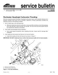
SERVICE MANUAL NUMBER 14Trim Cylinder Repair<strong>TRIM</strong> CYLINDERSRemoval1. Disconnect UP trim hose from front hole on trim cylinder.2. Disconnect DOWN trim hose from hydraulic connector on gimbal housing. Plug holeswith suitable plug or (22-38609).dcba70261a -UP Hoseb-Front Hole On Trim Cylinderc -DOWN Hosed-Hydraulic Connector90-818177--3 APRIL 2001 Page 5B-3
<strong>TRIM</strong> CYLINDERS SERVICE MANUAL NUMBER 143. Remove front and rear power trim cylinder mounting hardware.acea -Front Anchor Pinb-Bushing (Port And Starboard) (4)c -Flat Washer (Port And Starboard) (2)d-E-ring (Port And Starboard) (2)e -Plastic Caps (Port And Starboard) (2)bd70176bdace70027a70026a -Rear Anchor Pinb-Bushing (Port And Starboard) (4)c -Flat Washer (Port And Starboard) (2)d-E-ring (Port And Starboard) (2)e -Plastic Caps (Port And Starboard) (2)bPage 5B-4 90-818177--3 APRIL 2001
<strong>TRIM</strong> CYLINDERS SERVICE MANUAL NUMBER 142. Remove DOWN trim hose from cylinder.aba -DOWN Trim Hoseb-Clamping Platec -Screwsc706783. Remove floating piston from cylinder and remove O-ring.baa -Floating Pistonb-Trim Cylinderc -O-ringc22131Page 5B-6 90-818177--3 APRIL 2001
SERVICE MANUAL NUMBER 144. Remove trim cylinder end caps (Use special tool 91-821709).<strong>TRIM</strong> CYLINDERSacba -Special Tool 91-821709b-Trim Cylinderc -Trim Cylinder End Cap716775. Remove and disassemble shock piston assembly. Be careful not to lose check balls.Refer to Reassembly section for explanation if spacer is missing from cylinder.hdefgcab70682a -Boltb-Spacerc -Washerd-Springs (3)e -Spring Pins (3)f -Check Balls (3)g-Shock Piston Assemblyh-O-ring2213290-818177--3 APRIL 2001 Page 5B-7
<strong>TRIM</strong> CYLINDERS SERVICE MANUAL NUMBER 146. Remove and disassemble end cap.ab70375d e d cafg h22131a -End Capb-Piston Rodc -Large O-ringd-Small O-ring (2)e -Continuity Springf -Rod Scraperg-Plain Washerh-Retaining Ring7. Remove small O-ring from end of piston rod.ba70682a -Small O-ringb-Piston Rod8. Clean all parts in solvent. Be sure all parts are dry before reassembly.Page 5B-8 90-818177--3 APRIL 2001
SERVICE MANUAL NUMBER 14Reassembly<strong>TRIM</strong> CYLINDERSIMPORTANT: DO NOT attempt to substitute trim cylinders from different models ordamage to drive unit and/or transom could result.CAUTIONEnsure work area and all <strong>com</strong>ponents are clean before reassembling trim cylinders.Power Trim <strong>com</strong>ponents can be<strong>com</strong>e damaged if dirt gets into system.NOTE: Before reassembly, lubricate all internal parts with Quicksilver Power Trim andSteering Fluid or SAE 10W-30 or 10W-40 Motor Oil.1. Install small O-ring into end of piston rod.baa -O-ringb-Piston Rod706822. Install small O-rings and continuity spring into end cap.3. Install rod scraper, plain washer and retaining ring into end cap.4. Install large O-ring onto outside diameter of end cap.90-818177--3 APRIL 2001 Page 5B-9
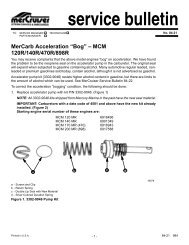
<strong>TRIM</strong> CYLINDERS SERVICE MANUAL NUMBER 145. Install end cap onto piston rod.ab70375d e d cafg ha -End Capb-Piston Rodc -Large O-ringd-Small O-ring (2)e -Continuity Springf -Rod Scraperg-Plain Washerh-Retaining Ring221316. Install large O-ring on shock piston.7. Install check ball, check ball eyelet, spring and spring pin into shock piston.IMPORTANT: The new trim cylinders provide the capability for an increased Trim-inrange. Spacer (u) can be removed from the trim cylinders to increase the Trim-inrange by approximately 1-1/2 degrees. This will improve the acceleration on someboats by forcing the bow down more quickly. If spacers are to be removed, the boatmust be tested to ensure the increased Trim-in range does not cause any undesiredboat handling characteristics (bow-steer, chine-walk, etc.) if the drive is trimmed-inwhile the boat is operated at higher speeds. The boat should be tested under allconceivable load conditions and maneuvers to ensure that the additional Trim-indoes not pose a problem. The final decision and responsibility for use of theadditional Trim-in range is left up to the boat manufacturer.WARNINGIt is re<strong>com</strong>mended that only qualified personnel perform the adjustment to the trimcylinders. Boat must be water tested after removing the spacers from the trim cylindersto ensure that the increased trim range does not cause the boat to exhibit anundesirable boat handling characteristic if the drive is trimmed in at higher speeds.The increased trim-in range may cause handling problems on some boats whichcould result in personal injury.Page 5B-10 90-818177--3 APRIL 2001
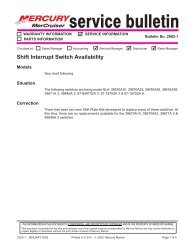
SERVICE MANUAL NUMBER 14<strong>TRIM</strong> CYLINDERS8. Install shock piston, three check balls, spring guide pins, springs, spring guide washer,spacer and bolt onto piston rod. Apply Loctite 27131 to threads of bolt. Torque to 17.5lb-ft (23.5 Nm).hdefgkabcij70682a -Boltb-Spacerc -Washerd-Springs (3)e -Spring Pins (3)f -Check Balls (3)g-Shock Piston Assemblyh-O-ringi -Check Ballj -Check Ball Eyeletk -Spring Pin2213290-818177--3 APRIL 2001 Page 5B-11
<strong>TRIM</strong> CYLINDERS SERVICE MANUAL NUMBER 149. Apply oil to parts. Install O-ring onto floating piston and insert floating piston into cylinder.70682aba -O-ringb-Pistonc -Cylinder22131IMPORTANT: Some boat configurations may require tilt-limit spacers to limit the totalupward travel of the drive unit. Be sure to install the same number of spacers thatwere originally removed. There must be an equal number in each cylinder.10. If required, install tilt-limit spacers.71678aa -Tilt Limit Spacers71679Page 5B-12 90-818177--3 APRIL 2001
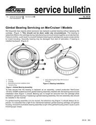
SERVICE MANUAL NUMBER 14<strong>TRIM</strong> CYLINDERSCAUTIONEnsure work area and all <strong>com</strong>ponents are clean before reassembling trim cylinders.Power Trim <strong>com</strong>ponents can be<strong>com</strong>e damaged if dirt gets into system.NOTE: Before reassembly, lubricate all internal parts with Quicksilver Power Trim andSteering Fluid or SAE 10W-30 or 10W-40 motor oil.CAUTIONDO NOT clamp center section of trim cylinder during reassembly. If clamping ofcylinder is necessary, clamp cylinder on front mounting flange.CAUTIONUse only 2-4-C Marine Lubricant with Teflon on end cap threads. Other substancesmay act as an insulator and cause poor electrical continuity between cap andcylinder which could cause a corrosion problem.11. Apply Special Lubricant 101 to end cap threads and install piston rod assembly intocylinder. Tighten end cap securely using a spanner wrench.12. Torque end cap at 45 lb-ft (61 Nm) using spanner wrench 91-821709.a70375bca -End Capb-Piston Rod Assemblyc -Cylinder7068290-818177--3 APRIL 2001 Page 5B-13
<strong>TRIM</strong> CYLINDERS SERVICE MANUAL NUMBER 1413. Position trim cylinder rear connecting ends as shown.abc70380a -Port Trim Cylinderb-Starboard Trim Cylinderc -Connecting Ends (Offset As Shown)14. Install DOWN trim hose.caba -DOWN Trim Hoseb-Clamping Platec -Screwsd-Check Painted Areas Of Trim Cylinders For Scratches That Expose Metal,Paint If Necessary.70676Page 5B-14 90-818177--3 APRIL 2001
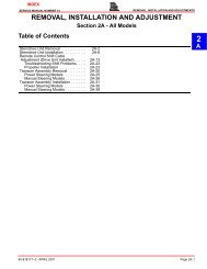
SERVICE MANUAL NUMBER 14Installation<strong>TRIM</strong> CYLINDERS1. Install trim cylinders forward mounting hardware as shown.2. Coat area in trim cylinder between bushings with 2-4-C Lubricant with Teflon.3. Replace anchor pin and install bushing(s) and washer(s).4. Attach E-ring(s) and plastic cap(s) to end of anchor pin.acebd70176a -Front Anchor Pinb-Bushing (Port And Starboard) (4)c -Flat Washer (Port And Starboard) (2)d-E-ring (Port And Starboard) (2)e -Plastic Caps (Port And Starboard) (2)5. Install trim cylinders rear mounting hardware as shown.6. Coat area in trim cylinder between bushings with 2-4-C Lubricant with Teflon.7. Replace anchor pin and install bushing(s) and washer(s).90-818177--3 APRIL 2001 Page 5B-15
<strong>TRIM</strong> CYLINDERS SERVICE MANUAL NUMBER 148. Attach E-ring(s) and plastic cap(s) to end of anchor pin.bdace70027aba -Rear Anchor Pinb-Bushing (Port And Starboard) (4)c -Flat Washer (Port And Starboard) (2)d-E-ring (Port And Starboard) (2)e -Plastic Caps (Port And Starboard) (2)700269. Reconnect trim hoses after air bleeding power trim cylinders and hoses followingprocedures outlined in Section 5A. (See Table of Contents.)Page 5B-16 90-818177--3 APRIL 2001
SERVICE MANUAL NUMBER 14THIS PAGE IS INTENTIONALLY BLANK<strong>TRIM</strong> CYLINDERS90-818177--3 APRIL 2001 Page 5B-17
<strong>TRIM</strong> CYLINDERS SERVICE MANUAL NUMBER 14THIS PAGE IS INTENTIONALLY BLANKPage 5B-18 90-818177--3 APRIL 2001