


You also want an ePaper? Increase the reach of your titles
YUMPU automatically turns print PDFs into web optimized ePapers that Google loves.
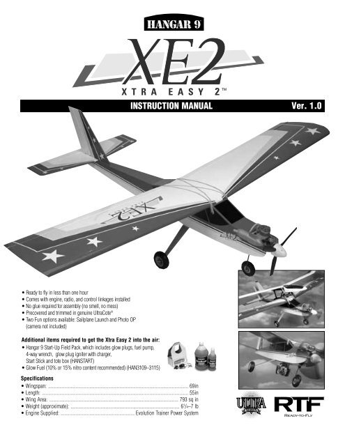
TMTMINSTRUCTION MANUALVer. 1.0• Ready to fly in less than one hour• Comes with engine, radio, and control linkages installed• No glue required for assembly (no smell, no mess)• Precovered and trimmed in genuine UltraCote ®• Two Fun options available: Sailplane Launch and Photo OP(camera not included)Additional items required to get the <strong>Xtra</strong> <strong>Easy</strong> 2 into the air:• <strong>Hangar</strong> 9 Start-Up Field Pack, which includes glow plugs, fuel pump,4-way wrench, glow plug igniter with charger,Start Stick and tote box (HANSTART)• Glow Fuel (10% or 15% nitro content recommended) (HAN3109–3115)Specifications• Wingspan: ................................................................................................................ 69in• Length: ..................................................................................................................... 55in• Wing Area: ....................................................................................................... 793 sq in• Weight (approximate): ....................................................................................... 6 1 /4–7 lb• Engine Supplied: ........................................................... Evolution Trainer Power System
Table of ContentsSmall Parts Layout . . . . . . . . . . . . . . . . . . . . . . . . . . . . . . . . . . . . . . . . . . . . . . . . . . . . . . . . . . . . . . . . . . . . . . . . . . . . . . . . . . . 2Large Parts Layout . . . . . . . . . . . . . . . . . . . . . . . . . . . . . . . . . . . . . . . . . . . . . . . . . . . . . . . . . . . . . . . . . . . . . . . . . . . . . . . . . . . 3Assembly Diagram . . . . . . . . . . . . . . . . . . . . . . . . . . . . . . . . . . . . . . . . . . . . . . . . . . . . . . . . . . . . . . . . . . . . . . . . . . . . . . . . . . . 4Section 1: Assemble the Wing . . . . . . . . . . . . . . . . . . . . . . . . . . . . . . . . . . . . . . . . . . . . . . . . . . . . . . . . . . . . . . . . . . . . . . . . . . 6Section 2: Install the Main Landing Gear and Wing Hold-Down Dowels . . . . . . . . . . . . . . . . . . . . . . . . . . . . . . . . . . . . . . . . . . . . 7Section 3: Install the Tail Surfaces . . . . . . . . . . . . . . . . . . . . . . . . . . . . . . . . . . . . . . . . . . . . . . . . . . . . . . . . . . . . . . . . . . . . . . . 8Section 4: Installing the Propeller on the Evolution Trainer Engine . . . . . . . . . . . . . . . . . . . . . . . . . . . . . . . . . . . . . . . . . . . . . . . . 9Final Assembly . . . . . . . . . . . . . . . . . . . . . . . . . . . . . . . . . . . . . . . . . . . . . . . . . . . . . . . . . . . . . . . . . . . . . . . . . . . . . . . . . . . . 11Control Checks . . . . . . . . . . . . . . . . . . . . . . . . . . . . . . . . . . . . . . . . . . . . . . . . . . . . . . . . . . . . . . . . . . . . . . . . . . . . . . . . . . . . 12Preflight Checks at the Field . . . . . . . . . . . . . . . . . . . . . . . . . . . . . . . . . . . . . . . . . . . . . . . . . . . . . . . . . . . . . . . . . . . . . . . . . . 13Evolution Trainer Power System . . . . . . . . . . . . . . . . . . . . . . . . . . . . . . . . . . . . . . . . . . . . . . . . . . . . . . . . . . . . . . . . . . . . . . . . 13Starting the Evolution Engine . . . . . . . . . . . . . . . . . . . . . . . . . . . . . . . . . . . . . . . . . . . . . . . . . . . . . . . . . . . . . . . . . . . . . . . . . . .15Flying your <strong>Xtra</strong> <strong>Easy</strong> Trainer . . . . . . . . . . . . . . . . . . . . . . . . . . . . . . . . . . . . . . . . . . . . . . . . . . . . . . . . . . . . . . . . . . . . . . . . . . 17Engine Adjustments . . . . . . . . . . . . . . . . . . . . . . . . . . . . . . . . . . . . . . . . . . . . . . . . . . . . . . . . . . . . . . . . . . . . . . . . . . . . . . . . . .17AMA Safety Code . . . . . . . . . . . . . . . . . . . . . . . . . . . . . . . . . . . . . . . . . . . . . . . . . . . . . . . . . . . . . . . . . . . . . . . . . . . . . . . . . . . 18Glossary of Terms . . . . . . . . . . . . . . . . . . . . . . . . . . . . . . . . . . . . . . . . . . . . . . . . . . . . . . . . . . . . . . . . . . . . . . . . . . . . . . . . . . 20Small PartsA. #64 Rubber BandsB. Wing DowelsC. Transmitter/Receiver ChargerD. Radio Frequency IdentifiersE. Servo AccessoriesF. Tail and Landing Gear HardwareG. Center Wing TapeMiscellaneous PackageA. #64 Rubber BandsB. Wing DowelsC. Transmitter/Receiver ChargerD. Radio FrequencyIdentifiersE. Servo AccessoriesG. CenterWing TapeF. Tail and Landing Gear Hardware2
Large Parts1. Tail Assembly2. Fuselage3. Main Landing Gear4. Engine (Evolution Trainer Power System)5. Transmitter (JR 421EX)6. Wings7. Nose Gear1. Tail Assembly2. Fuselage3. Main Landing Gear4. Engine(Evolution TrainerPower System)5. Transmitter (JR 421EX)6. Wings 7. Nose Gear3
Assembly Diagram (For reference only)Please carefully read through the entire instruction manualbefore beginning assembly of your <strong>Xtra</strong> <strong>Easy</strong> 2Ready-To-Fly (RTF) kit.Tape Strip1. Assemble the wing2. Mount the main landing gearShort Screws4
3. Install thetail surfacesLarge WashersSmall WashersLong ScrewsRubber Bands (5 per side) to hold wing5
Section 1: Assemble the WingBottom view of wingStep 1-1Remove shipping tape.Step 1-4Attach clevis.Step 1-3Wrap suppliedclear tape aroundthe center joint.Step 1-2Slide both wing panels ontothe metal tube.Carefully remove the contents of the <strong>Xtra</strong> <strong>Easy</strong> 2 RTF kit. It isrecommended that you charge the transmitter and receiver batteriesfor 24 hours prior to flying your model.Step 1. Remove each wing from its protective plastic bag.Remove the pieces of tape that hold the ailerons in place forshipping. The hinges in the <strong>Xtra</strong> <strong>Easy</strong> 2 Trainer have alreadybeen glued in place during manufacturing. Check the aileronsfor freedom of movement by flexing them up and down severaltimes.Step 2. Locate the aluminum wing tube and carefully slide itinto the opening in one of the wing halves. The fit may be snug,so use a twisting motion while inserting the tube. There is ashort metal pin located near the trailing edge that will key intothe opposite wing panel and keep the wing from rotating aroundthe wing tube. Carefully slide the other wing half onto the wingtube. Align the metal pin with its hole and press the wingpanels together.Step 3. Locate the wing joiner tape and apply it to the top andbottom of the wing along the joint. Start at the top of the trailingedge and wrap it around the front of the wing and to the bottomtrailing edge.Step 4. The aileron servo lead has been tied around the linkagefor shipment. Untie the servo lead to free up the aileronlinkage. Note that the lead has been labeled with a piece oftape; do not remove this tape. One of the aileron linkages hasalready been connected to the aileron and secured with a smallpiece of tubing (clevis keeper). This is done to prevent theclevis from opening during flight.Connect the other aileron linkage to the aileron and snap theclevis in place. Slide the clevis keeper over the clevis to securethe linkage to the aileron.6
Section 2. Installing the Main Landing Gear andWing Hold-Down DowelsShort ScrewApply threadlock to threads of the screws priormounting to landing gear.Step 2-1Mount landing gear to fuselagewith the two screws provided.Step 2-2Step 1. Locate the aluminum main landing gear. The wheelshave already been attached. You should have two screwsremaining from the hardware package. Apply a drop of threadlockto each screw. Then, insert them through the holes in thelanding gear and attach the landing gear to the fuselage.Step 2. Locate the two wing hold-down dowels and insertone into each of the two holes located in the fuselage, usinga careful twisting motion to install. The dowels should bepositioned so an equal amount is projecting from either sideof the fuselage.7
Anmeldung zur BA-Arbeit• § 14 Abs. 1 Satz 2: „Wird das Thema derBachelorarbeit aus dem vorangegangenenSeminar zugeteilt, entfällt ein gesondertesAnmeldeverfahren.“• Dieses gesonderte Anmeldeverfahren wird vomLehrstuhl nicht angeboten!• Bitte melden Sie sich (wie bisher) zu allenAbschlussarbeiten zentral über das Prüfungsamtan; Anmeldungen über den Lehrstuhl sind nurbei Praxisarbeiten möglich!03.02.2010 Seminarvorbesprechung 10
Control ChecksThe correct servo directions are pre-adjusted, but it’s a goodidea to confirm the correct direction. After charging the transmitterand receiver batteries per the instruction included withthe radio, turn on the transmitter and airplane and check thatthe controls are moving in the correct direction, as per theillustrations below.Elevator: Moving theright stick down shouldcause the elevator tomove upward. Pushingthe right stick up willcause the elevator tomove down.Ailerons: Moving theright stick to the rightshould move the rightaileron up and the leftaileron down. Moving thestick in the oppositedirection will give theopposite result.AILERONELEVATORAILERONIt is very important that you make sure the control surfaces(elevator, ailerons and rudder) are at 0 degrees when the transmittercontrol sticks and trim levers are centered. Turn on yourtransmitter and receiver. Make sure the rudder, elevator andaileron sticks are centered and the trim levers are centered. Usea ruler to place against the control surfaces to see if there areany deflections from the center (0 degrees).Threading the clevis in or out on the control rod makes adjustmentsto the control surfaces. Threading in causes the surfaceto move toward the rod. Threading out causes the surface tomove away from the rod. Set the control surfaces, elevator,ailerons and rudder to 0 degrees.Reconnect the clevises to the outer hole of the control horn ofthe rudder and elevator control horns. Make sure that the cleviskeepers are in place.0°Rudder: Moving the leftstick to the right shouldmove the rudder to theright. Moving the stick tothe left moves the rudderto the left.RUDDERThrottle: Look into thecarburetor. With the throttle(left stick) in the upperposition, the carburetorshould be fully open.With the throttle stick inthe lower position andthe trim lever centeredthe carburetor should be1/16” open.CARBURETORFull open1/16”12
Evolution Trainer Power System (continued)Before using, remove any flashing along the edges of thepropeller by scraping it with a sharp knife.Only use a “chicken stick” or electric starter to start the engine.Keep spectators at least 20 feet away and out of the path of arotating propeller.20 feetOnly make adjustments to the carburetor from behind theengine.Wear safety glasses and hand protection when operating modelengines. Do not permit any objects to touch a turning propeller.Remain clear of the propeller plane of rotation.14
Evolution Trainer Power System (continued)To stop the engine, cut off the fuel and air supply by movingthe throttle stick and trim lever down to close the carburetor.Do not stop the propeller with your hand or other object.Inspect the propeller after each flight; discard any propeller thathas nicks scratches, or any other visible defect. Do not repair,alter or in any way modify a propeller. Replacement propellersare available through your local hobby retailer (EVOE100P).Starting the Evolution EngineField Equipment NeededThe following are included in the <strong>Hangar</strong> 9 ® Start-Up Fieldpack (HANSTART)Sturdy cardboard construction Tote BoxManual fuel pumpTwo <strong>Hangar</strong> 9 glow plugs4-way wrenchRechargeable glow driver with chargerChicken stickOther Items Needed (not included in Start-UpField Accessory pack)Fuel, 10 to 15% nitro content (Cool Power or Powermasterrecommended)Electric Starter (optional)Step 1. Fill the fuel tank with the proper fuel. We recommend10% or 15% Nitro content such as Cool Power or Powermasterfuel. Fill the tank by connecting the fuel pump to the line that isconnected to the remote needle valve assembly. Disconnect thefuel line attached to the pressure fitting of the muffler; your tankis full when fuel begins to run out of the pressure line. Reconnectthe fuel lines to the needle valve assembly and muffler.Note: It is very important to reconnect the fuel lines tothe correct fitting. If they are reconnected incorrectly theengine will not run properly.15
Starting the Evolution Engine (continued)Step 2. To prime your engine, first turn on your transmitterand then your receiver. Move the throttle to full open and placeyour finger over the carburetor opening. Turn the propeller overby hand six full turns thus priming the engine. Move the throttlestick full down to idle.Step 3 photoStep 4. Allow the engine to idle for 30 seconds. Adjust thetrim lever if necessary to achieve a constant idle.Caution: Always have a helper hold your plane whenstarting.Step 3. Move the throttle trim lever to the middle position.Place the glow driver on the glow plug and using a start stickturn the propeller counter clockwise through the compressionstroke. You should feel a bump against the start stick. Whenyou feel the bump, flip the propeller counter clockwise to startthe engine. Repeat the process if the engine does not start.Note: The flywheel will allow the Evolution engine toidle reliably at incredibly low speeds. With the glowdriver still attached advance the throttle to full throttleand then back to idle. Remove the glow driver.16
AMA SAFETY CODE2003 Official AMA National Model Aircraft Safety CodeEffective January 1, 2003Model Flying MUST be in accordance with this Code in orderfor AMA Liability Protection to apply.GENERAL1) I will not fly my model aircraft in sanctioned events, airshows, or model flying demonstrations until it has been provento be airworthy by having been previously, successfully flighttested.2) I will not fly my model higher than approximately 400 feetwithin 3 miles of an airport without notifying the airport operator.I will give right-of-way and avoid flying in the proximityof full-scale aircraft. Where necessary, an observer shall beutilized to supervise flying to avoid having models fly in theproximity of full-scale aircraft.3) Where established, I will abide by the safety rules for the flyingsite I use, and I will not willfully and deliberately fly mymodels in a careless, reckless and/or dangerous manner.4) The maximum takeoff weight of a model is 55 pounds,except models flown under Experimental Aircraft rules,5) I will not fly my model unless it is identified with my nameand address or AMA number, on or in the model. (This doesnot apply to models while being flown indoors.)6) I will not operate models with metal-bladed propellers orwith gaseous boosts, in which gases other than air enter theirinternal combustion engine(s); nor will I operate models withextremely hazardous fuels such as those containing tetranitromethaneor hydrazine.7) I will not operate models with pyrotechnics (any device thatexplodes, burns, or propels a projectile of any kind) including,but not limited to, rockets, explosive bombs dropped frommodels, smoke bombs, all explosive gases (such as hydrogenfilled balloons), ground mounted devices launching a projectile.The only exceptions permitted are rockets flown in accordancewith the National Model Rocketry Safety Code or those permanentlyattached (as per JATO use); also those items authorizedfor Air Show Team use as defined by AST Advisory Committee(document available from AMA HQ). In any case, models usingrocket motors as a primary means of propulsion are limited to amaximum weight of 3.3 pounds and a G series motor. Note:( Amodel aircraft is defined as an aircraft with or without engine,not able to carry a human being.)8) I will not consume alcoholic beverages prior to, nor during,participation in any model operations.9) Children under 6 years old are only allowed on the flight lineas a pilot or while under flight instruction.RADIO CONTROL1) I will have completed a successful radio equipment groundrange check before the first flight of a new or repaired model.2) I will not fly my model aircraft in the presence of spectatorsuntil I become a qualified flier, unless assisted by an experiencedhelper.3) At all flying sites a straight or curved line(s) must be establishedin front of which all flying takes place with the other sidefor spectators. Only personnel involved with flying the aircraftare allowed at or in the front of the flight line. Intentional flyingbehind the flight line is prohibited.4) I will operate my model using only radio control frequenciescurrently allowed by the Federal Communications Commission.(Only properly licensed Amateurs are authorized to operateequipment on Amateur Band frequencies.)5) Flying sites separated by three miles or more are consideredsafe from site-to site interference, even when both sites use thesame frequencies. Any circumstances under three miles separationrequire a frequency management arrangement which maybe either an allocation of specific frequencies for each site ortesting to determine that freedom from interference exists.Allocation plans or interference test reports shall be signed bythe parties involved and provided to AMA Headquarters.Documents of agreement and reports may exist between (1) twoor more AMA Chartered Clubs, (2) AMA clubs and individualAMA members not associated with AMA Clubs, or (3) two ormore individual AMA members,6) For Combat, distance between combat engagement line andspectator line will be 500 feet per cubic inch of engine displacement.(Example: .40 engine = 200 feet.); electric motorswill be based on equivalent combustion engine size. Additionalsafety requirements will be per the RC Combat section of thecurrent Competition Regulations.7) At air shows or model flying demonstrations a singlestraight line must be established, one side of which is forflying, with the other side for spectators.8) With the exception of events flown under AMA Competitionrules, after launch, except for pilots or helpers being used, nopowered model may be flown closer than 25 feet to any person.9) Under no circumstances may a pilot or other person touch apowered model in flight.18
AMA SAFETY CODE (continued)Organized RC Racing Event10) An RC racing event, whether or not an AMA Rule Bookevent, is one in which model aircraft compete in flight over aprescribed course with the objective of finishing the coursefaster to determine the winner.A. In every organized racing event in which contestants,callers and officials are on the course:1. All officials, callers and contestants mustproperly wear helmets, which are OSHA, DOT,ANSI, SNELL or NOCSAE approved or comparablestandard while on the racecourse.2. All officials will be off the course except forthe starter and their assistant.3."On the course" is defined to mean any areabeyond the pilot/staging area where actual flyingtakes place.B. I will not fly my model aircraft in any organized racingevent which does not comply with paragraph Aabove or which allows models over 20 pounds unlessthat competition event is AMA sanctioned.C. Distance from the pylon to the nearest spectator(line) will be in accordance with the currentCompetition Regulations under the RC Pylon Racingsection for the specific event pending two or threepylon course layout.11) RC Night flying is limited to low performance models (lessthan 100 mph). The models must be equipped with a lightingsystem that clearly defines the aircraft's attitude at all times.19
Glossary of TermsAilerons: Each side of this airplane has a hinged control surface,called an aileron, located on the trailing edge of the wing.Move the aileron stick on the transmitter left, the left aileronmoves up and the right aileron moves down. Moving the leftaileron up causes more drag and less lift causing the wing todrop down. When the right aileron moves down, more lift iscreated, causing the wing to rise. This interaction causes theairplane turn or roll to the left. Perform the opposite actions,and the airplane will roll to the right. This is how you controlthe airplane’s direction in flight.Carburetor: By adjusting the needle valve in the carburetor,you control the engine’s lean/rich fuel mixture and determinethe airplane’s speed.Charger: This is the device used to charge/recharge batteries.If Ni-Cd batteries are provided with the radio, a charger is usuallyprovided as well.Clevis: The Clevis connects the wire end of the pushrod to thecontrol horn of the control surface. A small clip, the clevis hasfine threads so that you can adjust the length of the pushrod.Clunk: Located in the fuel tank, a clunk is weighted andensures that the intake line has a steady supply of fuel.Computer Radio: By using advanced programming functionsof the transmitter, you can adjust the airplane without changingany mechanical structures.Control Horn: This arm connects the control surface to theclevis and pushrod.Control Surfaces: The moveable part of the wing and tailthat causes the aircraft to roll (aileron), pitch (elevator) or yaw(rudder).Dead Stick: When the airplane is in flight gliding, without theengine running, it is called “dead stick”.Dihedral: The degree of angle (V-shaped bend) at which thewings intersect the plane is called dihedral. More dihedral givesan airplane more aerodynamic stability. Some sailplanes andtrainer planes with large dihedral dispense with ailerons anduse only the rudder to control the roll and yaw.Electric Starter: This is the small motor commonly used tostart the airplane’s engine.Elevator: The hinged control surface functions as an elevator,which you adjust to control the airplane’s pitch axis. Pulling thetransmitter’s control stick toward the bottom of the transmitteradjusts the elevator upward, and the airplane begins to climb.Push the control stick forward, and the airplane begins to dive.Expanded Scale Voltmeter (ESV): This device is used tocheck the voltage of the battery pack.Flight Box: The box in which you store and transport your flyingequipment is called a flight box.Flight Pack or Airborne Pack: These interchangeable termsdescribe the radio equipment that is installed on the airplane.Fuel Overflow Line (Vent): This line pressures the fuel tankand provides an even fuel flow to the engine. It also functionsas an overflow line when the fuel tank is full.Fuel Pickup Line: This line connects the fuel tank to the carburetor,usually with a clunk on the tank end to keep the fuelflowing while the aircraft is in flight.Fuselage: The main body of an airplane.Glow Plug Clip/Battery: A 1.2-volt battery with a clip, whichis connected to your engine’s glow plug and is used to start theengine. You remove it once the engine is running smoothly.High Wing: The term describes an airplane that has its wingsmounted on the top of the fuselage.Hinge: Moving blades on the control surface that allow you tocontrol the airplane’s movement. All hinges must be gluedproperly and securely to prevent the airplane from crashing.(This has already been done for you on the <strong>Easy</strong> Fly)Horizontal Stabilizer: The horizontal surface of the tail givesthe airplane stability while in flight.Leading Edge: The front of a flying surface.Main Landing Gear: The wheel and gear assembly the airplaneuses to land. It is attached to the bottom of the fuselage.Muffler: This device muffles engine noise and increases thebackpressure from the engine’s exhaust stack, which canimprove the airplane’s performance at low speeds.Needle Valve: This mechanism within the carburetor adjuststhe fuel mixture and throttle. Refer to your instructions fordirections on how to adjust the needle valve.Ni-Cd: This abbreviation stands for Nickel Cadmium, thechemical compound used in rechargeable batteries.Nitro: Short for nitromethane, a fuel additive that improves anairplane’s high-speed performance. 10% to 15% nitro contentis recommended forNose Gear: The part of the landing gear that is attached to thenose of the fuselage. The nose gear is usually connected to therudder servo to help you steer the airplane on the ground.Pitch Axis: The horizontal plane on which the airplane’s noseis raised or lowered. By adjusting the elevator, you can raise theairplane’s nose above the pitch axis (climb) or lower it belowthe pitch axis (dive).20
Glossary of Terms (continued)Pushrod: The rigid mechanism that transfers movement fromthe servo to the control surface.Receiver: The receiver unit in the airplane receives your signalsfrom the ground transmitter and passes the instructionsalong to the airplane’s servos.Roll Axis: The horizontal plane on which the airplane’s wingsare raised or lowered. By adjusting the ailerons, you can drop awing tip below the roll axis and cause the airplane to bank orroll.Rudder: The hinged control surface on the vertical stabilizerthat controls the airplane’s yaw. Moving the rudder to the leftcauses the airplane to yaw left; moving the rudder to the rightcauses it to yaw right.Servo: The servo transforms your ground commands intophysical adjustments of the airplane while it’s in the air.Servo Output Arm: A removable arm or wheel that connectsthe servo to the pushrod - also called servo horn.Spinner: Term describing the nose cone that covers thepropeller hub.Switch Harness: This switch is commonly located on thefuselage and governs the On/Off mechanism for the flight pack.Tachometer: A device that measures the engine’s rpm (rotationsper minute) by counting light impulses that passesthrough the spinning propeller.Threadlock: A liquid that solidifies; used to prevent screwsfrom loosening due to vibration.Torque Rods: Inserted into the ailerons, these rigid wire rodsrun along the wing’s trailing edge, then bend downward andconnect to the pushrod.Trainer Airplane: Designed to fly with high stability at lowspeeds, a trainer model airplane allows new users some extrareaction time as they learn to control the airplane’s movements.Transmitter: The device used on the ground to transmitinstructions to the airplane. Three transmitter modes are usedin model airplanes. The most common is Mode 2, where the leftstick controls the throttle and rudder, and the right stick controlsthe elevator and ailerons.Vertical Stabilizer: The vertical surface of the tail gives theairplane stability while in flight.Wheel Collar: The round retaining piece that anchors wheelsin place on the wheel axle.Wing: Because wings provide the primary lifting force on anairplane, adjustments to the wings affect the airplane’s movementswhile in flight.Yaw Axis: The vertical plane through which the airplane’s nosepasses as it yaws to the left or to the right. The rudder controlsthe yaw axis.Z-Bend: The wire ends of pushrods have Z-shaped bendswhich attach to the servo.21
© Copyright 2003, Horizon Hobby, Inc.www.horizonhobby.com5340


