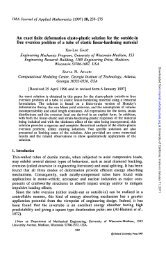
4Practical numerical evaluation of the T -integralFigure 2 is a blowup of a ®nite element mesh where a crackis propagating. <strong>The</strong> crack growth direction is a symmetryplane, hence only half the mesh is present for this twodimensional problem. In Fig. 2a, a rectangular path, C e ,isde®ned, which is of size 3h parallel to, and perpendicularto, the current crack location. Note that in practice thepath de®nitions are usually square rather than circular.After loading and permitting elastic-plastic and/or creepstraining, but before crack growth, we may calculate theT -integral as the line integral:ZT ˆ ‰Wn 1 t i u i;1 ŠdC: …8†C eˆ3hAfter the crack grows (Fig. 2b), one may also evaluate T along the stretched ``Dugdale'' path, ~C eˆ3h , where e ˆ 3hfor a growing crack is understood as the distance in frontof and perpendicular to the current crack tip, also usingEq. 8. Note that if we evaluate the integral along the dashpath (C e , Fig. 2b, which is analogous to the moving path ofFigs. 1a and 2a), we obtain signi®cant errors in the calculatedvalues of all the integrals. <strong>The</strong> source of thesenumerical errors is discussed in the next paragraph.<strong>The</strong>re is an important practical reason for requiring T to be evaluated on a Dugdale-type path such as in Figs. 1bor 2b. Consider crack growth to be modeled by a noderelease technique in a ®nite element model (Fig. 2). If weconsider a dashed path in Fig. 2b (i.e., the square path thatmoves with the crack tip with the center at the currentcrack tip) through the ®nite element mesh at the currentcrack tip, a 0 ‡ Da ˆ a, then two elements model thecomplete angular variation of the crack tip ®elds from 0 top at the crack tip, with the coordinate system as in Fig. 1aor 1b. It is clear that this mesh discretization is grosslyinadequate and that the calculated stresses, strains, etc., inthe growing wake region are incorrect. If one attempts toevaluate T along a square path which passes throughthese crack wake elements, large errors are introduced intoFig. 2a,b. Integral de®nitions of paths: a Initial Crack b Aftercrack growthT (i.e., in effect, T cannot be calculated accurately).Moreover, if one uses a moving crack tip mesh to modelcrack growth, the errors associated with mesh shifting andremeshing lead to similar errors if C e is circular or square(see Brust, Nishioka, Nakagaki and Atluri (1985)). Kostylevand Margolin (1993) in their studies of the use of T tocharacterize elastic-plastic crack growth found no need forthe use of a `Dugdale' type path. <strong>The</strong>y found that using themoving square path of Fig. 2 gave good results. Our experiencedoes not indicate that this is possible unless theinelastic zone at the growing crack tip is very small. Itshould be noted that the above comments are equallyapplicable with the EPFEAM method.In actual numerical calculations, it is more convenientto evaluate the integrals as follows. We may write (usingthe divergence theorem and equilibrium considerations):T j e ˆ 0 ˆ lim ‰Wn 1 t i u i;1 ŠdC …9†C eˆ0ZZT j eˆ0 ˆ ‰Wn 1 t i u i;1 ŠdC ‡ ‰W ;1 …r ij e ij;1 †ŠdVC f V fe!0Z…10†where C f is a path which encircles the crack far from thecrack tip, and V f is the volume within C f . <strong>The</strong> numericalvalue for Eq. 9 may be zero for elastic-perfectly-plastic rateindependent materials, but is non-zero for elastic, hardeningplastic, and high strain rate viscoplastic materials.Note that T j eˆ0 of Eq. 10 is path independent for any C f .This path independence is irrelevant, except as a check onmesh size re®nement. We have found that lack of pathindependence when T j eˆ0 is evaluated along many paths,C f and using Eq. 10 are a clear indication to improve themesh re®nement and reanalyze the problem.<strong>The</strong>n, to evaluate the integral for a given e :ZT j eˆ3h ˆ ‰W n1 t i u i;1 ŠdCC fZ…11†‰W ;1 …r ij e ij;1 †ŠdV:V f V eˆ3hThus, it is convenient to evaluate all of the integrals usingEq. 11 (or a similar form for other integrals) and thensubtract out the V e term for each path size, e, of interest.Since it is simple to store the V e value in each element, oneonly needs to know the current crack tip location, and thee values to evaluate the integrals. In practice, we havefound that a buffer zone of at least two elements (for 8-node isoparametric elements) is often required. Thismeans that, in Fig. 2, e 2h. Smaller values can result ininaccuracies. However, some recent applications using theelastic plastic ®nite element alternating method have enabledonly one large element to be used along the crackgrowth direction. Also, e should be large enough to bebeyond the process or large strain zone.We generally evaluate the integrals for ®ve or six valuesof e, the minimum e being de®ned as the length of twoelements. Since the numerical value of the integrals dependson e, we thus have ®ve or six different resistancecurves which can be used as the fracture resistance curvefor another history dependent analysis prediction. In373
374principle, each resistance curve should be able to characterizefracture as long as e is not too large. For large e, theenergy lost through ~C e becomes divorced from the cracktip dissipation energy and, thus, will not characterizehistory-dependent fracture. For a stationary crack, theenergetic interpretation of these integrals is not appropriate.<strong>The</strong> philosophy of characterizing an elastic-plastic orcreep crack growth process via the T -integral parametermay be described as follows. A material resistance curve isdeveloped by performing an experiment on a laboratoryfracture specimen. This analysis phase has been termed`generation phase' analysis by Kanninen (1978) and Kanninenand Popelar (1986) since the purpose is to generatethe resistance curve. <strong>The</strong> experiment is then modeled viathe ®nite element method where the T -integral is calculatedalong several small ®nite-sized paths. This numericalexperiment then produces the material resistance curve(s),which depend on the path size de®nitions, e. In principle,any of these path size de®nitions may be used as long as eis not too small so that numerical errors occur or too largeso that the energy dissipated is divorced from crack tipevents. <strong>The</strong> behavior of other arbitrarily loaded andcracked structures can then be predicted by modeling thetime history of loading and using this generated resistancecurve (as de®ned by e) as a crack growth criterion. <strong>The</strong>resistance curve is assumed to be an intrinsic materialproperty. <strong>The</strong> time history of crack initiation and growthmay thus be predicted. <strong>The</strong> analogy to elastic-plasticfracture mechanics based upon the J-integral may bemade.Also, for engineering predictions, the methods may beused as an empirical parameter-rate type of approach byrelating _a or da/dN to the rates or changes in the parameter.This has been done, as will be summarized in thenext section.5Example Applications of the T -integralThis section reviews some of the work performed to datewhich uses T -integral methodology to predict crackgrowth and fracture of cracked specimens and servicestructures. In the following, we are only concerned withstudies which illustrate the use of the method and providevalidation. <strong>The</strong> validation of this method can only beachieved by comparing predictions with experimental results.We ®rst review the literature to summarize the workthat has been performed which validates the T -integralmethodology. Next, several detailed examples, taken fromthis literature, are provided which illustrate the performanceof the method. It should be noted that the Part IIIreport in this series provides a number of new predictionsof residual strength for the multi-site-damage problem.<strong>The</strong> examples shown in the following section considerhistory dependent elastic-plastic fracture, creep fracture,and some earlier predictions of MSD using EPFEAM.<strong>The</strong> ®rst practical validation of the T technique wasshown by Brust, Nishioka, Nakagaki, and Atluri (1985) andBrust, McGowan, and Atluri (1986a). This work consideredelastic-plastic stable crack growth as well as the effect ofunloading on the stable crack growth process and clearlyshowed that T could capture the history dependent crackgrowth processes while the classical parameters (the J-integraland the crack tip opening angle) could not. An exampleof this work will be shown later. Brust and Atluri(1986b) also considered and validated that creep crackgrowth could be modeled using T , although veri®cationwas not provided.It is interesting to point out that, after this originalvalidation work, there was about a ®ve-year lag beforemore studies were made. <strong>The</strong> main reasons for this delayin further veri®cation work were twofold: <strong>The</strong> T -integral methodology received criticism in severalearly papers after the original publications showingits practical utility. As was shown earlier and will beillustrated in some of the examples to be presented later,this criticism was unfounded. However, as is usuallythe case, it takes some time for a new technique in any®eld to receive widespread acceptance. <strong>The</strong> issue of how practical the method is for analyzingservice structures was an important issue early on sincecomputational methods were required. <strong>The</strong> method wasconsidered nice theory, but was not practical sincecomplex and detailed ®nite element analyses were requiredto apply it. However, as will be seen in one of theexamples to be discussed later, the development of theNonlinear <strong>Finite</strong> <strong>Element</strong> <strong>Alternating</strong> <strong>Method</strong>(NLFEAM), which is an advanced and computationallyextremely ef®cient fracture analysis methodology whichhas emerged recently, renders the T methodologypractical for modeling service structures.Since 1992, however, a number of publications whichverify the predictive ability of the T -integral methodologieshave appeared. Kim et al. (1992) showed that DT could characterize the complex creep-fatigue crack growthprocess under the severe service conditions experienced inthe space shuttle main engine environment. Other classicalfracture parameters produced poor results compared withthe extensive experimental data that was compiled in thisprogram. Also Liu, Han, and Yan (1992) showed that T can characterize large scale creep crack growth whileclassical creep parameters again failed to perform. In 1993,Kostylev and Margolin (1993), in the context of elasticplasticcrack growth, illustrated the ability of T to characterizequasi-static and dynamic crack response. From1992 to the present, Brust and co-workers (1994±1995)have shown that the T -integral can characterize the hightemperature history dependent crack growth response ofseveral steel alloys used in fossil fueled energy productionfacilities. An example of this work is presented later. Experimentalmethods to evaluate the T -integral have alsobeen recently developed (see Okada, Suzuki, Ma, Lam,Pyo, and Atluri (1995)). Finally, since 1994 Atluri and coworkers(1994-1995) have veri®ed that T can characterizethe multi-site damage induced by multiple cracks in anaircraft fuselage. This work introduced the <strong>Elastic</strong> <strong>Plastic</strong><strong>Finite</strong> <strong>Element</strong> <strong>Alternating</strong> <strong>Method</strong>ology (EPFEAM) whichis a great advancement to nonlinear computational fracturemechanics analysis procedures since it permits simple,fast, and cheap analyses to be performed using the T theory. An example from this work is illustrated also.