

The Draper Technology Digest - Draper Laboratory
The Draper Technology Digest - Draper Laboratory
The Draper Technology Digest - Draper Laboratory

You also want an ePaper? Increase the reach of your titles
YUMPU automatically turns print PDFs into web optimized ePapers that Google loves.
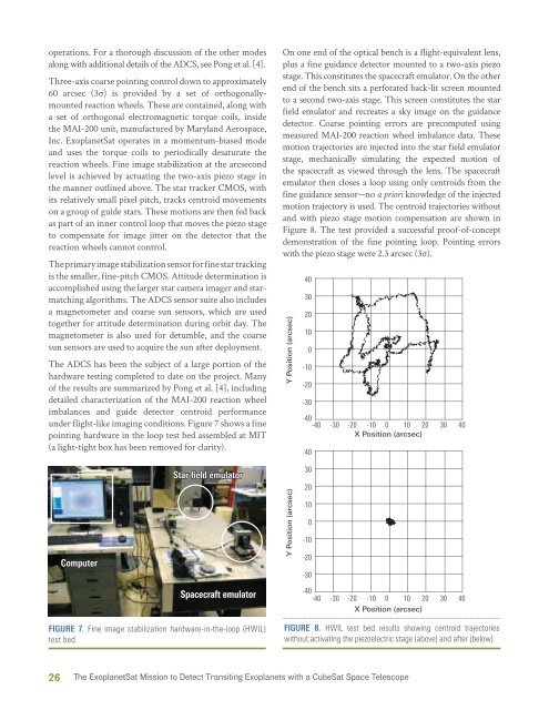
operations. For a thorough discussion of the other modesalong with additional details of the ADCS, see Pong et al. [4].Three-axis coarse pointing control down to approximately60 arcsec (3σ) is provided by a set of orthogonallymountedreaction wheels. <strong>The</strong>se are contained, along witha set of orthogonal electromagnetic torque coils, insidethe MAI-200 unit, manufactured by Maryland Aerospace,Inc. ExoplanetSat operates in a momentum-biased modeand uses the torque coils to periodically desaturate thereaction wheels. Fine image stabilization at the arcsecondlevel is achieved by actuating the two-axis piezo stage inthe manner outlined above. <strong>The</strong> star tracker CMOS, withits relatively small pixel pitch, tracks centroid movementson a group of guide stars. <strong>The</strong>se motions are then fed backas part of an inner control loop that moves the piezo stageto compensate for image jitter on the detector that thereaction wheels cannot control.<strong>The</strong> primary image stabilization sensor for fine star trackingis the smaller, fine-pitch CMOS. Attitude determination isaccomplished using the larger star camera imager and starmatchingalgorithms. <strong>The</strong> ADCS sensor suite also includesa magnetometer and coarse sun sensors, which are usedtogether for attitude determination during orbit day. <strong>The</strong>magnetometer is also used for detumble, and the coarsesun sensors are used to acquire the sun after deployment.<strong>The</strong> ADCS has been the subject of a large portion of thehardware testing completed to date on the project. Manyof the results are summarized by Pong et al. [4], includingdetailed characterization of the MAI-200 reaction wheelimbalances and guide detector centroid performanceunder flight-like imaging conditions. Figure 7 shows a finepointing hardware in the loop test bed assembled at MIT(a light-tight box has been removed for clarity).On one end of the optical bench is a flight-equivalent lens,plus a fine guidance detector mounted to a two-axis piezostage. This constitutes the spacecraft emulator. On the otherend of the bench sits a perforated back-lit screen mountedto a second two-axis stage. This screen constitutes the starfield emulator and recreates a sky image on the guidancedetector. Coarse pointing errors are precomputed usingmeasured MAI-200 reaction wheel imbalance data. <strong>The</strong>semotion trajectories are injected into the star field emulatorstage, mechanically simulating the expected motion ofthe spacecraft as viewed through the lens. <strong>The</strong> spacecraftemulator then closes a loop using only centroids from thefine guidance sensor—no a priori knowledge of the injectedmotion trajectory is used. <strong>The</strong> centroid trajectories withoutand with piezo stage motion compensation are shown inFigure 8. <strong>The</strong> test provided a successful proof-of-conceptdemonstration of the fine pointing loop. Pointing errorswith the piezo stage were 2.3 arcsec (3σ).Y Position (arcsec)403020100-10-20-30-40-40 -30 -20 -10 0 10 20 30 40X Position (arcsec)40ComputerStar field emulatorY Position (arcsec)3020100-10-20-30Spacecraft emulator-40-40 -30 -20 -10 0 10 20 30 40X Position (arcsec)FIGURE 7. Fine image stabilization hardware-in-the-loop (HWIL)test bed.FIGURE 8. HWIL test bed results showing centroid trajectorieswithout activating the piezoelectric stage (above) and after (below).26 <strong>The</strong> ExoplanetSat Mission to Detect Transiting Exoplanets with a CubeSat Space Telescope


