Safe Mode Spacecraft SensorIdentifying and implementing simple, reliable,independent, and affordable (in terms of cost, mass,and power) methods for autonomous satellite safingand protection has long been a significant challenge forspacecraft designers. One notional safe-hold operationalconcept calls for an MGU unit to be powered off atlaunch. <strong>The</strong> MGU could be powered on autonomouslyupon indication of spacecraft separation from its launchvehicle. In this state, the outputs of the MGU wouldprovide sufficient angular rate polarity feedback tostabilize the observatory if in a tumbling state due to hightip-off rates at separation. <strong>The</strong> MGU could also providea coarse attitude acquisition function prior to handingover attitude determination to the observatory’s precisionattitude sensors, or in some cases, the payload’s fineguidance sensor. <strong>The</strong> MGU could be left in a low-poweredstate during normal mission operations and would only befully activated when a safe-hold event is triggered by theobservatory’s fault detection logic. <strong>The</strong> low-power drawof the MGU would be compatible with the initial phase ofsafe-hold operations when only very limited battery powermay be available. Additionally, the safe-hold MGU couldserve as a backup to unforeseen attitude determination andcontrol system (ADCS) assembly and logic errors wherethe primary IMU is compromised and ground controllersneed to assess body rates independently.Return Entry Navigation via Swarm Gyro SensingRecent work has shown promise that an array of MEMSgyros, also known as swarm sensing, when coupledwith the correct algorithmic approach, can dramaticallyimprove the rate-sensing performance of MEMS gyrosas compared with a single device [7]. Via experimentalresults, it was postulated that a MEMS gyro array couldachieve near navigation-grade accuracy if a sufficientamount of MEMS gyros are present and configured in theproper orientation. <strong>The</strong> authors then moved forth andapplied the arrayed solution to return entry navigation, arealm only held by higher performing gyros.Fault Isolation for Manned-Rated IMU AvionicsFor high-availability or life-critical systems, fault-tolerantdesign is often applied to a system that will operate in theevent of subcomponent failure within the system. Faulttolerantvehicles that use IMUs typically employ three ormore devices to both detect and isolate the failure that hasoccurred within a specific IMU. Two (or more) similarunits with similar outputs will vote out a third similarfailed unit. <strong>The</strong> associated mass/power/volume (M/P/V)of a fault-tolerant IMU system has traditionally been theM/P/V of an individual IMU multiplied by the numberof IMUs employed to do fault tolerance. A system hasbeen envisioned that allows a user to do fault detectionand isolation with only two high-grade IMUs insteadof the traditional three. This saves M/P/V and allowsindependent measurement.An MGU-based system, the Integrated Rate IsolationSystem (IRIS), is a fully integrated MEMS-based device thatdetects and isolates a failure that may occur between twoIMUs (IMU A, IMU B). <strong>The</strong> system passively taps into theIMU A rate stream and IMU B rate stream and then makesa determination of when a failure has occurred between thetwo IMUs by comparing each IMU rate stream to each other(failure detection). When a failure detection has occurred,each IMU data stream is then compared to an independentmeasurement fully integrated into the IRIS system. <strong>The</strong> IRISsystem then determines which of the IMUs has failed (failureisolation) at a user-selectable time, confidence level, andthreshold level. <strong>The</strong> IRIS system continually outputs statusto the user as to the state of measurement for IMU A andIMU B (failed or nonfailed) in real time. This informationcan then be used to actively switch to the correct IMUchannel. In the unlikely event of both IMU failures, the IRISis also capable of supplying an independent measurement ofrate, albeit at typically less quality, and at the command ofthe user.Personal Navigation Assist for PlanetarySurface OperationsPersonal navigation refers to a device that when wornby a human assists in the navigation function. This hasbeen demonstrated terrestrially for soldiers when inGPS-denied situations and helps convey exactly wherethe person is at any point in time [8]. During the Apollo14 mission, a famous example of getting lost during thelunar surface operation occurred where Edgar Mitchell(Figure 5) cited that navigation was the most difficultproblem encountered during lunar surface activities.Unexpected terrain, mistaken landmarks, lack of scale,and illumination issues all contributed to a longer thanexpected extravehicular activity, which ultimately fellshort of its destination, Cone Crater [9]. An MGU-basedsystem would be small enough to be wearable and wouldaid the next-generation astronaut to navigate the surfacefor future planned operations.Platform StabilizationOn spinning spacecraft, payload platforms may requirestabilization to achieve their mission. An MGU-basedsystem, given the small mass and power footprint,would assist in measuring the spin rate independent of34 Expanding the Spacecraft Application Base with MEMS Gyros
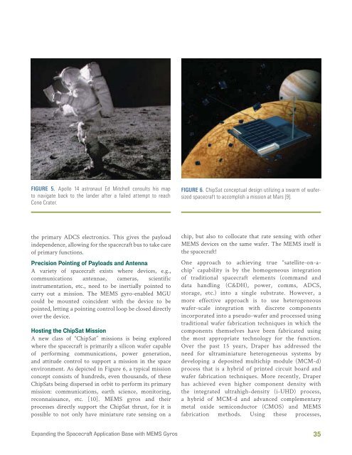
FIGURE 5. Apollo 14 astronaut Ed Mitchell consults his mapto navigate back to the lander after a failed attempt to reachCone Crater.FIGURE 6. ChipSat conceptual design utilizing a swarm of wafersizedspacecraft to accomplish a mission at Mars [9].the primary ADCS electronics. This gives the payloadindependence, allowing for the spacecraft bus to take careof primary functions.Precision Pointing of Payloads and AntennaA variety of spacecraft exists where devices, e.g.,communications antennae, cameras, scientificinstrumentation, etc., need to be inertially pointed tocarry out a mission. <strong>The</strong> MEMS gyro-enabled MGUcould be mounted coincident with the device to bepointed, letting a pointing control loop be closed directlyover the device.Hosting the ChipSat MissionA new class of “ChipSat” missions is being exploredwhere the spacecraft is primarily a silicon wafer capableof performing communications, power generation,and attitude control to support a mission in the spaceenvironment. As depicted in Figure 6, a typical missionconcept consists of hundreds, even thousands, of theseChipSats being dispersed in orbit to perform its primarymission: communications, earth science, monitoring,reconnaissance, etc. [10]. MEMS gyros and theirprocesses directly support the ChipSat thrust, for it ispossible to not only have miniature rate sensing on achip, but also to collocate that rate sensing with otherMEMS devices on the same wafer. <strong>The</strong> MEMS itself isthe spacecraft!One approach to achieving true “satellite-on-achip”capability is by the homogeneous integrationof traditional spacecraft elements (command anddata handling (C&DH), power, comms, ADCS,storage, etc.) into a single substrate. However, amore effective approach is to use heterogeneouswafer-scale integration with discrete componentsincorporated into a pseudo-wafer and processed usingtraditional wafer fabrication techniques in which thecomponents themselves have been fabricated usingthe most appropriate technology for the function.Over the past 15 years, <strong>Draper</strong> has addressed theneed for ultraminiature heterogeneous systems bydeveloping a deposited multichip module (MCM-d)process that is a hybrid of printed circuit board andwafer fabrication techniques. More recently, <strong>Draper</strong>has achieved even higher component density withthe integrated ultrahigh-density (i-UHD) process,a hybrid of MCM-d and advanced complementarymetal oxide semiconductor (CMOS) and MEMSfabrication methods. Using these processes,Expanding the Spacecraft Application Base with MEMS Gyros35
- Page 3: The Draper Technology Digest (CSDL-
- Page 11 and 12: AvionicsBolometerPIPayloadGPS Radio
- Page 13: HUMAN SPACE PROGRAMSApolloFrom the
- Page 18: System Cmd/ObjDescriptionScriptSour
- Page 21 and 22: HOW SMALL SPACE CAN ENABLEOPERATION
- Page 24 and 25: Science RequirementsThe primary per
- Page 26 and 27: The other end houses the payload, w
- Page 28: operations. For a thorough discussi
- Page 31: REFERENCES1. Mayor, M. and D. Quelo
- Page 35: TABLE 1. Space-Rated Gyro Compariso
- Page 40 and 41: Christopher M. Pong, Matthew W. Smi
- Page 43 and 44: SensorsActuatorsSoftware1-kHz Sampl
- Page 45: Adapter plateKistler tableFIGURE 6.
- Page 48: and actuators to measure and cancel
- Page 51 and 52: Given this linear system and assumi
- Page 55 and 56: REFERENCES1. Piterman, A. and Z. Ni
- Page 57 and 58: Office of the Chief Technologist pr
- Page 60 and 61: designer must balance the needs for
- Page 62 and 63: to select the type and number of sc
- Page 64: Small Space Authors’ BiographiesN
- Page 67 and 68: The 2011 Draper DistinguishedPerfor
- Page 69: performance, and vendor quality iss
- Page 74 and 75: RESULTSFigure 4 shows current volta
- Page 76 and 77: Authors’ BiographiesJonathan J. B
- Page 78: The 2011 EngineeringVice President
- Page 81 and 82: Sharon G. Kujawa, Ph.D., is an Asso
- Page 83 and 84: Jason FieringExcellence in Innovati
- Page 85 and 86: Peter CastelliOutstanding Task Lead
- Page 87 and 88:
Michael ClohecyOutstanding Task Lea
- Page 89:
Rick StonerHoward Musoff Student Me
- Page 92 and 93:
Deutsch, O.L.; Antelman, E.T.; Peli
- Page 94 and 95:
Kniazeva, T.; Hsiao, J.C.; Charest,
- Page 97 and 98:
Smith, M.W.; Seager, S.; Pong, C.M.
- Page 99 and 100:
List of 2011 Patents IssuedBarrows,
- Page 101:
Ko, C.W.; Supervisors: Tao, S.; Liv