designer must balance the needs for impact hardening(design of the electronics and mechanical systems),cost and mass of the deorbit rocket, and any system orscientific impacts that occur due to low impact angles. Aswill be seen in the subsequent sections, electronics impacthardness has been regularly demonstrated in the 20,000-g region, which is reasonably attainable for all but theshallowest impact depths, highest deployment altitudes,and lowest deorbit decelerations.Instrument DistributionA common thread in many planetary science missions isthe need to characterize the interior structure of the bodyin question. One of the most effective means to this end isto establish a network of geophysical instruments. <strong>The</strong>reare significant challenges to establishing such a networkon any remote planetary body. Geophysical observations,by their nature, need to be directly coupled with thesurface of the observed body. <strong>The</strong> individual stationmust operate for a long period of time, in a variety ofchallenging environments, and record high-quality data.<strong>The</strong>se have made the establishment of such a planetarynetwork cost prohibitive since the epoch of the Apollogeophysical experiments. <strong>The</strong> penetrator platform,particularly if focused for a subset of measurements,lends itself well to the geophysical network mission.To address the potential for penetrator attrition andto enhance overall mission reliability, a large numberof penetrators should be deployed to the target bodysurface. In order to do so, the mass of each penetratorand associated descent support system needs to be kept toa minimum. At the extreme, a single penetrator could beoptimized for a single science payload in order to reduceoverall support system mass (communication, power,processing). Science payloads can be distributed acrossthe entire network (i.e., X penetrators equipped withseismometers, Y penetrators equipped with heat flowsensors, etc.).APPLICABLE PENETRATOR TECHNOLOGYDEVELOPMENTAs discussed above, the UK Penetrator Consortiumbenefited from the presence of a defense contractor(QinetiQ) with experience in the design, implementation,and testing of high-g hardened systems. <strong>Draper</strong><strong>Laboratory</strong>’s experience with impact-hardenedelectronics and Microelectromechanical System (MEMS)instrumentation similarly enables viable penetratorbasedsensor networks. A few of these experiences andprograms are highlighted in the following sections.Impact-Hardened Packaging<strong>Draper</strong> has designed and implemented novel, highperformanceguidance systems for several differentguided munitions programs. <strong>The</strong>se systems must survivepunishing axial and centrifugal accelerations and continueto perform throughout the flight. <strong>The</strong>se systems includelow-cost designs using commercially available parts andcustom, low-power, low-volume designs.<strong>The</strong> Low-Cost Guidance Electronics Unit (LCGEU)program was successfully integrated and launched on theU.S. Navy Ballistic Trajectory Extended Range Munition(BTERM) and Ex-171 Extended Range Guided Munition(ERGM) projectiles. Its commercial-off-the-shelf (COTS)components include automotive-grade MEMS inertialinstruments, a Global Positioning System (GPS) receiver,GPS antijamming, processing, power conditioning, andinput/output electronics. <strong>The</strong>se were integrated intoa shock-mounted Inertial Sensor Assembly (ISA) toprevent vibration from degrading sensor performance.Figure 4 shows an exploded view of the LCGEU in the“stack of quarters” configuration. In all, the assembly is alittle over 3 inches in diameter and 3.5 inches tall, and iscapable of surviving over 18,000 g.PCE IOModuleProcessor ModuleAntijamElectronicsFIGURE 4. <strong>Draper</strong> LCGEU.GPS ReceiverInertial SensorAssembly<strong>The</strong> Competent Munitions Advanced <strong>Technology</strong>Demonstration (CMATD) program developed a lowvolume,low-power, impact-hardened control electronicspackage capable of withstanding a 20,000-g launch. <strong>The</strong>electronics included MEMS sensors and a crystal oscillatoras well as conventional passive and active components. <strong>The</strong>mechanical design included high-g capable housings for thevarious electronics and a spindle assembly that supportedthe guidance, navigation, and control (GN&C) section. Thisassembly was designed to survive a 15,000-rpm post-launchspin rate. <strong>The</strong> entire package, depicted in Figure 5, had avolume of approximately 3 in 3 and consumed 3 W.58 A Penetrator-Based Sensor Network for Planetary Geophysics
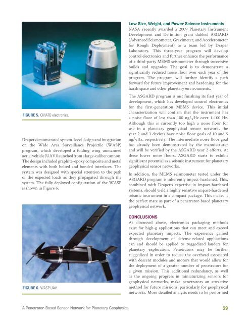
FIGURE 5. CMATD electronics.<strong>Draper</strong> demonstrated system-level design and integrationon the Wide Area Surveillance Projectile (WASP)program, which developed a folding wing unmannedaerial vehicle (UAV) launched from a large-caliber cannon.<strong>The</strong> design included graphite-epoxy composite and metalelements with both bolted and bonded interfaces. <strong>The</strong>system was designed with special attention to the pathof the expected loads as they propagated through thesystem. <strong>The</strong> fully deployed configuration of the WASPis shown in Figure 6.FIGURE 6. WASP UAV.Low Size, Weight, and Power Science InstrumentsNASA recently awarded a 2009 Planetary InstrumentDevelopment and Definition grant dubbed ASGARD(Advanced Seismometer, Gravimeter, and Accelerometerfor Rough Deployment) to a team led by <strong>Draper</strong><strong>Laboratory</strong>. This three-year program will developcontrol electronics and further enhance the performanceof a third-party MEMS seismometer through successivebuilds and upgrades. <strong>The</strong> goal is to demonstrate asignificantly reduced noise floor over each year of theprogram. <strong>The</strong> program will further identify a pathforward for future improvement and hardening for theharsh space and other planetary environments.<strong>The</strong> ASGARD program is just finishing its first year ofdevelopment, which has developed control electronicsfor the first-generation MEMS device. This initialcharacterization will confirm that the instrument hasa noise floor of less than 100 ng/√Hz over 1-100 Hz.Although this is currently too high a noise floor foruse in a planetary geophysical sensor network, theyear 2 and 3 devices have noise floor goals of 10 and 5ng/√Hz, respectively. <strong>The</strong> intermediate noise floor goalhas already been demonstrated by the manufacturerand will be verified by the ASGARD year 2 efforts. Atthese lower noise floors, ASGARD starts to exhibitsignificant potential as a seismic instrument for planetarygeophysical sensor networks.In addition, the MEMS seismometer tested under theASGARD program is inherently impact-hardened. This,combined with <strong>Draper</strong>’s expertise in impact-hardenedsystems, should yield a highly sensitive impact-hardenedseismic instrument in a compact package. This makes itthe perfect mate as part of a penetrator-based planetarygeophysical network.CONCLUSIONSAs discussed above, electronics packaging methodsexist for high-g applications that can meet and exceedexpected planetary impacts. <strong>The</strong> experience gainedthrough development of defense-related applicationscan and should be applied to ruggedized landers forplanetary exploration. Penetrators may be furtherruggedized in order to reduce the overhead associatedwith descent modules and motors that would allow forthe deployment of a greater number of penetrators fora given mission. This additional redundancy, as wellas the ongoing progress in miniaturizing sensors forgeophysical networks, make penetrators an attractivemethod for future missions, particularly for geophysicalnetworks. More detailed analysis needs to be performedA Penetrator-Based Sensor Network for Planetary Geophysics59
- Page 3:
The Draper Technology Digest (CSDL-
- Page 11 and 12: AvionicsBolometerPIPayloadGPS Radio
- Page 13: HUMAN SPACE PROGRAMSApolloFrom the
- Page 18: System Cmd/ObjDescriptionScriptSour
- Page 21 and 22: HOW SMALL SPACE CAN ENABLEOPERATION
- Page 24 and 25: Science RequirementsThe primary per
- Page 26 and 27: The other end houses the payload, w
- Page 28: operations. For a thorough discussi
- Page 31: REFERENCES1. Mayor, M. and D. Quelo
- Page 35 and 36: TABLE 1. Space-Rated Gyro Compariso
- Page 37 and 38: FIGURE 5. Apollo 14 astronaut Ed Mi
- Page 40 and 41: Christopher M. Pong, Matthew W. Smi
- Page 43 and 44: SensorsActuatorsSoftware1-kHz Sampl
- Page 45: Adapter plateKistler tableFIGURE 6.
- Page 48: and actuators to measure and cancel
- Page 51 and 52: Given this linear system and assumi
- Page 55 and 56: REFERENCES1. Piterman, A. and Z. Ni
- Page 57 and 58: Office of the Chief Technologist pr
- Page 62 and 63: to select the type and number of sc
- Page 64: Small Space Authors’ BiographiesN
- Page 67 and 68: The 2011 Draper DistinguishedPerfor
- Page 69: performance, and vendor quality iss
- Page 74 and 75: RESULTSFigure 4 shows current volta
- Page 76 and 77: Authors’ BiographiesJonathan J. B
- Page 78: The 2011 EngineeringVice President
- Page 81 and 82: Sharon G. Kujawa, Ph.D., is an Asso
- Page 83 and 84: Jason FieringExcellence in Innovati
- Page 85 and 86: Peter CastelliOutstanding Task Lead
- Page 87 and 88: Michael ClohecyOutstanding Task Lea
- Page 89: Rick StonerHoward Musoff Student Me
- Page 92 and 93: Deutsch, O.L.; Antelman, E.T.; Peli
- Page 94 and 95: Kniazeva, T.; Hsiao, J.C.; Charest,
- Page 97 and 98: Smith, M.W.; Seager, S.; Pong, C.M.
- Page 99 and 100: List of 2011 Patents IssuedBarrows,
- Page 101: Ko, C.W.; Supervisors: Tao, S.; Liv