

SSP337 The 2.0l FSI engine with turbocharger - VolksPage.Net
SSP337 The 2.0l FSI engine with turbocharger - VolksPage.Net
SSP337 The 2.0l FSI engine with turbocharger - VolksPage.Net

Create successful ePaper yourself
Turn your PDF publications into a flip-book with our unique Google optimized e-Paper software.
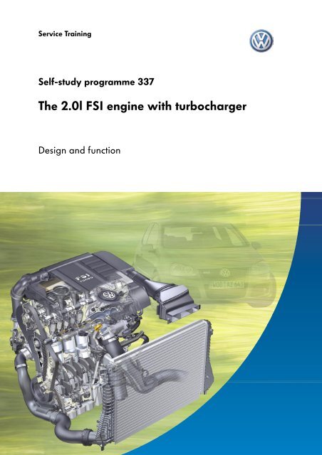
Service TrainingSelf-study programme 337<strong>The</strong> <strong>2.0l</strong> <strong>FSI</strong> <strong>engine</strong> <strong>with</strong> <strong>turbocharger</strong>Design and function
<strong>The</strong> new <strong>FSI</strong> <strong>engine</strong>s from Volkswagen do <strong>with</strong>out stratified injection and place greater emphasis onoutput and torque. Until now, <strong>FSI</strong> direct injection was always associated <strong>with</strong> stratification. On theturbocharged <strong>engine</strong>, the abbreviation <strong>FSI</strong> remains but there is no stratified charge.Doing <strong>with</strong>out fuel stratification and NOx sensors represents a loss on one part, but also promises thefinest driving enjoyment <strong>with</strong> high output and a torquey <strong>engine</strong> and great pulling power and economy.In this self-study programme you can familiarize yourself <strong>with</strong> the technical highlights of this <strong>engine</strong>.Further information can be found inself-study programme no. 322 -<strong>The</strong> <strong>2.0l</strong> <strong>FSI</strong> <strong>engine</strong> <strong>with</strong> 4-valvetechnology.S337_002NEWWarningNote<strong>The</strong> self-study programme shows the designand function of new developments.<strong>The</strong> contents will not be updated.For instructions on testing, adjusting and repairs,please refer to the relevant service literature.2
At a glanceIntroduction . . . . . . . . . . . . . . . . . . . . . . . . . . . . . . . . . . . . . . 4Engine mechanics . . . . . . . . . . . . . . . . . . . . . . . . . . . . . . . . . 6Engine management. . . . . . . . . . . . . . . . . . . . . . . . . . . . . . 12Service . . . . . . . . . . . . . . . . . . . . . . . . . . . . . . . . . . . . . . . . . 24Test your knowledge . . . . . . . . . . . . . . . . . . . . . . . . . . . . . . 263
IntroductionDescription of the <strong>engine</strong>In terms of basic dimensions and design, theturbo <strong>FSI</strong> <strong>engine</strong> is derived from the <strong>2.0l</strong> <strong>FSI</strong> <strong>with</strong><strong>engine</strong> code AXW.In order to meet the high expectations of aturbocharged <strong>engine</strong>, components of the <strong>engine</strong>had to be adapted to specific requirements.<strong>The</strong> exhaust manifold and the <strong>turbocharger</strong> formone unit.<strong>The</strong> exhaust and turbo module is customerservice friendly and is attached to the cylinderhead by a clamping flange.Exhaust manifoldSolenoid valve forcharge pressurecontrolN75TurbochargerResonancesilencerTurbocharger airrecirculation valve N249S337_003<strong>The</strong> crankshaft mechanics have been adapted tothe higher demands of a turbocharged <strong>FSI</strong><strong>engine</strong>.PistonConrodCrankshaftS337_0044
In order to meet the higher levels of power andheat transfer, the cylinder head has beenadapted to the specific conditions.<strong>The</strong> inlet camshaft features continuously variablevalve timing (adjustment range 42° crankshaftangle).Cylinder headInlet portsS337_005<strong>The</strong> optimised balancer shaft gear (AGW) isdriven by a decoupled drive chain sprocket.<strong>The</strong> function is similar to that of a dual massflywheel.Decoupled drive chainsprocketBalancer shaft gearS337_0065
Engine mechanicsTechnical data<strong>The</strong> <strong>2.0l</strong> turbocharged <strong>FSI</strong> <strong>engine</strong> was first installed in the Audi A3 Sportback. At Volkswagen, the <strong>engine</strong>finds its debut in the Golf GTI.Technical features- Turbocharger in exhaust manifold- Single pipe exhaust system <strong>with</strong> starter andunderbody catalyst close to <strong>engine</strong>- Hitachi high pressure pumpresistant to ethanol- Non-return fuel system- Homogenous fuel injectionTechnical dataEngine codeAXXEngine type4-cylinder in-line<strong>engine</strong>Capacity [mm 3 ] 1984Bore [mm] 82.5Stroke [mm] 92.8Compression ratio 10.5:1Max. output147 kW at 5700 rpmMax. torque280 Nmat 1800-4700 rpmEngine management Bosch Motronic MED 9.1Variable valve timing 42° crankshaft angleExhaust gasrecirculationFuelExhaust gas treatmentEmissions standard EU 4Inner exhaustgas recirculationPremium unleadedRON 98 (normalunleaded RON 95 <strong>with</strong>reducedperformance)2 three-way catalyticconverters<strong>with</strong> lambda controlTorque and performance graphTorque[Nm]S337_007Output[kW]Speed[rpm]S337_0086
<strong>The</strong> crankshaft<strong>The</strong> component strength was adapted to thehigher combustion pressures.<strong>The</strong> contact faces of the main journals andconrod journals were made larger to improvestrength.Engine block<strong>The</strong> cylinder contact surfaces of the cast iron<strong>engine</strong> block were honed by means of liquidblasting.Liquid blasting and smooth honing are anextension of the familiar two-stage honingtechnique by two additional process stages. Inthe first new processing stage, any compacting ofthe bushing contact surface brought about fromthe high pressure procedure is removed, andscores and damage from honing and cracks fromalloying are rectified. <strong>The</strong> resulting surface isthereby largely free of metallic imperfections. Inthe final honing operation, the rough edgesarising from blasting and any remaining roughareas are smoothed out to the highest level.This type of honing shortens the running-in timeof the <strong>engine</strong> and leads to lower oil consumption.Contact facesS337_009S337_010Modified pistons<strong>The</strong> piston crown of the T-<strong>FSI</strong> has been adaptedto the homogenous combustion procedure.<strong>2.0l</strong> 4V <strong>FSI</strong> <strong>2.0l</strong> 4V T-<strong>FSI</strong>S337_0117
Engine mechanics<strong>The</strong> balancer shaft gear<strong>The</strong> balancer shaft gear was taken over from thecommon <strong>FSI</strong> <strong>engine</strong>. However, it had to bemodified as follows:CrankshaftDrive gearBalancer wheelsBalancer shafthousing●●●●●●Decoupled drive chain sprocket in balancershaft mechanismSeparation of splines and compensationweights to increase balancing efficiencyOil pump <strong>with</strong> greater gear widthPressure relief valve, controlled purely by oil,<strong>with</strong> oil control in vicinity ofoil pump, integrated in balancer shaft housingStrength optimised pressure cast housingBearings of balancer shaftslocated directly in aluminium housingSuction lineBalancershaftsDrive chain sprocketOil pumpS337_012<strong>The</strong> decoupled drive chain sprocket<strong>The</strong> improved smooth running of the crankshaft in the lower speed range leads to a considerableincrease in chain forces in the balancer shaft gear. With a relative crankshaft vibration angle of 0.8° onthe normal <strong>FSI</strong> <strong>engine</strong>, the increased crankshaft vibration angle of 2° on the turbocharged <strong>FSI</strong> <strong>engine</strong> ismuch more noticeable. Due to the increased load of the chain drive, the chain would be subjected toincreased wear if there were no countermeasures. <strong>The</strong>refore, there are curved springs in the hub of thechain sprocket. <strong>The</strong>se decouple the input shaft of the balancer shaft gear to the crankshaft.Diamond washerHubFrictionbearingCurved springs(qty. 2)Chain sprocketFriction washerDished washerEnd washerS337_0138
<strong>The</strong> toothed belt drive mechanismAs <strong>with</strong> all 4-cylinder in-line <strong>engine</strong>s of series 113,the valve timing is designed as a toothed beltand direct exhaust camshaft drive system.Due to considerably higher demands on thetoothed belt drive mechanism, such as:●●●higher valve spring forces due to turboturbo-specific timing in conjunction <strong>with</strong>adjustment range of 42° CA from continuouslyvariable valve timing (inlet camshaft).high pressure pump drive by means of3 cams on inlet camshaft,the toothed belt tensioning system, adopted fromthe naturally aspirated <strong>engine</strong>, was modified.This resulted in an elliptical toothed belt pulley onthe crankshaft.<strong>The</strong> CTC toothed belt pulley*, used for the firsttime, reduces rotational vibrations on thecamshaft and pulling forces on the toothed belt.Function<strong>The</strong> positioning of the toothed belt on thecrankshaft is shown at TDC no. 1 cylinder, as inillustration 337_014. Once the working strokebegins, extremely high pulling forces areimparted on the toothed belt. <strong>The</strong>se are reducedby the elliptical shape of the toothed belt pulley,due to the fact that the flat side of the pulleyallows slight detensioning of the toothed belt. <strong>The</strong>rotational vibrations that arise as a resultcounteract the rotational vibrations of the 2nd<strong>engine</strong> order in the resonance point of the timingmechanism, <strong>with</strong>out causing excessive unrest inother speed ranges.* CTC toothed belt pulley = Crankshaft Torsionals CancellationS337_0149
Engine mechanics<strong>The</strong> cylinder headTurbo-specific changes were made to thecylinder head (<strong>with</strong> regards to the <strong>2.0l</strong> <strong>FSI</strong>):●●●●Sodium filled exhaust valvesArmoured inlet and exhaust valve seatsStrength-optimised roller rocker fingers <strong>with</strong>reduction in web width from cams and rollersValve springs <strong>with</strong> increased spring forces(same valve springs for inlet and exhaustvalves)Furthermore, the inlet port geometry wasmodified. This enabled the tumble effect andthereby the knock resistance and smooth runningproperties to be improved.<strong>2.0l</strong> 4V <strong>FSI</strong> <strong>2.0l</strong> 4V T-<strong>FSI</strong>S337_015S337_01610
<strong>The</strong> crankcase breather system<strong>The</strong> constant vacuum in the crankcase is assuredby a separate breather system for crankcase andcylinder head.<strong>The</strong> blow-by gases emerging from the crankcaseare passed via the primary oil separator in the oilfilter module to the cylinder head cover.When this happens, the blow-by gases aremixed <strong>with</strong> those from the cylinder head and arepassed through a labyrinth, where further oilseparation occurs.Since turbo operation requires more complicatedpressure control, there is a two-stage pressurerelief valve on the cylinder head cover, whichchannels the blow-by gases to the intakemanifold or <strong>turbocharger</strong>. When there is vacuumin the intake manifold, the blow-by gases are feddirectly to the intake manifold.In the case of charge pressure, a non-returnvalve closes in the pressure relief valve housing.<strong>The</strong> blow-by gases are fed to the <strong>turbocharger</strong>via a channel in the cylinder head cover. Torecognize an incorrectly installed pressure reliefvalve, a so-called diagnosis port has beenintegrated. Incorrect installation forcesunmetered air via the sealing area of thepressure relief valve into the cylinder head cover.<strong>The</strong> reaction of the lambda probe results indiagnosis of the unmetered air and a fault is thenstored in the memory.With charge pressure before <strong>turbocharger</strong>With vacuum to intake manifoldGas outlet to <strong>turbocharger</strong>Labyrinth in cylinder head coverGas outlet tointakemanifoldPrimary oilseparatorOil filter moduleNon-return lockingvalvePressure reliefvalveDiagnosischannelNon-return lockingvalveS337_01711
Engine management<strong>The</strong> <strong>turbocharger</strong>/exhaust manifold moduleTo save space, an exhaust manifold/<strong>turbocharger</strong> housing was developed, which can be installed <strong>with</strong>all <strong>engine</strong> variations in longitudinal or transverse configuration. Importance was also placed on realisinga customer service orientated solution to allow the exhaust manifold to be removed and installed easily,and for a catalytic converter to be included close to the <strong>engine</strong>.Crankcase breatherconnectionCoolant flow to radiatorand from auxiliary waterpumpActive charcoal filterconnectionPressurised oil supplyTurbocharger airrecirculation valve N249Oil returnCoolant supply to <strong>engine</strong>blockS337_018<strong>The</strong> bearing of the turbine shaft is integrated in the compressor housing. <strong>The</strong> cylinder head cover housesthe crankcase and active charcoal breather connections. Screwed into the pressure connection is anindividually tuned resonance silencer to reduce the pressure pulsation noises.<strong>The</strong> required charge pressure is adjusted via the charge pressure control solenoid valve N75 (pressurerelief control as on 1.8 l turbocharged <strong>engine</strong>) and the so-called wastegate.<strong>The</strong> charge pressure control solenoid valve N75 and the <strong>turbocharger</strong> air recirculation valve N249 canbe found on the <strong>turbocharger</strong>.12
<strong>The</strong> <strong>turbocharger</strong> <strong>with</strong> new flange fixture<strong>The</strong> <strong>turbocharger</strong> module is easy to fit and is attached to the cylinder head by five threaded connections.For removal and installation, the clamping strip need not be loosened.<strong>The</strong> exhaust manifold is designed to take advantage of the firing order. <strong>The</strong> manifold is fluted to channelthe exhaust gases equally over the turbine. In this way, the exhaust ports are separated in line <strong>with</strong> thefiring order. Furthermore, the flute channel prevents the exhaust gas pressure from expanding into othercylinder ports.This means that the required turbine speed is maintained and the response of the <strong>turbocharger</strong> could beoptimised.Flute channelClamping stripS337_01913
Engine managementCharge pressure flow and charge pressure controlControl pressure is formed from the chargepressure and intake pressure via the energisedcharge pressure control solenoid valve N75. <strong>The</strong>control pressure affects the vacuum unit, whichactuates the wastegate valve via a linkage. <strong>The</strong>wastegate valve opens a bypass channel toallow part of the exhaust gases past the turbineinto the exhaust gas system. This control featureallows the speed of the turbine to be controlledand the maximum charge pressure can therebybe regulated.If the control features fails, the vacuumunit is affected directly by the chargepressure, which imparts pressureagainst the spring. <strong>The</strong> maximumcharge pressure is thereby restricted toa basic operating charge pressure.Turbocharger air recirculation valve N249Charge pressure controlsolenoid valve N75WastegateVacuum unitCharge air coolerS337_02014
<strong>The</strong> electric overrun air recirculation control (previously pneumatic)In order to prevent the <strong>turbocharger</strong> from braking too heavily in overrun and between gear changes, anelectric <strong>turbocharger</strong> air recirculation valve N249 is installed.<strong>The</strong> electric overrun air recirculation control is much more durable than the pneumatic one.In overrun, the vacuum unit is completely closed. <strong>The</strong> overrun air recirculation control is open, evenbetween gear changes.During overrun, pressure is built up in the compressor housing due to the prevailing charge pressure. Thispressure build-up causes the compressor wheel to brake heavily, which leads to a reduction in theprevailing charge pressure (turbo drop). To prevent this from happening, the <strong>turbocharger</strong> airrecirculation valve N249 is opened by an electric servomotor. It opens a bypass channel to passcompressed air via the compressor wheel back to the suction side of the compressor circuit. This keepsthe turbine at a constant speed. When the throttle valve is opened, the <strong>turbocharger</strong> air recirculationvalve N249 is closed and charge pressure is immediately available again.OverrunAir intakefrom air cleanerUnder loadOverrun air recirculationvalve openOverrun airrecirculationvalveclosedS337_02715
Engine management<strong>The</strong> cooling system <strong>with</strong> coolant run-on pump and radiator run-onTo prevent oil deposits from burning onto the turbine shaft in the <strong>turbocharger</strong>, an auxiliary water pumpruns-on for up to 15 minutes after the <strong>engine</strong> has been switched off. It transports the cooler coolantagainst the direction of normal flow. As it does this, coolant drawn in from the auxiliary pump flows fromthe radiator via the <strong>turbocharger</strong> in the <strong>engine</strong> block and back to the radiator to break down the residualheat.Connection on<strong>turbocharger</strong>Engine block connectionAuxiliary water pump operationEngine operationEngine operationAuxiliary water pumpoperationRadiator outletAuxiliary water pumpRadiator inletS337_02116
<strong>The</strong> tumble flapsSince the <strong>engine</strong> is operated in homogenous mode, the tumble flaps are used to improve the internalmixture formation.At low loads, in a speed range from 1000 rpm to5000 rpm, the tumble flaps are closed:Torque[Nm]Output[kW]- to improve idling speed quality on acold <strong>engine</strong>- to increase the tumble effect and therebyimprove smooth running of the <strong>engine</strong>- in overrun to prevent <strong>engine</strong> joltsIn other speed ranges, the tumble flaps are opento avoid any resistance to flow and thereby areduction in performance.Range in which tumble flaps are closed.Speed[rpm]S337_022Tumble flap <strong>with</strong>steel shaftCoupling rodThrottle valve moduleIntake manifold flap motorV157 <strong>with</strong> intake manifoldflap potentiometer G336S337_02317
Engine management<strong>The</strong> fuel supply<strong>The</strong> direct injection petrol <strong>engine</strong>s are supplied <strong>with</strong> fuel via a demand-controlled fuel pump. Thisdemand-control feature was developed to bring the energy requirement of the fuel pump to a low leveland thereby to save fuel.To achieve increasingly high pressures, the pump is driven by 3 cams (2 cams on AXW).<strong>The</strong> electric fuel pump provides just the amount of fuel required by the <strong>engine</strong> at a prescribed systempressure. This is controlled by the <strong>engine</strong> control unit and an electronic system that regulates the speed ofthe fuel pump via pulse width modulation.Fuel pressure regulating valve N276High pressurefuel pumpPump cams (qty. 3)High pressure injectorLow pressure fuel circuitFuel pressuresender for lowpressure G410Pressure limitation valveHigh pressure fuel circuitFuel pressure sender G247S337_02418
Modes of operation<strong>The</strong> turbocharged <strong>engine</strong> is driven in two modes of operation.Dual injection <strong>with</strong> cold startDual injection is a special mode of operation for rapid heating of the catalytic converter.To do this, a quantity of fuel is injected on the intake stroke at approx 300° before TDC of ignition. <strong>The</strong>fuel distributes itself homogeneously due to the long gap before ignition. <strong>The</strong> second injection occurs atapprox. 60° before TDC of ignition in the compression phase.<strong>The</strong> rich mixture that thereby forms around the spark plug means that timing can be retarded to aconsiderable degree <strong>with</strong>out affecting stability of the <strong>engine</strong>.Both injection periods result in lambda 1. Since the exhaust valves are already open, the exhaust gastemperature rises rapidly. This brings the catalytic converter to operating temperature (350°C) in a shortspace of time (30-40 seconds).When the driver door is opened, the electric fuel pump is energised by means of the door contact switch.<strong>The</strong> prestart serves as a means of shortening the start time and to build-up pressure more rapidly.A maximum counter is installed to prevent the pump from becoming damaged.Main mode of operation <strong>with</strong> catalytic converter at operating temperatureOnly homogenous injection occurs in the area of the spark plugs, as no additional heating of thecatalytic converter is necessary.<strong>The</strong> <strong>engine</strong> sets to lambda 1.To prevent heat bubbles forming in the fuel line, the electric fuel pump is actuated even when the <strong>engine</strong>is at operating temperature.19
Engine management<strong>The</strong> system overviewG70 Air mass meterG31 Charge pressure senderG42 Intake air temperature senderG28 Engine speed senderT16Diagnosis interfaceG40 Hall senderJ220 Motronic control unitJ338 Throttle valve moduleG187 Throttle valve drive anglesender 1 for EPCG188 Throttle valve drive anglesender 2 for EPCG79 Accelerator pedal position senderG185 Accelerator pedal position sender 2FF47Brake light switchBrake pedal switchG247 Fuel pressure senderG336 Intake manifold flap potentiometerG61 Knock sensor 1G66 Knock sensor 2G62 Coolant temperature senderG83Coolant temperature sender atradiator outletG410 Fuel pressure sender for low pressureG42 Intake air temperature senderG39 Lambda probeG130 Lambda probe after catalytic converterCOM leadCAN driveG476 Clutch position senderAlternator DFCCS on/offJ519J533Onboard supply ctrl unitDiagnosis interfacefor data bus20
J538Control unit forfuel pumpGG6Fuel gauge senderFuel system pressurisation pumpN30 - N33Injectors for cylinders no. 1 - 4N70 Ignition coil 1 <strong>with</strong> final output stageN127 Ignition coil 2 <strong>with</strong> final output stageN291 Ignition coil 3 <strong>with</strong> final output stageN292 Ignition coil 4 <strong>with</strong> final output stageJ338 Throttle valve moduleG186 Throttle valve drive for electronicpower controlJ317 Voltage supply relay term.30J757 Voltage supply relay for<strong>engine</strong> componentsJ329 Term. 15 voltage supply relayN80 Active charcoal relay solenoid valve 1N276 Fuel pressure control valveV157 Intake manifold flap motorJ285J527J104Control unit indash panel insertControl unit forsteering columnelectronicsControl unit forABSN205Inlet camshaft control valve 1N75Charge pressure control solenoid valveN249 Turbocharger air recirculation valveZ19Z29Lambda probe heatingLambda probe 1 heater aftercatalytic converterJ235 Coolant pump relayV50Coolant circulation pumpJ293 Radiator fan control unit (PWM)S337_02621
Engine managementFunctional diagramA BatteryF Brake light switchF47 Brake pedal switchG Fuel gauge senderG1 Fuel gaugeG6 Fuel pumpG28 Engine speed senderG31 Charge pressure senderG39 Lambda probeG40 Hall senderG42 Intake air temperature senderG61 Knock sensor 1G62 Coolant temperature senderG66 Knock sensor 2G70 Air mass meterG79 Accelerator pedal position senderG83 Coolant temperature sender at radiator outletG130 Lambda probe after catalytic converterG185 Accelerator pedal position sender 2G186 Throttle valve drive for electronicpower controlG187 Throttle valve drive angle sender 1 forelectronic power controlG188 Throttle valve drive angle sender 2 forelectronic power controlG247 Fuel pressure senderColour coding/keyOutput signalEarthInput signalPositiveCAN drive train22
G336 Intake manifold flap potentiometerG410 Fuel pressure sender for low pressureG476 Clutch position senderJ220 Motronic control unitJ235 Coolant pump relayJ285 Control unit in dash panel insertJ317 Term. 30 voltage supply relayJ329 Term. 15 voltage supply relayJ338 Throttle valve moduleJ519 Onboard supply control unitJ533 Data bus diagnosis interfaceJ538 Control unit for fuel pumpJ682 Term. 50 voltage supply relayJ757 Voltage supply relay for <strong>engine</strong> componentsN30 Injector for cylinder no. 1N31 Injector for cylinder no. 2N32 Injector for cylinder no. 3N33 Injector for cylinder no. 4S337_025N70 Ignition coil 1 <strong>with</strong> final output stageN75 Charge pressure control solenoid valveN80 Active charcoal filter system solenoid valve 1N127 Ignition coil 2 <strong>with</strong> final output stageN205 Inlet camshaft control valve 1N249 Turbocharger air recirculation valveN276 Fuel pressure control valveN291 Ignition coil 3 <strong>with</strong> final output stageN292 Ignition coil 4 <strong>with</strong> final output stageP Spark plug connectorQ Spark plugsS FuseT16 Diagnosis interfaceV50 Coolant circulation pumpV157 Intake manifold flap motorZ19 Lambda probe heatingZ29 Lambda probe 1 heater after catalytic converter23
ServiceSpecial toolsDesignation Tool ApplicationT10252Camshaft barTo lock camshaft in order toremove pulleyVAG 1687Charge air systemtesterTo check for leaks in charge airsystemWith new adapter1687/524
Special toolsDesignation Tool ApplicationT10133<strong>FSI</strong> special toolcaseCommon special tools for repairsto <strong>FSI</strong> <strong>engine</strong>s. Also used onturbocharged <strong>FSI</strong> <strong>engine</strong>.T40057Oil drain adapterTo drain <strong>engine</strong> oil from oil filterhousingT40001PullerTo pull off camshaft pulleyT40001/1 - 7Arms for puller25
Test your knowledge1. In which mode of operation is the T-<strong>FSI</strong> driven? a) Homogeneous mode b) Homogeneous lean mode c) Stratified mode2. When are the tumble flaps actuated?3. Where is the elliptical CTC toothed belt pulley used? a) Variable valve timing b) Balancer shaft drive c) Toothed belt drive4. <strong>The</strong> flute channel in the exhaust manifold has the following tasks a) Equal flow of exhaust gases to <strong>turbocharger</strong> b) Prevents back flow of exhaust gases c) Turbocharger speed is maintained d) Response of <strong>turbocharger</strong> is optimisedAnswers:1. a 2. At low load in a speed range of 1000 - 5000 rpm3. c 4. a, b, c, d26
Notes27
337For internal use only © VOLKSWAGEN AG, WolfsburgAll rights reserved, including the right to make technical changes000.2811.52.20 Technical status 12/04❀ This paper was made fromchlorine-free pulp.


