

Decoupling Capacitor Connection Inductance - IEEE EMC Society
Decoupling Capacitor Connection Inductance - IEEE EMC Society
Decoupling Capacitor Connection Inductance - IEEE EMC Society

Create successful ePaper yourself
Turn your PDF publications into a flip-book with our unique Google optimized e-Paper software.
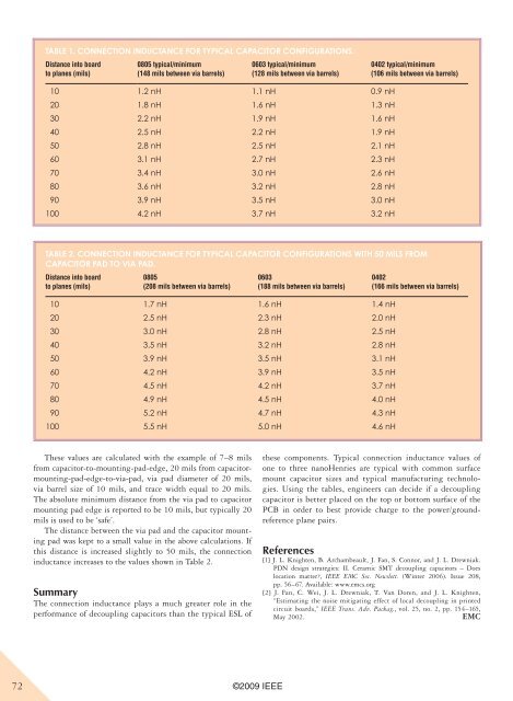
Table 1. <strong>Connection</strong> <strong>Inductance</strong> for Typical <strong>Capacitor</strong> Configurations.Distance into boardto planes (mils)0805 typical/minimum(148 mils between via barrels)0603 typical/minimum(128 mils between via barrels)0402 typical/minimum(106 mils between via barrels)10 1.2 nH 1.1 nH 0.9 nH20 1.8 nH 1.6 nH 1.3 nH30 2.2 nH 1.9 nH 1.6 nH40 2.5 nH 2.2 nH 1.9 nH50 2.8 nH 2.5 nH 2.1 nH60 3.1 nH 2.7 nH 2.3 nH70 3.4 nH 3.0 nH 2.6 nH80 3.6 nH 3.2 nH 2.8 nH90 3.9 nH 3.5 nH 3.0 nH100 4.2 nH 3.7 nH 3.2 nHTable 2. <strong>Connection</strong> <strong>Inductance</strong> for Typical <strong>Capacitor</strong> Configurations with 50 mils from<strong>Capacitor</strong> Pad to Via Pad.Distance into boardto planes (mils)0805(208 mils between via barrels)0603(188 mils between via barrels)10 1.7 nH 1.6 nH 1.4 nH20 2.5 nH 2.3 nH 2.0 nH30 3.0 nH 2.8 nH 2.5 nH40 3.5 nH 3.2 nH 2.8 nH50 3.9 nH 3.5 nH 3.1 nH60 4.2 nH 3.9 nH 3.5 nH70 4.5 nH 4.2 nH 3.7 nH80 4.9 nH 4.5 nH 4.0 nH90 5.2 nH 4.7 nH 4.3 nH100 5.5 nH 5.0 nH 4.6 nH0402(166 mils between via barrels)These values are calculated with the example of 7–8 milsfrom capacitor-to-mounting-pad-edge, 20 mils from capacitormounting-pad-edge-to-via-pad,via pad diameter of 20 mils,via barrel size of 10 mils, and trace width equal to 20 mils.The absolute minimum distance from the via pad to capacitormounting pad edge is reported to be 10 mils, but typically 20mils is used to be ‘safe’.The distance between the via pad and the capacitor mountingpad was kept to a small value in the above calculations. Ifthis distance is increased slightly to 50 mils, the connectioninductance increases to the values shown in Table 2.SummaryThe connection inductance plays a much greater role in theperformance of decoupling capacitors than the typical ESL ofthese components. Typical connection inductance values ofone to three nanoHenries are typical with common surfacemount capacitor sizes and typical manufacturing technologies.Using the tables, engineers can decide if a decouplingcapacitor is better placed on the top or bottom surface of thePCB in order to best provide charge to the power/groundreferenceplane pairs.References[1] J. L. Knighten, B. Archambeault, J. Fan, S. Connor, and J. L. Drewniak.PDN design strategies: II. Ceramic SMT decoupling capacitors – Doeslocation matter?, <strong>IEEE</strong> <strong>EMC</strong> Soc. Newslett. (Winter 2006). Issue 208,pp. 56–67. Available: www.emcs.org[2] J. Fan, C. Wei, J. L. Drewniak, T. Van Doren, and J. L. Knighten,“Estimating the noise mitigating effect of local decoupling in printedcircuit boards,” <strong>IEEE</strong> Trans. Adv. Packag., vol. 25, no. 2, pp. 154–165,May 2002.<strong>EMC</strong>72 ©2009 <strong>IEEE</strong>


