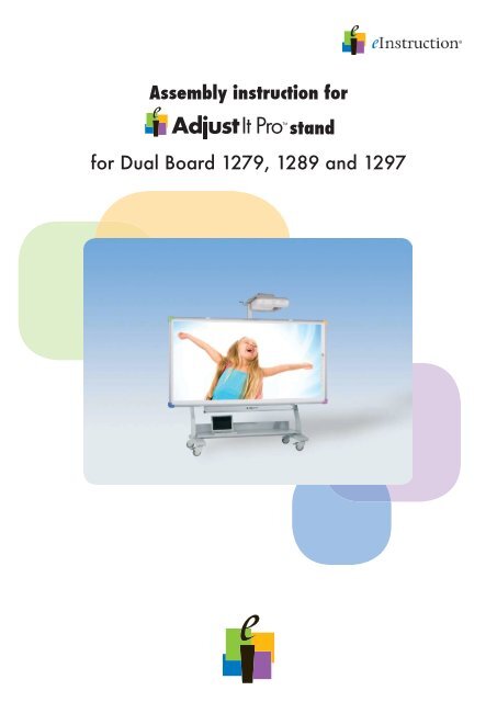
Assembly instruction for stand for Dual Board 1279 ... - eInstruction
Assembly instruction for stand for Dual Board 1279 ... - eInstruction
Assembly instruction for stand for Dual Board 1279 ... - eInstruction

Create successful ePaper yourself
Turn your PDF publications into a flip-book with our unique Google optimized e-Paper software.
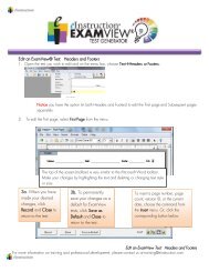
Be<strong>for</strong>e installation – SKU explanationPicture:description:`G3` board framewith integrated FIXED projector arm supportto accommodate third party wall mount armsor to accommodate G3-AP-G1G projector armpart number:IW-A-118-075-002-R`G3` long projector arm with universal mountto accommodate short throw projectors withmax. 4 ft. throw distanceIW-A-118-075-013-RMobile <strong>stand</strong>IW-A-118-075-005-RNotebook shelf (optional)IW-A-118-075-014-R6<strong>Assembly</strong> <strong>instruction</strong> <strong>for</strong> AdjustIt Pro <strong>stand</strong>
<strong>Assembly</strong> of height adjustable mount – NHV-G21. Unpack spring mechanism and G2 frame2. Attach board frame to the spring mechanismusing 4x M8 Allen head screws, washersand bolts<strong>Assembly</strong> of height adjustable mount – NHV-G31. Unpack spring mechanism and G3 frame2. Attach board frame to the spring mech.using 4x M8 Allen head screws, washersand bolts10<strong>Assembly</strong> <strong>instruction</strong> <strong>for</strong> AdjustIt Pro <strong>stand</strong>
Attaching the mount to the wall1.400 mm1.400 mm1.300 mm277 mm277 mmFloor1. Mark the position of the 4 holes on the wall:- lower holes at appr. 51“ from the floor- lateral distance between the holes: 55.1“- vertical distance between holes: 19.1“2. Drill the holes, using a 12mm drill3. Fix the mount to the wall, using the correcthardwareMounting hardware <strong>for</strong> wall mounting is NOT included.It´s the responsibility of the installer to verify compliance with all local building codes andto ensure that the supporting wall surface will safely support the combined load of allequipment and that the proper mounting hardware is being used.11<strong>Assembly</strong> <strong>instruction</strong> <strong>for</strong> AdjustIt Pro <strong>stand</strong>
Attaching the mount to the mobile <strong>stand</strong>1. Choose the mounting height:The mobile <strong>stand</strong> allows <strong>for</strong> the mountto be at tached in 3 different heights.Low position: use the lowest position(3rd and 6th hole) if clearance of lowestdoor is less than 77.5“ / 195cm or <strong>for</strong>applications in Kindergarten or Primaryeducation where lower board heightsare required.High position: if clearance is greater than77.5“ / 195cm and <strong>for</strong> applicationswhere higher board heights are prefered.2. Put the M8x80 screws in the desired upperholes from the back side of the frame.Useone washer under each bolt head.3. Tape the screws to the frame. This willmake it easier to attach the mount to the<strong>stand</strong>.4. Place the mount onto the <strong>stand</strong> andsecure the mount with one M8 washerand M8 nut per screw.12<strong>Assembly</strong> <strong>instruction</strong> <strong>for</strong> AdjustIt Pro <strong>stand</strong>
Securing the spring tensionSecuring the spring tension mechanism to the lowest positionCAUTIONThe springs in the height adjustable unit can store a large amount of energy;use care when assembling, installing and adjusting.DO NOT remove the locking pin to raise the assembly without first installing the boardand projectorFollow all installation <strong>instruction</strong>s when setting tension and adjusting height of assembly.Failure to place system in equilibrium prior to pin removal could result in serious personalinjury.The spring tension mechanism should be secured in its lowest position be<strong>for</strong>e proceeding withthe installation of board and projector.Two people are required to per<strong>for</strong>m this step.To secure the spring tension mechanism to the lowest position:1. pull the mechanism down. Use caution;the spring mechanism stores a largeamountof energy. If suddenly released,the moving carriage could inflict personalinjury.2. Have a second person secure the system inits lowest position by inserting the retentionpin. The retention pin fits in the „throughand-through“hole of the vertical tube.After inserting pin, roll clip around thevertical tube to secure.13<strong>Assembly</strong> <strong>instruction</strong> <strong>for</strong> AdjustIt Pro <strong>stand</strong>
Installing the G2 projector post (applies only <strong>for</strong> mounts with G2 board frame)PostProjector arm supportTo install the G2 post:1. Remove the M10 bolts, which will be usedafter assembly to secure the arm in theprojection position.2. Slide the projector post into the projectorarm support3. Select one of the 7 available mountingpositions, considering the available roomheight and door clearance, and secure thepost with the M10 hexagon head screws.14<strong>Assembly</strong> <strong>instruction</strong> <strong>for</strong> AdjustIt Pro <strong>stand</strong>
Installing the projector mount to NHV-G2 projector post1. Mount the projector to the projector mount(see assembly <strong>instruction</strong> projector mount)2. Temporarily loosen the knurled head screwand remove the 2 Allen head screwson the projector postAttachAttachprojectorprojectorandandmountmounttotothetheNHV-G2SNHV-G2SAttach projector and mount to the NHV-G2SvvvAttachAttachthetheprojectorprojectorarmarmandandmountmounttotothethesystem.Attach system.Adjustthe projector Adjustthearm theprojector.and projector.Finallymount to Finallyfixthe fixthethehandwheel.system. handwheel. Adjust the projector. Finally fix thehandwheel.3. Slide the mount underneath theknurled head screw and washerand secure it.4. Secure the mount by reinstalling andtightening the Allen head screws5. Use the crank at the projector arm toadjust the height of the projector.To swing the projector, to be able to move thesystem ToTo through swingswingthe a the door projector,projector, loosen the toto handwheel bebeableabletoto at movemovethethethe top systemsystem of the through mount through a a little. adoordoor Remove loosenloosen the thethehandwheelhandwheelatathandwheel the at the bottom side of the mount.thetoptopofofthethemountmountaalittle.little.RemoveRemovethethehandwheelhandwheelatatthethebottombottomsidesideofofthethemount.mount.6. Use the two socket head jack screwsto adjust the side-to-side tilt of the projector.Tightening the right screw raises the rightside of the projector and tightening the leftscrew raises the left side of the projector.You can now push the mount sideward. Do nottouch the projector while moving the mount in7. If, in case of a mobile application, theprojector needs to be pushed sideways toallow <strong>for</strong> the <strong>stand</strong> to fit through a dooropening, loosen the knurled head screwat the bottom of the mount and push themount and projector parallel to the board.order You not to readjust the picture by accident. Fixthe projector Youcancannowin nowpushthe new pushtheposition themountmountsideward.by using sideward.Dothe Donotnottouchhandwheel touchtheon theprojectortop projectorwhileof the mount. whilemovingAfter movingthehaving themountmountininorderpassed ordernotthe door, nottotoreadjustyou readjustthecan move thepicturethe picturebyprojector byaccident.accident.FixFixback the to the operating projectorprojector position. ininthethe Attach newnewpositionposition the handwheel bybyusingusingthetheat the handwheelhandwheel bottom side onon of top the top mount ofofthethe again. mount.mount. You AfterAfter do havinghavingnot have passedpassedto adjust thethedoor,door,the picture youyoucancannew. movemovethetheprojectorprojectorbackbacktotooperatingoperatingposition.position.AttachAttachthethehandwheelhandwheelatatthethebottombottomsidesideofofthethemountmountagain.again.YouYoudodonotnothavehavetotoadjustadjustthethepicturepicturenew.new.8. At the place of presentation reposition themount and projector in its initial positionand secure the knurled head screw.16<strong>Assembly</strong> <strong>instruction</strong> <strong>for</strong> AdjustIt Pro <strong>stand</strong>
Adjusting the spring tensionDuring installation, the spring-tension mechanism is secured in its lowest position.After installation is complete and both board and projector have been mountedthe mount has to be balanced to the total weight of the configuration.To balance the system the spring tension needs to be adjusted.CAUTIONThe springs in the height adjustable unit can store a large amount of energy;use care when assembling, installing and adjusting.DO NOT remove the locking pin to raise the assembly without first installing the boardand projectorBe<strong>for</strong>e adjusting the spring tension:1. apply downward <strong>for</strong>ce to the board2. release the locking pin3. release the board slowlyIf the board comes down, spring tension has to be increased,if the board starts moving up, spring tension has to be decreased.This is accomplished by using a 17 mm ratchet to turn the screw located on the right handside of the spring-ension mechanism. Turn clockwise to increase the tension,turn counter-clockwise to decrease the tension.Adjust tension such that the board stays in the same position when moved up/down andreleased and such that the system moves up and down with little operator ef<strong>for</strong>t.17<strong>Assembly</strong> <strong>instruction</strong> <strong>for</strong> AdjustIt Pro <strong>stand</strong>