Trane Modular Variable Speed Air Handlers Convertible Variable ...
Trane Modular Variable Speed Air Handlers Convertible Variable ...
Trane Modular Variable Speed Air Handlers Convertible Variable ...

Create successful ePaper yourself
Turn your PDF publications into a flip-book with our unique Google optimized e-Paper software.
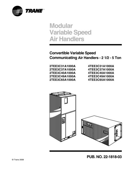
<strong>Modular</strong><strong>Variable</strong> <strong>Speed</strong><strong>Air</strong> <strong>Handlers</strong><strong>Convertible</strong> <strong>Variable</strong> <strong>Speed</strong>Communicating <strong>Air</strong> <strong>Handlers</strong> - 2 1/2 - 5 Ton2TEE3C31A1000A2TEE3C37A1000A2TEE3C40A1000A2TEE3C49A1000A2TEE3C65A1000A4TEE3C31A1000A4TEE3C37A1000A4TEE3C40A1000A4TEE3C49A1000A4TEE3C65A1000A© <strong>Trane</strong> 2008PUB. NO. 22-1818-03
Featuresand Benefits• Ships vertical - converts to horizontalby laying unit on side.• Six-way convertibility – horizontal(left & right), front & rear access;upflow, downflow• Electrical, refrigerant, condensate &blower access convertible to eitherside• Compact 21" depth for easy installation• <strong>Variable</strong> speed ECM motor• Direct drive blower• Comfort-R enhanced dehumidificationcycle• Soft Start - On cycle fan speed is increasedgradually to reduce soundand drafts• Corrosion resistant galvanized metalwith attractive finish• Non-bleed Expansion valve• Check valve for heat pump application• Internally enhanced finned coil tubing• External brazed refrigerant connections• 200/230 volt primary & 24 voltsecondary transformer• Low voltage terminal board• Uses 1400 series heaters• Access to heater circuit breakers• Polarized plugs for making motorand transformer electrical connectionsfrom air handler control box toelectric heaters• Primary and secondary drain connections• Easy <strong>Air</strong>-Tite TM access to coils• Built-in indoor fan delay function forincreased efficiency• 2/4TEE3C31 airflow selectable for1-1/2 — 3 ton O.D. unit• 2/4TEE3C37, 2/4TEE3C40 airflowselectable for 2 — 3-1/2 ton O.D.unit• 2/4TEE3C49 airflow selectable for3 — 5 ton O.D. unit• 2/4TEE3C65 airflow selectable for3 — 5 ton O.D. unit• Energy-saving continuous fan• Enhanced cooling/heating control• ComfortLink TM II 3-wire connectivityor 24 volt connection.Optional EquipmentOPTIONAL EQUIPMENT FOR AIR HANDLERS (Check mark [✓] indicates accessories included).Plenum - Pedestal (2/4TEE3C37, 40, 49, 65) ......................................................................................... TAYPLNM100 [ ]Sub-base For Downflow (2/4TEE3C31) ................................................................................................... TAYBASE101 [ ]Sub-base For Downflow (2/4TEE3C37) ................................................................................................... TAYBASE100 [ ]Sub-base For Downflow (2/4TEE3C40, 49, 65) ....................................................................................... TAYBASE102 [ ]Evaporator Defrost Control Kit - Cooling Units (Low Ambient Cooling) ..........................................................AY28X079 [ ]Evaporator Defrost Control Kit - Heat Pumps (Low Ambient Cooling) ............................................................AY28X084 [ ]Knockout cover plate (2/4TEE3C31, 37, 40, 49, 65) .................................................................................. BAY99X123 [ ]Humidistat .............................................................................................................................................. BAYSTAT253 [ ]Plenum For Upflow Non-Ducted Applications (2/4TEE3C31, 37, 40, 49, 65) ........................................... BAYPLNM120 [ ]© 2008 <strong>Trane</strong> 2 Pub. No. 22-1818-03
ContentsFeatures and Benefits 2Optional Equipment 2“<strong>Air</strong>-Tite” Features and Benefits 4General Data 52TEE3C31A1000A 4TEE3C31A1000A 52TEE3C37A1000A 4TEE3C37A1000A 52TEE3C40A1000A 4TEE3C40A1000A 52TEE3C49A1000A 4TEE3C49A1000A 52TEE3C65A1000A 4TEE3C65A1000A 5Performance Data 6Electrical Data 11Mounting 15Wiring Diagram 16Field Wiring 17Convertibility 20Dimensions 21Outline Drawing 22Mechanical Specification Options 24Pub. No. 22-1818-03 3
“<strong>Air</strong>-Tite”Features and Benefits1 New Duct Flange – Allows flush fit for 3 /4", 1" or 1 1 /2"duct insulation.2 Liner/Flange Seal – Exclusive Duct Flange ThermalBreak/Seal and double wall construction to reducecabinet loss and sweating.3 1" Foil Faced Insulation – Thicker foil faced insulationfor reduced cabinet loss, sweating and lower power bills.4 Enclosed Control Box – Totally enclosed control boxwith transformer inside to improve component life, unitdurability and reliability.5 Corrosion Resistant Screws – Exclusive“Weatherguard” coated screws to maintain the qualityappearance of the unit for the life of the product.6 Coupling Panel Insulation – Exclusive “No Burn”refrigerant coupling panel with thicker insulation forreduced heat loss.7 Filter Door Seal – Improved door seal for reduced airinfiltration, heat transfer, and lower power bills.8 Insulation on Center Bar – Exclusive center barinsulation for reduced cabinet loss, sweating and lowerpower bills.9 Door Gasket – Exclusive formed gasket (similar to acar door gasket) to reduce air infiltration and heat transferand lower power bills.0 <strong>Air</strong>-Tite Circuit Breaker Door – Easy access tobreakers with positive air seal.4 Pub. No. 22-1818-03
GeneralDataMODELRATED VOLTS/PH/HZ.RATINGS 1INDOOR COIL — TypeRows — F.P.I.Face Area (sq. ft.)Tube Size (in.)Refrigerant ControlDrain Conn. Size (in.) 2INDOOR FAN — TypeDiameter-Width (In.)No. UsedDrive - No. <strong>Speed</strong>sCFM vs. in. w.g. 1No. Motors — H.P.Motor <strong>Speed</strong> R.P.M.Volts/Ph/HzF.L. Amps - L.R. AmpsFILTER 3All Applications?TypeMax. Indoor Relative Humidity 4REFRIGERANTRef. Line ConnectionsConn. Size — in. GasConn. Size — in. Liq.DIMENSIONSCrated (In.)UncratedWEIGHT2TEE3C31A1000A4TEE3C31A1000A200-230/1/60See O.D. SpecificationsPlate Fin3 — 143.213/8 - CopperTXV - NonBleed3/4 NPTCentrifugal10 x 81Direct - Serial ECMSee Fan Performance Table1 — 1/2<strong>Variable</strong>200-230/1/604.3YesLow Velocity 1 x 20 x 2065%R-22 R-410ABrazed Brazed3/4 3/45/16 5/16H x W x D44-1/2 x 24 x 23-1/243 x 21-1/2 x 21134 / 1182TEE3C37A1000A4TEE3C37A1000A200-230/1/60See O.D. SpecificationsPlate Fin3 — 143.93/8 - CopperTXV - NonBleed3/4 NPTCentrifugal10 x 101Direct - Serial ECMSee Fan Performance Table1 — 1/2V ariable200-230/1/604.3YesLow Velocity 1 x 20 x 2065%R-22 R-410ABrazed Brazed7/8 3/43/8 3/8H x W x D46-1/2 x 26 x 23-1/245 x 23-1/2 x 21142 / 1272TEE3C40A1000A4TEE3C40A1000A200-230/1/60See O.D. SpecificationsPlate Fin4 — 145.043/8 - CopperTXV - NonBleed3/4 NPTCentrifugal10 x 101Direct - Serial ECMSee Fan Performance Table1 — 1/2<strong>Variable</strong>200-230/1/604.3YesLow Velocity 1 x 20 x 2565%R-22 R-410ABrazed Brazed7/8 3/43/8 3/8H x W x D53-1/4 x 28-1/2 x 23-1/251-3/4 x 26 x 21174 / 155MODELRATED VOLTS/PH/HZ.RATINGS 1INDOOR COIL — TypeRows — F.P.I.Face Area (sq. ft.)Tube Size (in.)Refrigerant ControlDrain Conn. Size (in.) 2INDOOR FAN — TypeDiameter-Width (In.)No. UsedDrive - No. <strong>Speed</strong>sCFM vs. in. w.g. 1No. Motors — H.P.Motor <strong>Speed</strong> R.P.M.Volts/Ph/HzF.L. Amps - L.R. AmpsFILTER 3All Applications?TypeMax. Indoor Relative Humidity 4REFRIGERANTRef. Line ConnectionsConn. Size — in. GasConn. Size — in. Liq.DIMENSIONSCrated (In.)UncratedWEIGHT2TEE3C49A1000A4TEE3C49A1000A200-230/1/60See O.D. SpecificationsPlate Fin4 — 146.193/8 - CopperTXV - NonBleed3/4 NPTCentrifugal10 x 101Direct - Serial ECMSee Fan Performance Table1 — 3/4<strong>Variable</strong>200-230/1/606.8YesLow Velocity 1 x 20 x 2565%R-22 R-410ABrazed Brazed1-1/8 7/83/8 3/8H x W x D59-1/2 x 28-1/2 x 23-1/257-7/8 x 26 x 21188/1732TEE3C65A1000A4TEE3C65A1000A200-230/1/60See O.D. SpecificationsPlate Fin4 — 147.333/8 - CopperTXV - NonBleed3/4 NPTCentrifugal10 x 101Direct - Serial ECMSee Fan Performance Table1 — 1<strong>Variable</strong>200-230/1/607.0YesLow Velocity 1 x 20 x 2565%R-22 R-410ABrazed Brazed1-1/8 7/83/8 3/8H x W x D63-1/4 x 28-1/2 x 23-1/262-3/4 x 26 x 21218 / 1961 These <strong>Air</strong> <strong>Handlers</strong> are A.R.I. certified with various Split System <strong>Air</strong> Conditioners and HeatPumps (ARI STANDARD 210/240). Refer to the Split System Outdoor Unit Product DataGuides for performance data.2 3/4" Male Plastic Pipe (Ref.: ASTM 1785-76)3 If a remote filter is added, it can not be within 6 inches of the air cleaner COLLECTION CELL.4 The FIELD CHARGER may require more frequent cleaning in homes with high indoor relative humidity(greater than 65% RH). Consult your service professional about cleaning intervals.Pub. No. 22-1818-03 5
PerformanceData2/4TEE3C31A AIRFLOW PERFORMANCE TABLE<strong>Air</strong>flow Performance2/4TEE3C31A1: with Wet coil, No Heaters, FilterOutdoor<strong>Air</strong>flow Settings<strong>Air</strong>flowEXTERNAL STATIC PRESSURE (in.w.g.)Unit Size Name CFM/ton Power 0.1 0.3 0.5 0.7 0.9Low 290 CFM 438 472 459 429 401Watts 40 68 95 123 146Med-Lo 350 CFM 573 584 576 552 5301.5 Watts 51 81 112 139 167tons Med-Hi 400 CFM 648 654 645 626 602Watts 65 96 126 159 187High 450 CFM 729 728 720 705 679Watts 81 112 144 179 213Low 290 CFM 613 621 614 594 565Watts 66 96 125 155 184Med-Lo 350 CFM 754 753 743 730 7022 Watts 86 119 152 187 222tons Med-Hi 400 CFM 849 847 837 822 807Watts 111 146 181 217 255High 450 CFM 940 936 927 918 904Watts 141 179 215 253 292Low 290 CFM 763 761 755 744 718Watts 98 130 163 197 229Med-Lo 350 CFM 914 910 900 888 8752.5 Watts 133 168 204 242 279tons Med-Hi 400 CFM 1045 1039 1028 1016 1005Watts 176 217 258 298 340High 450 CFM 1154 1153 1147 1134 1133Watts 229 274 319 363 409Low 290 CFM 900 897 888 875 861Watts 138 175 211 250 283Med-Lo 350 CFM 1090 1084 1074 1062 10473 Watts 197 238 278 321 360tons Med-Hi 400 CFM 1223 1222 1216 1204 1202Watts 264 314 361 407 457High 450 CFM 1364 1359 1360 1336 1213Watts 353 406 463 502 468<strong>Air</strong>flow Demand is OD size (tons) * <strong>Speed</strong> (cfm/ton)NOTES: COMM SYS mode will auto-detect OD size, with default speed 400cfm/ton & 1.5 minute off-delayAt continuous fan setting: <strong>Air</strong>flow values are approximately 50% of listed values.6 Pub. No. 22-1818-03
PerformanceData2/4TEE3C37A AIRFLOW PERFORMANCE TABLE<strong>Air</strong>flow Performance2/4TEE3C37A1: with Wet coil, No Heaters, FilterOutdoor<strong>Air</strong>flow Settings<strong>Air</strong>flowEXTERNAL STATIC PRESSURE (in.w.g.)Unit Size Name CFM/ton Power 0.1 0.3 0.5 0.7 0.9Low 290 CFM 624 620 600 581 561Watts 57 89 119 150 182Med-Lo 350 CFM 749 745 724 695 6732 Watts 77 111 145 182 216tons Med-Hi 400 CFM 851 841 820 796 764Watts 101 136 171 210 248High 450 CFM 947 934 914 892 866Watts 127 166 203 243 286Low 290 CFM 772 762 741 713 691Watts 84 118 152 184 220Med-Lo 350 CFM 919 911 891 866 8422.5 Watts 120 158 195 235 274tons Med-Hi 400 CFM 1054 1034 1008 987 960Watts 163 204 241 280 324High 450 CFM 1163 1151 1137 1116 1101Watts 207 254 297 341 386Low 290 CFM 913 898 877 854 824Watts 121 157 193 232 265Med-Lo 350 CFM 1097 1085 1067 1045 10233 Watts 178 222 263 302 352tons Med-Hi 400 CFM 1238 1225 1210 1193 1167Watts 241 290 336 381 429High 450 CFM 1373 1363 1352 1329 1298Watts 317 373 427 475 508Low 290 CFM 1050 1034 1013 989 974Watts 167 207 246 284 329Med-Lo 350 CFM 1259 1247 1230 1208 11963.5 Watts 252 301 348 395 437tons Med-Hi 400 CFM 1426 1409 1401 1376 1255Watts 352 404 460 506 480High 450 CFM 1607 1546 1454 1370 1267Watts 489 510 502 502 491<strong>Air</strong>flow Demand is OD size (tons) * <strong>Speed</strong> (cfm/ton)NOTES: COMM SYS mode will auto-detect OD size, with default speed 400cfm/ton & 1.5 minute off-delayAt continuous fan setting: <strong>Air</strong>flow values are approximately 50% of listed values.Pub. No. 22-1818-03 7
PerformanceData2/4TEE3C40A AIRFLOW PERFORMANCE TABLE<strong>Air</strong>flow Performance2/4TEE3C40A1: with Wet coil, No Heaters, FilterOutdoor<strong>Air</strong>flow Settings<strong>Air</strong>flowEXTERNAL STATIC PRESSURE (in.w.g.)Unit Size Name CFM/ton Power 0.1 0.3 0.5 0.7 0.9Low 290 CFM 629 649 650 646 576Watts 50 85 121 157 190Med-Lo 350 CFM 763 772 765 749 7442 Watts 72 108 145 183 224tons Med-Hi 400 CFM 865 867 853 834 824Watts 92 131 169 209 249High 450 CFM 962 962 946 929 913Watts 116 156 196 241 283Low 290 CFM 785 792 785 771 760Watts 75 112 152 191 232Med-Lo 350 CFM 932 935 923 906 8942.5 Watts 109 149 188 232 276tons Med-Hi 400 CFM 1060 1057 1042 1028 1007Watts 141 186 229 273 325High 450 CFM 1173 1171 1159 1142 1129Watts 181 231 277 323 374Low 290 CFM 936 934 919 905 881Watts 109 148 186 231 273Med-Lo 350 CFM 1102 1101 1089 1073 10593 Watts 156 202 247 292 342tons Med-Hi 400 CFM 1241 1240 1229 1215 1198Watts 211 261 311 364 404High 450 CFM 1378 1374 1365 1354 1335Watts 273 331 386 441 495Low 290 CFM 1071 1069 1056 1038 1020Watts 146 192 235 277 327Med-Lo 350 CFM 1264 1263 1252 1236 12233.5 Watts 218 271 323 371 423tons Med-Hi 400 CFM 1422 1420 1411 1397 1377Watts 299 358 416 471 525High 450 CFM 1570 1591 1559 1458 1391Watts 390 473 518 509 541<strong>Air</strong>flow Demand is OD size (tons) * <strong>Speed</strong> (cfm/ton)NOTES: COMM SYS mode will auto-detect OD size, with default speed 400cfm/ton & 1.5 minute off-delayAt continuous fan setting: <strong>Air</strong>flow values are approximately 50% of listed values.8 Pub. No. 22-1818-03
PerformanceData2/4TEE3C49A AIRFLOW PERFORMANCE TABLE<strong>Air</strong>flow Performance2/4TEE3C49A1: with Wet coil, No Heaters, FilterOutdoor<strong>Air</strong>flow Settings<strong>Air</strong>flowEXTERNAL STATIC PRESSURE (in.w.g.)Unit Size Name CFM/ton Power 0.1 0.3 0.5 0.7 0.9Low 290 CFM 847 876 880 875 876Watts 94 139 182 223 267Med-Lo 350 CFM 1029 1045 1053 1051 10423 Watts 133 181 229 277 325tons Med-Hi 400 CFM 1177 1191 1198 1196 1187Watts 179 231 282 337 389High 450 CFM 1326 1334 1335 1337 1326Watts 235 292 347 402 464Low 290 CFM 1013 1012 1007 993 966Watts 144 188 232 275 315Med-Lo 350 CFM 1204 1213 1214 1218 12063.5 Watts 190 239 292 349 392tons Med-Hi 400 CFM 1375 1381 1382 1386 1373Watts 257 314 370 430 488High 450 CFM 1541 1546 1545 1544 1545Watts 340 405 468 534 595Low 290 CFM 1211 1220 1227 1225 1212Watts 195 249 304 357 408Med-Lo 350 CFM 1374 1382 1383 1388 13774 Watts 257 317 374 434 496tons Med-Hi 400 CFM 1563 1571 1573 1574 1570Watts 355 421 486 553 610High 450 CFM 1746 1759 1766 1754 1734Watts 478 552 626 695 738Low 290 CFM 1415 1421 1420 1418 1422Watts 282 342 400 463 520Med-Lo 350 CFM 1707 1716 1717 1714 17275 Watts 446 519 588 658 731tons Med-Hi 400 CFM 1953 1938 1878 1791 1707Watts 638 710 734 722 747High 450 CFM 2048 1962 1876 1788 1703Watts 736 731 728 725 720<strong>Air</strong>flow Demand is OD size (tons) * <strong>Speed</strong> (cfm/ton)NOTES: COMM SYS mode will auto-detect OD size, with default speed 400cfm/ton & 1.5 minute off-delayAt continuous fan setting: <strong>Air</strong>flow values are approximately 50% of listed values.Pub. No. 22-1818-03 9
PerformanceData2/4TEE3C65A AIRFLOW PERFORMANCE TABLE<strong>Air</strong>flow Performance2/4TEE3C65A1: with Wet coil, No Heaters, FilterOutdoor<strong>Air</strong>flow Settings<strong>Air</strong>flowEXTERNAL STATIC PRESSURE (in.w.g.)Unit Size Name CFM/ton Power 0.1 0.3 0.5 0.7 0.9Low 290 CFM 774 808 826 821 807Watts 81 122 164 204 242Med-Lo 350 CFM 958 993 1002 1013 10163 Watts 116 165 211 260 309tons Med-Hi 400 CFM 1117 1156 1173 1176 1182Watts 157 215 269 321 381High 450 CFM 1287 1330 1349 1356 1364Watts 217 284 345 406 466Low 290 CFM 921 956 967 977 968Watts 109 156 201 247 294Med-Lo 350 CFM 1147 1185 1202 1206 12083.5 Watts 165 225 280 332 387tons Med-Hi 400 CFM 1356 1391 1412 1425 1429Watts 244 311 378 445 501High 450 CFM 1576 1615 1634 1650 1651Watts 350 433 510 583 659Low 290 CFM 1078 1115 1124 1127 1134Watts 147 203 254 304 360Med-Lo 350 CFM 1349 1391 1416 1423 14294 Watts 237 309 381 440 509tons Med-Hi 400 CFM 1605 1648 1669 1677 1688Watts 368 451 530 611 680High 450 CFM 1871 1898 1921 1929 1831Watts 550 645 737 816 814Low 290 CFM 1403 1447 1474 1478 1496Watts 267 340 413 481 540Med-Lo 350 CFM 1812 1840 1862 1875 17865 Watts 504 596 681 762 786tons Med-Hi 400 CFM 2134 2145 2095 2004 1942Watts 803 889 909 898 912High 450 CFM 2237 2163 2087 2004 1919Watts 909 907 905 898 900<strong>Air</strong>flow Demand is OD size (tons) * <strong>Speed</strong> (cfm/ton)NOTES: COMM SYS mode will auto-detect OD size, with default speed 400cfm/ton & 1.5 minute off-delayAt continuous fan setting: <strong>Air</strong>flow values are approximately 50% of listed values.10 Pub. No. 22-1818-03
ElectricalDataNOTES:*** = 000, BRK or PDC - 000 = pigtails, BRK = contains circuit breakers & PDC = contains pull disconnect.IMPORTANT: Any power supply and / or combination power supply, circuit or circuits must be wired and protected in accordance with local Electrical codesMIN BLOWER SPEEDBAYHTR1419 BRKCwith single circuit power source kit BAYSPEK140BVOLT MTR AMPSHEATERAMPSMCA MOP2/4TEE3C40 4.30 5 15BAYHTR1405***CBAYHTR1408***CBAYHTR1410***Ccircuit 1BAYHTR1415 BRKCcircuit 2BAYHTR1415 BRKCwith single circuit power source kit BAYSPEK140BBAYHTR3410-000CBAYHTR3415-000Ccircuit 1BAYHTR1419 BRKCcircuit 2circuit 1BAYHTR1425 BRKC circuit 2WITH OUTHEATPUMPCAPACITYWITHTOTALHEATHEATERPUMP KW BTUH208 17.3 27 30 600 900 + 3.60 12300240 20.0 30 30 600 900 + 4.80 16400208 27.7 40 40 600 900 5.76 19700240 32.0 45 45 600 900 7.68 26200208 34.6 49 50 900 1100 7.20 24600240 40.0 55 60 900 1100 9.60 32800208 34.6 49 50 1100 1400 7.20 39300240 40.0 55 60 1100 1400 9.60 52400208 20.8 26 30 4.33240 24.0 30 30 5.76208 55.4 75 80 1100 1400 11.5 39300240 64.0 85 90 1100 1400 15.4 52400208 30.0 37 40 900 1100 7.20 24600240 34.6 43 45 900 1100 9.60 32800208 33.1 46 50 1100 1400 11.53 39300240 38.2 52 60 1100 1400 15.36 52400208 27.7 40 40 1100 1400 5.76 49200240 32.0 45 45 1100 1400 7.68 65500208 41.6 52 60 8.66240 48.0 60 60 11.52208 69.3 92 100 1100 1400 14.4 49200240 80.0 105 110 1100 1400 19.2 65500208 38.1 48 50 1100 1400 7.93 63900240 44.0 55 60 1100 1400 10.56 85200208 34.6 49 50 7.20240 40.0 55 60 9.60208 17.3 22 25 3.60240 20.0 25 25 4.80circuit 3(+ ) - For horizontal right and downflow position, minimum speed for heat pump applications is 1100 CFMNOTES:*** = 000, BRK or PDC - 000 = pigtails, BRK = contains circuit breakers & PDC = contains pull disconnect.IMPORTANT: Any power supply and / or combination power supply, circuit or circuits must be wired and protected in accordance with local Electrical codesMIN BLOWER SPEEDVOLT MTR AMPSHEATERAMPSMCA MOP2/4TEE3C49 6.80 9 15BAYHTR1405***CBAYHTR1408***CBAYHTR1410***Ccircuit 1BAYHTR1415 BRKCcircuit 2BAYHTR1415 BRKCwith single circuit power source kit BAYSPEK140BBAYHTR3410-000CBAYHTR3415-000Ccircuit 1BAYHTR1419 BRKCcircuit 2BAYHTR1419 BRKCwith single circuit power source kit BAYSPEK140Bcircuit 1BAYHTR1425BRKC circuit 2circuit 3WITH OUTHEATPUMPCAPACITYWITHTOTALHEATHEATERPUMP KW BTUH208 17.3 30 30 800 1100 3.60 12300240 20.0 34 35 800 1100 4.80 16400208 27.7 43 45 800 1100 5.76 19700240 32.0 49 50 800 1100 7.68 26200208 34.6 52 60 800 1400 7.20 24600240 40.0 59 60 800 1400 9.60 32800208 34.6 52 60 1100 1700 7.20 39300240 40.0 59 60 1100 1700 9.60 52400208 20.8 26 30 4.33240 24.0 30 30 5.76208 55.4 78 80 1100 1700 11.5 39300240 64.0 89 90 1100 1700 15.4 52400208 30.0 37 40 800 1400 7.20 24600240 34.6 43 45 800 1400 9.60 32800208 33.1 49 50 1100 1700 11.53 39300240 38.2 55 60 1100 1700 15.36 52400208 27.7 43 45 1400 1700 5.76 49200240 32.0 49 50 1400 1700 7.68 65500208 41.6 52 60 8.66240 48.0 60 60 11.52208 69.3 95 100 1400 1700 14.4 49200240 80.0 109 110 1400 1700 19.2 65500208 38.1 48 50 1400 1700 7.93 63900240 44.0 55 60 1400 1700 10.56 85200208 34.6 52 60 7.20240 40.0 59 60 9.60208 17.3 22 25 3.60240 20.0 25 25 4.8012 Pub. No. 22-1818-03
ElectricalDataNOTES:*** = 000, BRK or PDC - 000 = pigtails, BRK = contains circuit breakers & PDC = contains pull disconnect.IMPORTANT: Any power supply and / or combination power supply, circuit or circuits must be wired and protected in accordance with local Electrical codesMIN BLOWER SPEEDVOLTMTR AMPSHEATERAMPSMCA MOP2/4TEE3C65 7.5 9 15circuit 1BAYHTR1415 BRKCcircuit 2BAYHTR1415 BRKCwith single circuit power source kit BAYSPEK140Bcircuit 1BAYHTR1419 BRKCcircuit 2BAYHTR1419 BRKCwith single circuit power source kit BAYSPEK140BBAYHTR1425 BRKCBAYHTR1405***CBAYHTR1408***CBAYHTR1410***CBAYHTR3410-000CBAYHTR3415-000Ccircuit 1circuit 2circuit 3(+) - For upflow applications only, minimum speed is 1500 for HP off and 1800 for HP on.WITH OUTHEATPUMPCAPACITYWITHTOTALHEATHEATERPUMP KW BTUH208 17.3 31 35 900 1200 3.60 12300240 20.0 34 35 900 1200 4.80 16400208 27.7 44 45 900 1200 5.76 19700240 32.0 49 50 900 1200 7.68 26200208 34.6 53 60 1200 1500 7.20 24600240 40.0 59 60 1200 1500 9.60 32800208 34.6 53 60 1200 + 1500 + 7.20 39300240 40.0 59 60 1200 + 1500 + 9.60 52400208 20.8 26 30 4.33240 24.0 30 30 5.76208 55.4 79 80 1200 + 1500 + 11.5 39300240 64.0 89 90 1200 + 1500 + 15.4 52400208 30.0 37 40 1200 1500 7.20 24600240 34.6 43 45 1200 1500 9.60 32800208 33.1 49 50 1200 + 1500 + 11.53 39300240 38.2 56 60 1200 + 1500 + 15.36 52400208 27.7 44 45 1200 1500 5.76 49200240 32.0 49 50 1200 1500 7.68 65500208 41.6 52 60 8.66240 48.0 60 60 11.52208 69.3 96 100 1200 1500 14.4 49200240 80.0 109 110 1200 1500 19.2 65500208 38.1 48 50 1500 1800 7.93 63900240 44.0 55 60 1500 1800 10.56 85200208 34.6 53 60 7.20240 40.0 59 60 9.60208 17.3 22 25 3.60240 20.0 25 25 4.80Pub. No. 22-1818-03 13
PerformanceDataDISTANCE FROM BELLY BAND TO SHAFT FACEOF MOTOR FOR MINIMUM VIBRATIONBLOWER HOUSINGMODEL"A" INCHESWHEELBELLY BANDAMOTORA is determined per chartWheel is centered inBlower Housing2/4TEE3C31A 1-1/82/4TEE3C37A 1-1/82/4TEE3C40A 1-1/82/4TEE3C49A 1-1/22/4TEE3C65A 2-1/8FOR FACTORY OEM MOTORS14 Pub. No. 22-1818-03
MountingAIR HANDLER SUBBASEFLOOR OPENING - SIZEMODEL NO. A BTAYBASE100 23-3/4 14-13/16TAYBASE101 21-3/4 14-13/16TAYBASE102 26-3/4 14-13/16Pub. No. 22-1818-03 15
WiringDiagramWIRING DIAGRAM FOR VARIABLE SPEED AIR HANDLERS16 Pub. No. 22-1818-03
FieldWiring2/4TEE3C31, 37, 40, 49 & 65A AIR HANDLERS WITH COMMUNICATINGCOMFORT CONTROL & COMMUNICATING OUTDOOR UNITCommunicatingComfort ControlCommunicating<strong>Air</strong> HandlerCommunicatingOutdoor UnitBKBKW3W3W2W2W1W1GGDDDRRRBBBY1Y2OY1Y2ONOTE: See Wiring Diagramsin Service Facts for completewiring information.2/4TEE3C31, 37, 40, 49 & 65A AIR HANDLERS WITH COMMUNICATINGCOMFORT CONTROL, 24V SINGLE STAGE COOLINGCommunicatingComfort ControlCommunicating<strong>Air</strong> Handler24V Outdoor Unit1-stage AC onlyBKW3W2W1GDDRRBBBY1Y2OY1NOTE: See Wiring Diagramsin Service Facts for completewiring information.Pub. No. 22-1818-03 17
FieldWiring2/4TEE3C31, 37, 40, 49 & 65A AIR HANDLERS WITH 24V COMFORT CONTROL,24V SINGLE STAGE COOLING24VComfort Control24V<strong>Air</strong> Handler24V Outdoor Unit1-stage AC onlyBKBKW3W3W2W2W1W1GGDRRBBBY1Y2Y1Y2OY1NOTE: See Wiring Diagramsin Service Facts for completewiring information.2/4TEE3C31, 37, 40, 49 & 65A AIR HANDLERS WITH 24V COMFORT CONTROL,24V 2-STAGE OR 2-STEP* COOLING24VComfort Control24V<strong>Air</strong> Handler24V Outdoor Unit2-stage OR 2-step* ACBKBKW3W3W2W2W1W1GRBGDRBRB*NOTE: See User Interface24V Mode Setup Menu for 1stStage CFM Options.• 2-Stage = 50-60%• 2-Step = 65-80%Y1Y2Y1Y2OY1Y2NOTE: See Wiring Diagramsin Service Facts for completewiring information.18 Pub. No. 22-1818-03
FieldWiring2/4TEE3C31, 37, 40, 49 & 65A AIR HANDLERS WITH 24V COMFORT CONTROL,24V 1-STAGE HEAT PUMP24VComfort Control24V<strong>Air</strong> Handler24V Outdoor Unit1-stage Heat PumpBKBKW3W3W2W2W1W1X2GGDRRRBBBY1Y2OY1Y2OY1ONOTE: See Wiring Diagramsin Service Facts for completewiring information.2/4TEE3C31, 37, 40, 49 & 65A AIR HANDLERS WITH 24V COMFORT CONTROL,24V 2-STAGE OR 2-STEP* HEAT PUMP24VComfort Control24V<strong>Air</strong> Handler24V Outdoor Unit2-stage OR 2-step* HPBKBKW3W3W2W2W1W1X2GRBGDRBRB*NOTE: See User Interface24V Mode Setup Menu for 1stStage CFM Options.• 2-Stage = 50-60%• 2-Step = 65-80%Y1Y1Y1Y2OY2OY2ONOTE: See Wiring Diagramsin Service Facts for completewiring information.Pub. No. 22-1818-03 19
2/4TEE3C31 Through 65ConvertibilitySIX (6) WAY CONVERTIBILITYOne Unit - 4 Applications(Conversions 1-4)Easy Conversion to Opposite side Access(Conversions 5 & 6)Horizontal Right(as shipped)Refrigerant Connections1Unit is shipped asHorizontal rightPrimary Condensate<strong>Air</strong>flow<strong>Air</strong>flowHorizontal Drain panCoil Supports<strong>Air</strong>flowVertical Upflow(as shipped)One-step ConversionStand unit on end2Pull coil out androtate the coil 180˚<strong>Air</strong>flowHorizontal LeftRotate Coil3Slide coil back in onsupports and roll unit180˚ (so primarycondensate is down)<strong>Air</strong>flow<strong>Air</strong>flowVertical DownflowOne-step Conversionfrom Horizontal left4Note connectionsand access are nowon back side of unit<strong>Air</strong>flow6 CONVERSION APPLICATIONS1. Horizontal Right - (Front Access)2. Vertical Upflow3. Horizontal Left - (Front Access)4. Vertical Downflow5. Horizontal Right - (Rear Access)6. Horizontal Left - (Rear Access)<strong>Air</strong>flow20 Pub. No. 22-1818-03
Dimensions2/4TEE3C31, 37, 40, 49 & 65A1000A AIR HANDLERS DIMENSIONAL DATA2/4TEE3C 65Ais a two piece cabinetModel No. H W2/4TEE3C31A1000A 43.00 21.502/4TEE3C37A1000A 45.00 23.502/4TEE3C40A1000A 51.752/4TEE3C49A1000A 57.9026.002/4TEE3C65A1000A 62.75Pub. No. 22-1818-03 21
OutlineDrawingsOUTLINE DRAWING FOR 2/4TEE3C31, 37, 40, 49, 65APrinted from Dwg. D802101 Rev. 322 Pub. No. 22-1818-03
MechanicalSpecification OptionsFeatures and General InformationThese blower coil units are completelyfactory assembled including coil, condensatedrain pan, fan, motor, andcontrols in an insulated casing thatcan be applied in horizontal or verticalconfiguration.This new line of 2/4TEE3C air handlersprovides exclusive compact sizecombined with 6-way convertibility insizes up to 5 ton.The unit ships in the vertical upflowconfiguration and converts to righthandhorizontal configuration just bylaying the unit on its side. No tools required.Simple coil rotation providesdownflow and horizontal left applications.Comfort ControlComfortlink II TM Communicating airhandler design offers 3-wire connectivityfor installation ease. Assures theentire heating and air conditioning systemis set up in the proper modes tooptimize the engineered performanceof the matched system installed.CasingThese models have a rugged galvanizedsheet metal and steel frameconstruction. The casing is paintedwith an enamel finish. The casing isinsulated and provides knockouts forelectrical power and control wiring.Refrigerant CircuitsThe 2/4TEE3C units have a single refrigerantcircuit. The refrigerant circuitis controlled by a factory installed nonbleedthermal expansion valve (TXV).CoilAluminum fin surface is mechanicallybonded to 3/8-inch OD copper tubing.Coils are factory pressure and leaktested.FanThe blower housing is forward curved,dynamically balanced with a variablespeed direct drive fan motor. The variablespeed ECM fan motor is permanentlylubricated.ControlsLow voltage terminal board, fancontactor, and plug-in module for accessoryelectric heat control is included.2/4TEE3C models also have acheck valve.Electric HeatersHeaters for the 2/4TEE3C air handlersare available in a wide range of capacitiesand voltages with variousstaging options, and plug-in controlwiring. Heaters fit inside the internalcompartment.Pub. No. 22-1818-03 23
1/08<strong>Trane</strong>6200 Troup HighwayTyler, TX 75707www.trane.comSince<strong>Trane</strong> has a policy of continuous product and product data improvement, it reserves the right to changedesign and specifications without notice.