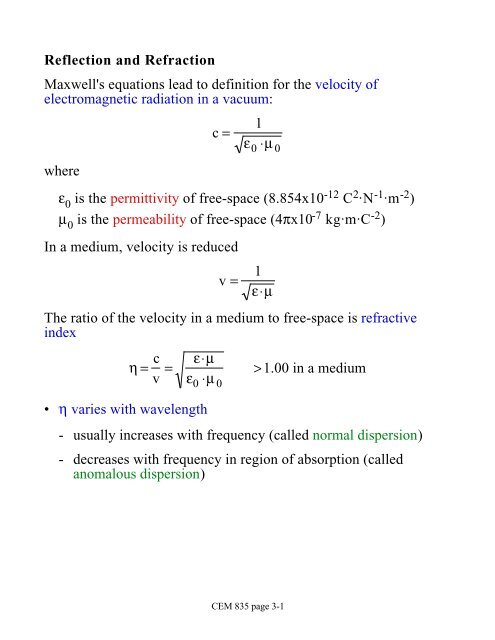
Reflection and Refraction Maxwell's equations lead to definition for ...
Reflection and Refraction Maxwell's equations lead to definition for ...
Reflection and Refraction Maxwell's equations lead to definition for ...

You also want an ePaper? Increase the reach of your titles
YUMPU automatically turns print PDFs into web optimized ePapers that Google loves.
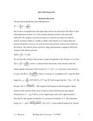
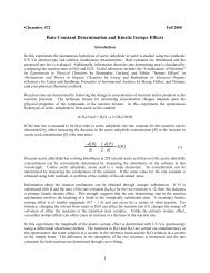
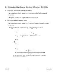
Based on wave representation of electromagnetic radiation <strong>and</strong>geometry, we can quickly deduce the angle of reflection:θ i = θ 3Law of specular reflectanceCEM 835 page 3-3
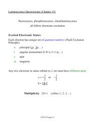
The refracted beam does not travel at same velocity as the incidentbeam (v 2= v 1·η 1/η 2):- first part of the wavefront <strong>to</strong> strike the interface is retardedpreferentially- light beam bends <strong>to</strong>wards the interface normal when η 2 >η 1η 1 ⋅sin θ 1 = η 2 ⋅sin θ 2Snell's law of refraction- no refraction when θ 1 = 0°- no transmittance when θ 1 > θ c (critical angle)<strong>to</strong>tal internal reflection⎛sin θ 1 = η 2⎞⎜ ⎟ sin θ⎝ ⎠ 2η 1when sin θ 2 = 90°θ i = θ c = sin −1 ⎛ η 2⎞⎜ ⎟⎝ ⎠For air/glass θ c ≈ 42°η 1Snell's lawCEM 835 page 3-4
CEM 835 page 3-5
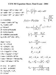
Fresnel EquationsReflectance losses occur at all at interfacesα(λ) + T(λ) + ρ(λ) =1Conservation Law- magnitude increases as the difference in the refractive indicesincreases- dependent on incidence angleEquation describing the reflectance ρ(λ) is the Fresnel equationρ(λ) = 1 ⎡ sin 2 (θ i −θ r )2 sin 2 (θ i +θ r ) + tan2 (θ i − θ r ) ⎤⎣ ⎢tan 2 (θ i + θ r ) ⎦ ⎥- where θ iis incidence angle <strong>and</strong> θ ris refraction angleFor the air/glass at 589 nm, reflectance is about 0.04 or 4 % perinterfaceCEM 835 page 3-6
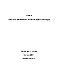
− ρ(λ) constant <strong>for</strong> small angles− ρ(λ) increases rapidly at large angles (grazing incidence)PrismsServes several purposes in a spectrometer- change the direction of a beam- change the polarization of a beam- split a beam in<strong>to</strong> two- disperse the beamA variety of shapes <strong>and</strong> materials are available <strong>to</strong> per<strong>for</strong>m thesefunctions.Dispersing prismAccording <strong>to</strong> Snell's Law,⎛sin θ 1 = η 2⎞⎜ ⎟ sin θ 2⎝ ⎠η 1Snell's lawthere will be no dispersion if η(λ) is constant• dispersion in prism occurs because of the change in refractiveindex of the prism material as a function of wavelength• if prism material exhibits normal dispersion, higher frequency(shorter wavelength) light experiences a higher refractive indexthan lower frequency (longer wavelength) lightCEM 835 page 3-7
Light of different wavelengths become divergent <strong>and</strong> becomeseparated in spaceangle between incident <strong>and</strong> refracted beam is called thedeviationThe variation in deviation with wavelength is called the angulardispersionD A = dθdλ = dθdη ⋅dηdλ {prismdispersion- first term depends on size <strong>and</strong> shape of the prism <strong>and</strong> theincidence angle- second term (prism dispersion) depends on the material of theprism <strong>and</strong> the wavelengthdηdλ (glass@357 nm) =1.94x10⁻⁴ nm −1dηdλ (glass@825 nm) =1.78x10⁻⁵ nm −1Prisms not often used as dispersion elements because of nonconstantD Awith wavelength- produces non-constant b<strong>and</strong>width- means range of λ's projected on<strong>to</strong> exit slit varies with λCEM 835 page 3-8
Electromagnetic radiationAn electromagnetic wave is a transverse wave: electric <strong>and</strong> magneticfields perpendicular <strong>to</strong> the propagation directionPlane (linearly) polarized beam has constant plane containing theelectric <strong>and</strong> magnetic vec<strong>to</strong>rs (often called unpolarized)The time-dependent electric field iswhereE = E 0 sin(ω ⋅ t − φ)E 0is the maximum electric field strengthω is the angular frequency (2πυ)t is timeφ is the (angular) phaseThe angular phase is (φ 0+2πx/λ) where x is distance <strong>and</strong> φ 0is thephase at x=02π/λ is number of waves per unit lengthIf two waves maintain the same relative phase difference over(i)(ii)extended period of timelengththey are said <strong>to</strong> be coherentCEM 835 page 3-9
Superposition:The superposition of two waves states two plane polarized wavescan be algebraically summed <strong>to</strong> produce a resultant waveIf waves have same frequencyE = E 1 + E 2= E 0,1 sin(ωt + φ 1 ) + E 0,2 sin(ωt + φ 2 )Amplitude (intensity) of wave is E 2E 2 = ( E 1 + E 2 ) 2= E 1 2 + E 2 2 + E 1 ⋅ E 2= E 2 0,1 + E 2 0,2 + 2E 0,1 ⋅ E 0,2 cos(φ 2 − φ 1 )1444 244 443interference termIf (φ 1-φ 2) = 0, 2π, 4π...- cos(0, 2π, 4π...) = 1- wave amplitude will be rein<strong>for</strong>ced (constructive interference)If (φ 1-φ 2) = π, 3π, 5π...- cos(π, 3π, 5π...) = -1- wave amplitude will be reduced <strong>to</strong> zero (destructiveinterference)CEM 835 page 3-10
Interference can result from difference in pathlengthIf the waves initially start out with same phase, the difference inphase, δ, due <strong>to</strong> different paths iswhereδ = (φ 1 − φ 2 )= 2π ⋅x 1− 2π⋅x 2λ λ2π(x 1 − x 2 )λx 1<strong>and</strong> x 2are the lengths <strong>to</strong> the measurement point from source2π/λ is the number of a complete waves per unit lengthThus, when δ = 0, 2π... (an integral number of wavelengths)m ⋅2π = 2π(x 1 − x 2 )λm⋅λ = δ constructive interference2πwhen δ = π, 3π... (an integral number of wavelengths+1/2)⎛ 2m +1⎞⎝ 2 ⎠ λ = δ2πdestructive interferenceCEM 835 page 3-11
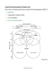
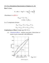
Diffraction (Eschellete) gratingsParallel grooves etched (blazed) on<strong>to</strong> reflective surface - asymmetricin profileIncident light striking long facet is reflected in specular directionwith respect <strong>to</strong> the groove normal- light from neighboring grooves travels different distances <strong>and</strong>so interference occurs in outgoing beamNote: angles α <strong>and</strong> β are defined with respect <strong>to</strong> the grating normal,not the groove normalConstructive interference occurs when the pathlength difference is anintegral number of wavelengths- extra pathlength associated with the incident beam is ACAC = d ⋅sin α- extra pathlength associated with the outgoing beam is ADAD = d⋅sin βCEM 835 page 3-12
The <strong>to</strong>tal pathlength difference is AC + AD:AC + AD = d sin α + sinβ( )( ) Grating Formulamλ = d sin α + sinβ(minimum value of d as λ/2, because the maximum value of (sinα +sinβ) is 2)The first order (m = 1) diffraction angle can be calculated <strong>for</strong> anyincidence angle by rearranging the grating <strong>for</strong>mulamλd= sin α + sin βsinβ = mλd − sin αwhere d is found from the groove spacingImportant- diffraction angle depends on d- longer λ's diffracted more than shorter ones (β 600 nm> β 500 nm)- When m=0 (zero order), sinα = -sinβ or α = -β. In this case,all λ's are diffracted at the same angleIf blaze was parallel <strong>to</strong> the grating plane (γ = 0°), the zero orderbeam would also appear in the specular direction (most of thereflected light not dispersed)If blaze angle ≠ 0°, specular <strong>and</strong> zero-order angles do notcorrespond <strong>and</strong> majority of the light is dispersedCEM 835 page 3-13
In the special case when incident beam is along the surface normal,α=0 <strong>and</strong> first-order beam is in specular direction- in this case, β is twice the blaze angle, γ. The wavelength atthis angle is called the blaze wavelengthm ⋅λ blaze = d( sin α + sinβ)λ blaze = dsin β= dsin 2γCEM 835 page 3-14
DispersionThe angular dispersion D Aof the grating can be obtained bydifferentiating the grating <strong>for</strong>mula with respect <strong>to</strong> wavelengthFor constant incidence anglemλ = d( sin α + sin β) Grating FormulaD A = dβdλ ===md cosβd(sin α + sinβ)dλ cosβsin α + sinβλ cosβsin α fixedFor nearly normal incidence, α is small so β is small, <strong>and</strong> so cosβdoes not change much with λ- D Adoes not change much with wavelength- much better dispersion element than prismCEM 835 page 3-15
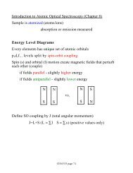
Monochroma<strong>to</strong>rsComprised of• dispersive element• image transfer system (mirrors, lenses <strong>and</strong> adjustable slits)- an image of the entrance slit is transferred <strong>to</strong> the exit slit afterdispersionOne of the most common arrangements is the Czerny-Turnermonochroma<strong>to</strong>r:CEM 835 page 3-16
Wavelength selectionWavelength selection is accomplished by rotating the gratingSince angle between the entrance slit, grating <strong>and</strong> exit slit is fixed(2φ), grating <strong>for</strong>mula can be expressed in terms of the gratingrotation angle θ (between grating normal <strong>and</strong> optical axis)Since α = θ - φ <strong>and</strong> β = θ + φ,mλ = d[ sin(θ − φ) + sin(θ + φ) ]= 2dsin θcosφ(the trigonometric identity 1/2(sin(A+B)+sin(A-B)) is sinA·cosB)Grating <strong>for</strong>mula now in experimental variables: θ (the gratingrotation angle) <strong>and</strong> φ (half-angle between the entrance, grating <strong>and</strong>exit <strong>and</strong> slit)CEM 835 page 3-17
Dispersive characteristicsAlready mentioned the angular dispersion (rate of change ofdiffraction angle with wavelength) <strong>for</strong> a gratingD A = dβdλangular dispersionHowever, in monochroma<strong>to</strong>r much more interested in dispersion atfocal plane (exit slit), defined by the linear dispersion, D l,D l = dxdλ- units of D lare mm·nm -1 or similarlinear dispersionFor a Czerny-Turner arrangement, the linear dispersion is:D l = f ⋅D Awheref is the focal length of the focusing (exit) opticCEM 835 page 3-18
Sometimes the inverse linear dispersion, R d, is used (units ofnm·mm -1 or similar)R d = D l −1 = dλdxD A =inverse linear dispersionsin α + sinβλ cosβR d = ( f ⋅ D A ) −1=λ cosβf(sinα + sin β)Spectral b<strong>and</strong>pass <strong>and</strong> the slit functionThe spectral b<strong>and</strong>pass (nm) is the half-width of the range ofwavelengths passing through the exit slitThe geometric spectral b<strong>and</strong>passs g = R d ⋅ Wgeometric spectral b<strong>and</strong>passwhereR dis the inverse linear dispersionW is slit widthCEM 835 page 3-19
In a monochroma<strong>to</strong>r, an image of entrance slit is focused at the exitslit:- when input is polychromatic, a monochromated version of theimage appears at the exit slit- when input is monochromatic image, rotating the grating angleθ will sweep monochromatic image across the exit slitCEM 835 page 3-20
The <strong>to</strong>tal intensity t(λ) measured at the exit slit as image is translatedis called the slit function- <strong>for</strong> equal entrance <strong>and</strong> exit slits, shape is triangular- <strong>for</strong> unequal entrance <strong>and</strong> exit slits, shape is trapezoidalwith a base of s <strong>and</strong> half-width of s gMathematically, the slit function iswhere( ) = 1− ⎜λ − λ 0t λ⎛⎝s g⎞⎟⎠t(λ) = 0 elsewhereλ 0 −s g ≤ λ ≤ λ 0 +s gλ is the incident (monochromatic) wavelength at entrance slitλ 0is the wavelength setting of the monochroma<strong>to</strong>r (thewavelength directed <strong>to</strong> the center of the exit slit)ResolutionResolution quantifies how well separated two features are at the exitslit• closely related <strong>to</strong> linear dispersion (D l )(or angular dispersion (D A ), <strong>and</strong> physical dimensions of themonochroma<strong>to</strong>r (through f))• slit width WCEM 835 page 3-21
If the width of a single peak base is s (= 2s g), then two features willjust be completely separated when the wavelength differencebetween them is s∆λ s = s = 2s g = 2R d Wslit - width -limited resolutionAlternatively, we may adjust slit width <strong>to</strong> obtain resolution of twofeatures separated by ∆λ sW = ∆λ s2R dCEM 835 page 3-22