

Masterpact UR 50 - engineering site - Schneider Electric
Masterpact UR 50 - engineering site - Schneider Electric
Masterpact UR 50 - engineering site - Schneider Electric

You also want an ePaper? Increase the reach of your titles
YUMPU automatically turns print PDFs into web optimized ePapers that Google loves.
PresentationPrinciple of operation 0<strong>Masterpact</strong> <strong>UR</strong>, installed in a circuit, permanently senses the current of theinstallation. This sensing is done by air CTs (Rogowsky type) integrated in the<strong>Masterpact</strong> <strong>UR</strong>.On operation<strong>Masterpact</strong> <strong>UR</strong> opening and closing sequence is achieved by the standard energymechanism. The breaker can be locally or remotely opened and closed.On overload or low short-circuitIn case of an overload or a low short-circuit, the Ir or Isd thresholds of the Micrologiccontrol unit are activated and the trip order is given via the Mitop coil (MITOP) to theopening mechanism. The total breaking time is approximatively 80 ms.DB109571Diagram Opening mechanism.DB110798On high short-circuitb in case of a high short-circuit, the “<strong>UR</strong> control” module directly linked to the aircurrent transformer, analyses the slope (di/dt) and its amplitude in a very short time(< 240 ms)b in case of overtaking the two thresholds, the “<strong>UR</strong> control” gives a simultaneousorder to the thyristors and the MITOP:v the thyristors release the capacitor electrostatic energy in the Thomson Effect Coilsprovoking the immediate repulsion of the contacts (< 1 ms). The total breaking timeis lower than 8 msv the MITOP confirms the opening.DB110815Diagram Opening mechanism - “<strong>UR</strong> power”- Thomson effect thruster.
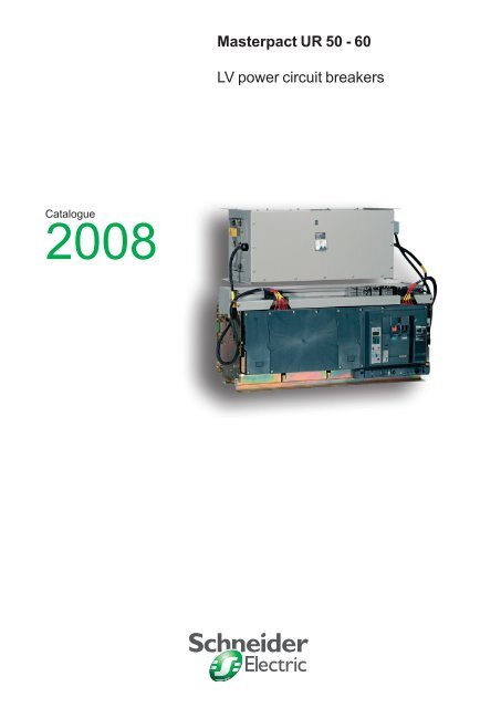
Description<strong>Masterpact</strong> <strong>UR</strong><strong>Masterpact</strong> <strong>UR</strong> <strong>50</strong>-60 3 poles withdrawable versionPB101593<strong>Masterpact</strong> <strong>UR</strong> <strong>50</strong>-60 front view.PB101606-64<strong>Masterpact</strong> <strong>UR</strong> <strong>50</strong>-60 rear view.DB114803
Description <strong>Masterpact</strong> <strong>UR</strong>ChassisDB114806DB11080010
Description<strong>Masterpact</strong> <strong>UR</strong>Circuit breakerDB114804DB110802FrontDB11480711
Description“<strong>UR</strong> power” module and“<strong>UR</strong> control” module“<strong>UR</strong> power” <strong>50</strong>-60DB114805“<strong>UR</strong> control” moduleDB114810DB114808DB11480912
<strong>Masterpact</strong> <strong>UR</strong>Functions and characteristicsPresentation 3<strong>UR</strong><strong>50</strong> - <strong>UR</strong>60 circuit breakers A-2Drawout 3-pole devices A-2Protection system A-3Micrologic control units A-4Micrologic A “ammeter” A-4Micrologic P “power” A-6Micrologic H “harmonics” A-10Accessories and test instruments A-12Protection by Thomson effect A-13“<strong>UR</strong> control” module A-13Accessories and test instruments A-15Operation A-17<strong>Electric</strong>al closing A-17Opening A-19Auxiliaries A-20Remote tripping by MN or MX A-21Remote ON/OFF A-22“<strong>UR</strong> power” and “<strong>UR</strong> control” A-23Customer options A-23Communication A-25COM Modbus option in <strong>Masterpact</strong> <strong>UR</strong> A-25Overview of functions A-26“<strong>UR</strong> control” and “<strong>UR</strong> power” modules A-27<strong>Masterpact</strong> <strong>UR</strong> in a communication network A-28Connections A-29Optional accessories A-29Locking A-30On the device A-30On the chassis A-31Indication contacts A-32Accessories A-34Installation recommendations B-1Dimensions and connections C-1<strong>Electric</strong>al diagrams D-1Additional characteristics E-1Catalogue numbers F-1A-1
Functionsand characteristics<strong>UR</strong><strong>50</strong> - <strong>UR</strong>60 circuit breakersDrawout 3-pole devicesPB101595-64Common characteristicsNumber of poles 3Rated insulation voltage (V) Ui 1000Impulse withstand voltage (kV) Breaker (cat. IV) Uimp 12“<strong>UR</strong> power” (cat. III) Uimp 4Auxiliary circuits (cat. III) Uimp 8Rated operational voltage (V AC <strong>50</strong>/60 Hz) Ue 690Suitability for isolation IEC 60947-2Degree of pollution IEC 60664-1 3Sensor selectionRating (A) <strong>50</strong>00 6000Ir thresold setting (A) 2000 to <strong>50</strong>00 2400 to 6000Circuit-breaker characteristics as per IEC 60947-2 <strong>UR</strong><strong>50</strong> <strong>UR</strong>60Rated current (A) at 45 °C <strong>50</strong>00 6000Type of circuit breaker L LUltimate breaking capacity (kA rms)V AC <strong>50</strong>/60 HzIcu220/415/440 V690 VRated service breaking capacity (kA rms) Ics % Icu 100 % 100 %Utilisation category A ARated short-time withstand current 1 s 690 V 20 20(kA rms) [ 0% + 20%] AC <strong>50</strong>/60 HzIntegrated instantaneous protection [kA peak ±10 %][kA rms]Rated making capacity (kA peak)V AC <strong>50</strong>/60 HzBreak time (ms) between fault detectionand arc extinction (standard protection)Break time (ms) between fault detectionand arc extinction (Thomson thruster)Icm220/415/440 V690 V1<strong>50</strong>10046323302201<strong>50</strong>100463233022080 80< 8 < 8Closing time (ms) < 80 < 80Mechanical and electrical durability as per IEC 60947-2 at In <strong>UR</strong><strong>50</strong> <strong>UR</strong>60C/O cycles Mechanical Without maintenance 2<strong>50</strong>0 2<strong>50</strong>0Rated current In (A) <strong>50</strong>00 6000C/O cycles <strong>Electric</strong>al Without maintenance 440 V <strong>50</strong>0 <strong>50</strong>0690 V <strong>50</strong>0 <strong>50</strong>0Maximum number of trips by Thomson effect (without current) 100 100A-2
Functionsand characteristicsProtection systemPB101594-63<strong>Masterpact</strong> <strong>UR</strong> is equipped with two control units:b one Micrologic control unit (Fig. 1) for protection against overloads, low shortcircuitsand insulation faultsb a specific control unit “<strong>UR</strong> control” module for protection against high short-circuits(Fig. 2).This module is associated to the “<strong>UR</strong> power” module for the tripping by Thomsoneffect.DB110809DB110810Fig. 2.Fig. 1.A-3
Functionsand characteristicsMicrologic control unitsMicrologic A “ammeter”DB101125Micrologic A control units protect powercircuits.They also offer measurements, display,communication and current maximeters.Version 6 provides earth-fault protection,Micrologic A complies to IACSrecommendation and trust be used whenMarine certification is requested.Protection settings...................................................................Protection thresholds and delays are set using the adjustment dials.The selected values are momentarily displayed in amperes and in seconds.Overload protectionTrue rms long-time protection.Thermal memory: thermal image before and after tripping.Setting accuracy may be enhanced by limiting the setting range using a differentlong-time rating plug.The long-time rating plug “OFF” enables to cancel the overload protection.Short-circuit protectionShort-time (rms) and instantaneous protection.Selection of I 2 t type (ON or OFF) for short-time delay.Earth fault protectionResidual or source ground return.Selection of I 2 t type (ON or OFF) for delay.“Ammeter” measurements......................................................Micrologic A control units measure the true rms value of currents.They provide continuous current measurements from 0.2 to 20 In and are accurateto within 1.5 % (including the sensors).A digital LCD screen continuously displays the most heavily loaded phase (Imax) ordisplays the I 1, I 2, I 3, I N, I g, I Dn, stored-current (maximeter) and setting values bysuccessively pressing the navigation button.The optional external power supply makes it possible to display currents < 20 % In.Below 0.05 In, measurements are not significant. Between 0.05 and 0.2 In, accuracyis to within 0.5 % In + 1.5 % of the reading.Communication optionIn conjunction with the COM communication option, the control unit transmits thefollowing:b setting valuesb all “ammeter” measurementsb tripping causesb maximeter reset.1 Long-time current setting and tripping delay.2 Overload signal (LED) at 1.125 Ir.3 Short-time pick-up and tripping delay.4 Instantaneous pick-up.5 Earth-fault pick-up and tripping delay.6 Earth-fault test button.7 Long-time rating plug screw.8 Test connector.9 Lamp test, reset and battery test.10 Indication of tripping cause.11 Digital display.12 Three-phase bargraph and ammeter.13 Navigation buttons.Note: Micrologic A control units come with a transparent leadsealcover as standard.A-4
Functionsand characteristicsMicrologic control unitsMicrologic A “ammeter”ProtectionMicrologic 2.0 ALong timeCurrent setting (A) Ir = In x … 0.4 0.5 0.6 0.7 0.8 0.9 0.95 0.98 1Tripping between 1.05 and 1.20 x IrOther ranges or disable by changing long-time rating plugTime setting tr (s) 0.5 1 2 4 8 12 16 20 24Time delay (s) Accuracy: 0 to -30 % 1.5 x Ir 12.5 25 <strong>50</strong> 100 200 300 400 <strong>50</strong>0 600Accuracy: 0 to -20 % 6 x Ir 0.7 (1) 1 2 4 8 12 16 20 24Accuracy: 0 to -20 % 7.2 x Ir 0.7 (2) 0.69 1.38 2.7 5.5 8.3 11 13.8 16.6Thermal memory20 minutes before and after tripping(1) 0 to -40 % - (2) 0 to -60 %InstantaneousPick-up (A) Isd = Ir x … 1.5 2 2.5 3 4 5 6 8 10Accuracy: ±10 %Time delayMax resettable time: 20 msMax break time: 80 msDB114811AmmeterMicrologic 2.0 AContinuous current measurementsDisplay from 20 to 200 % of In I1 I2 I3 INAccuracy: 1.5 % (including sensors)No auxiliary source (where I > 20 % In)MaximetersI1 max I2 max I3 max IN maxProtectionMicrologic 5.0 / 6.0 ALong timeMicrologic 5.0 / 6.0 ACurrent setting (A) Ir = In x … 0.4 0.5 0.6 0.7 0.8 0.9 0.95 0.98 1Tripping between 1.05 and 1.20 x IrOther ranges or disable by changing long-time rating plugTime setting tr (s) 0.5 1 2 4 8 12 16 20 24Time delay (s) Accuracy: 0 to -30 % 1.5 x Ir 12.5 25 <strong>50</strong> 100 200 300 400 <strong>50</strong>0 600Accuracy: 0 to -20 % 6 x Ir 0.7 (1) 1 2 4 8 12 16 20 24Accuracy: 0 to -20 % 7.2 x Ir 0.7 (2) 0.69 1.38 2.7 5.5 8.3 11 13.8 16.6Thermal memory20 minutes before and after tripping(1) 0 to -40 % - (2) 0 to -60 %Short timePick-up (A) Isd = Ir x … 1.5 2 2.5 3 4 5 6 8 10Accuracy: ±10 %Time setting tsd (s) Settings I 2 t Off 0 0.1 0.2 0.3 0.4I 2 t On - 0.1 0.2 0.3 0.4Time delay (ms) at 10 x Ir tsd (max resettable time) 20 80 140 230 3<strong>50</strong>(I 2 t Off or I 2 t On) tsd (max break time) 80 140 200 320 <strong>50</strong>0InstantaneousPick-up (A) Ii = In x … 2 3 4 6 8 10 12 15 offAccuracy: ±10 %Time delayMax resettable time: 20 msMax break time: 80 msEarth faultMicrologic 6.0 APick-up (A) Ig = In x … A B C D E F G H JAccuracy: ±10 % In y 400 A 0.3 0.3 0.4 0.5 0.6 0.7 0.8 0.9 1400 A < In < 12<strong>50</strong> A 0.2 0.3 0.4 0.5 0.6 0.7 0.8 0.9 1In u 12<strong>50</strong> A <strong>50</strong>0 640 720 800 880 960 1040 1120 1200Time setting tg (s) Settings I 2 t Off 0 0.1 0.2 0.3 0.4I 2 t On - 0.1 0.2 0.3 0.4Time delay (ms) tg (max resettable time) 20 80 140 230 3<strong>50</strong>at In or 1200 A (I 2 t Off or I 2 t On) tg (max break time) 80 140 200 320 <strong>50</strong>0AmmeterMicrologic 5.0 / 6.0 AContinuous current measurementsDisplay from 20 to 200 % of In I1 I2 I3 IN Ig IDnAccuracy: 1.5 % (including sensors)No auxiliary source (where I > 20 % In)MaximetersI1 max I2 max I3 max IN max Ig max IDn maxNote : Micrologic needs an external 24 V DC voltage supply to operate.This voltage is supplied by the “<strong>UR</strong> power” module when energized.The test / reset button resets maximeters, clears the tripping indication and tests the battery.DB114812DB114813A-5
Functionsand characteristicsMicrologic control unitsMicrologic P “power”Micrologic P control units include all thefunctions offered by Micrologic A.In addition, they measure voltages andcalculate power and energy values.They also offer new protection functionsbased on currents, voltages, frequency andpower reinforce load protection.Protection settings......................................................... +The adjustable protection functions are identical to those of Micrologic A (overloads,short-circuits, earth-fault and earth-leakage protection).Fine adjustmentWithin the range determined by the adjustment dial, fine adjustment of thresholds (towithin one ampere) and time delays (to within one second) is possible on the keypador remotely using the COM option.IDMTL (Inverse Definite Minimum Time lag) settingCoordination with fuse-type or medium-voltage protection systems is optimised byadjusting the slope of the overload-protection curve. This setting also ensures betteroperation of this protection function with certain loads.DB101485Programmable alarms and other protection..........................Depending on the thresholds and time delays set using the keypad or remotely usingthe COM option, the Micrologic P control unit monitors currents and voltage, power,frequency and the phase sequence. Each threshold overrun is signalled remotely viathe COM option. Each threshold overrun may be combined with tripping (protection)or an indication carried out by an optional M2C or M6C programmable contact(alarm), or both (protection and alarm).Load shedding and reconnection...........................................Load shedding and reconnection parameters may be set according to the power orthe current flowing through the circuit breaker. Load shedding is carried out by asupervisor via the COM option or by an M2C or M6C programmable contact.Measurements..........................................................................The Micrologic P control unit calculates in real time all the electrical values (V, A, W,VAR, VA, Wh, VARh, VAh, Hz), power factors and crest factors.The Micrologic P control unit also calculates demand current and demand powerover an adjustable time period. Each measurement is associated with a minimeterand a maximeter.In the event of tripping on a fault, the interrupted current is stored. The optionalexternal power supply makes it possible to display the value with the circuit breakeropen or not supplied.Histories and maintenance indicators....................................The last ten trips and alarms are recorded in two separate history files. Maintenanceindications (contact wear, operation cycles, etc.) are recorded for local access.Indication option via programmable contactsThe M2C (two contacts) and M6C (six contacts) auxiliary contacts may be used tosignal threshold overruns or status changes. They can be programmed using thekeypad on the Micrologic P control unit or remotely using the COM option.1 Long-time current setting and tripping delay.2 Overload signal (LED).3 Short-time pick-up and tripping delay.4 Instantaneous pick-up.5 Earth-fault pick-up and tripping delay.6 Earth-fault test button.7 Long-time rating plug screw.8 Test connector.9 Lamp + battery test and indications reset.10 Indication of tripping cause.11 High-resolution screen.12 Measurement display.13 Maintenance indicators.14 Protection settings.15 Navigation buttons.16 Hole for settings lockout pin on cover.Communication option (COM)The communication option may be used to:b remotely read and set parameters for the protection functionsb transmit all the calculated indicators and measurementsb signal the causes of tripping and alarmsb consult the history files and the maintenance-indicator register.b maximeter reset.An event log and a maintenance register, stored in control-unit memory but notavailable locally, may be accessed in addition via the COM option.Note: Micrologic P control units come with a non-transparentlead-seal cover as standard.A-6
Functionsand characteristicsMicrologic control unitsMicrologic P “power”Protection Micrologic 5.0 / 6.0 PLong time (rms)Micrologic 5.0 / 6.0 PCurrent setting (A) Ir = In x … 0.4 0.5 0.6 0.7 0.8 0.9 0.95 0.98 1Tripping between 1.05 and 1.20 x IrOther ranges or disable by changing long-time rating plugTime setting tr (s) 0.5 1 2 4 8 12 16 20 24Time delay (s) Accuracy: 0 to -30 % 1.5 x Ir 12.5 25 <strong>50</strong> 100 200 300 400 <strong>50</strong>0 600Accuracy: 0 to -20 % 6 x Ir 0.7 (1) 1 2 4 8 12 16 20 24Accuracy: 0 to -20 % 7.2 x Ir 0.7 (2) 0.69 1.38 2.7 5.5 8.3 11 13.8 16.6IDMTL setting Curve slope SIT VIT EIT HVFuseDTThermal memory20 minutes before and after tripping(1) 0 to -40 % - (2) 0 to -60 %Short time (rms)Pick-up (A) Isd = Ir x … 1.5 2 2.5 3 4 5 6 8 10Accuracy: ±10 %Time setting tsd (s) Settings I 2 t Off 0 0.1 0.2 0.3 0.4I 2 t On - 0.1 0.2 0.3 0.4Time delay (ms) at 10 Ir tsd (max resettable time) 20 80 140 230 3<strong>50</strong>(I 2 t Off or I 2 t On) tsd (max break time) 80 140 200 320 <strong>50</strong>0InstantaneousPick-up (A) Ii = In x … 2 3 4 6 8 10 12 15 offAccuracy: ±10 %Time delayMax resettable time: 20 msMax break time: 80 msEarth faultMicrologic 6.0 PPick-up (A) Ig = In x … A B C D E F G H JAccuracy: ±10 % In y 400 A 0.3 0.3 0.4 0.5 0.6 0.7 0.8 0.9 1400 A < In < 12<strong>50</strong> A 0.2 0.3 0.4 0.5 0.6 0.7 0.8 0.9 1In u 12<strong>50</strong> A <strong>50</strong>0 640 720 800 880 960 1040 1120 1200Time setting tg (s) Settings I 2 t Off 0 0.1 0.2 0.3 0.4I 2 t On - 0.1 0.2 0.3 0.4Time delay (ms) tg (max resettable time) 20 80 140 230 3<strong>50</strong>at In or 1200 A (I 2 t Off or I 2 t On) tg (max break time) 80 140 200 320 <strong>50</strong>0Alarms and other protectionMicrologic 5.0 / 6.0 PCurrent Threshold DelayCurrent unbalance Iunbalance 0.05 to 0.6 Iaverage 1 to 40 sMaximum average current Imax demand : I1, I2, I3, IN, 0.2 In to In 15 to 1<strong>50</strong>0 sEarth fault alarmIt 20 A to 1200 A 1 to 10 sVoltageVoltage unbalance Uunbalance 2 to 30 % x Uaverage 1 to 40 sMinimum voltage Umin 100 to Umax between phases 1.2 to 5 sMaximum voltage Umax Umin to 1200 between phases 1.2 to 5 sPowerReverse power rP 5 to <strong>50</strong>0 kW 0.2 to 20 sFrequencyMinimum frequency Fmin 45 to Fmax 1.2 to 5 sMaximum frequency Fmax Fmin to 440 Hz 1.2 to 5 sPhase sequenceSequense (alarm) DØ Ø1/2/3 or Ø1/3/2 0.3 sLoad shedding and reconnectionMicrologic 5.0 / 6.0 PMeasured value Threshold DelayCurrent I 0.5 to 1 Ir per phase 20 % tr to 80 % trPower P 200 kW to 10 MW 10 to 3600 sDB114816DB114815DB114813DB114814+Note: Micrologic needs an external 24 V DC voltage supply to operate.This voltage is supplied by the “<strong>UR</strong> power” module when energized.The test / reset button resets maximeters, clears the tripping indication and tests the battery.A-7
Functionsand characteristicsMicrologic control unitsMicrologic P “power”DB101133DB101134Navigation from one display to another is intuitive. The six buttons on the keypadprovide access to the menus and easy selection of values. When the setting cover isclosed, the keypad may no longer be used to access the protection settings, but stillprovides access to the displays for measurements, histories, indicators, etc.DB101135Default display.Display of a voltage.DB101136Display of a maximum current..Display of a power.Measurements..........................................................................Instantaneous valuesThe value displayed on the screen is refreshed every second.Minimum and maximum values of measurements are stored in memory (minimetersand maximeters).CurrentsI rms A 1 2 3 NA E-fault E-leakageI max rms A 1 2 3 NA E-fault E-leakageVoltagesU rms V 12 23 31V rms V 1N 2N 3NU average rms V (U12 + U23 + U31) / 3U unbalance %Power, energyP active, Q reactive, S apparent W, Var, VA TotalsE active, E reactive, E apparent Wh, VARh, VAh Totals consumed - suppliedTotals consumedTotals suppliedPower factor PF TotalFrequenciesFHzDB101137Display of a frequency.DB101138Display of a demand power.Demand meteringThe demand is calculated over a fixed or sliding time window that may beprogrammed from 5 to 60 minutes. According to the contract signed with the powersupplier, an indicator associated with a load shedding function makes it possible toavoid or minimise the costs of overrunning the subscribed power. Maximum demandvalues are systematically stored and time stamped (maximeter).CurrentsI demand A 1 2 3 NA E-fault E-leakageI max demand A 1 2 3 NA E-fault E-leakagePowerP, Q, S demand W, Var, VA TotalsP, Q, S max demand W, Var, VA TotalsMinimeters and maximetersOnly the current and power maximeters may be displayed on the screen.DB101139Display of a tripping history.DB101140Display after tripping.Histories....................................................................................The last ten trips and alarms are recorded in two separate history files that may bedisplayed on the screen:bvvvbvvvtripping history:type of faultdate and timevalues measured at the time of tripping (interrupted current, etc.)alarm history:type of alarmdate and timevalues measured at the time of the alarm.Maintenance indicators (with COM option)............................A number of maintenance indicators may be called up on the screen:b operation counter:v cumulative totalv total since last reset.A-8
Functionsand characteristicsMicrologic control unitsMicrologic P “power”DB101523Display of an event log on a supervisor.With the communication optionAdditional measurements, maximeters and minimetersCertain measured or calculated values are only accessible with the COMcommunication option:bbI peak / 2, (I1 + I2 + I3)/3, I unbalanceload level in % Irtotal power factor.bThe maximeters and minimeters are available only via the COM option for use witha supervisor.Event logAll events are time stamped:b tripsb beginning and end of alarmsb modifications to settings and parametersb counter resetsb system faults:v fallback positionv thermal self-protectionb loss of timeb overrun of wear indicatorsb test-kit connections etc.Maintenance registerUsed as an aid in troubleshooting and to better plan for device maintenanceoperations:bbbbhighest current measuredoperation counternumber of test-kit connectionsnumber of trips in operating mode and in test mode.Additional technical characteristicsSetting the display languageSystem messages may be displayed in six different languages. The desiredlanguage is selected via the keypad.Protection functionsAll current-based protection functions require no auxiliary source. Voltage-basedprotection functions are connected to AC power via a voltage measurement inputbuilt into the circuit breaker.Measurement functionsMeasurement functions are independent of the protection functions.b the high-accuracy measurement module operates independently of the protectionmodule, while remaining synchronised with protection events.Measurement-calculation modeb measurement functions implement the new “zero blind time” concept whichconsists in continuously measuring signals at a high sampling rate. The traditional“blind window” used to process samples no longer exists. This method ensuresaccurate energy calculations even for highly variable loads (welding machines,robots, etc.)b energies are calculated on the basis of the instantaneous power values, in twomanners:v the traditional mode where only positive (consumed) energies are consideredv the signed mode where the positive (consumed) and negative (supplied) energiesare considered separately.Accuracy of measurements (including sensors):b voltage (V) 0.5 %b current (A) 1.5 %b frequency (Hz) 0.1 %b power (W) and energy (Wh) 2 %.Stored informationThe fine setting adjustments, the last 100 events and the maintenance registerremain in the control-unit memory even when power is lost.Time-stampingTime-stamping is activated as soon as time is set manually or by a supervisor.No external power supply module is required (max. drift of 1 hour per year).ResetAn individual reset, via the keypad or remotely, acts on alarms, minimum andmaximum data, peak values, the counters, the indicators.A-9
Functionsand characteristicsMicrologic control unitsMicrologic H “harmonics”DB116358Micrologic H control units include all thefunctions offered by Micrologic P.Integrating significantly enhancedcalculation and memory functions, theMicrologic H control unit offers in-depthanalysis of power quality and detailed eventdiagnostics. It is intended for operation witha supervisor.In addition to the Micrologic P functions, the Micrologic H control unit offers:b in-depth analysis of power quality including calculation of harmonics and thefundamentalsb diagnostics aid and event analysis through waveform captureb enhanced alarm programming to analyse and track down a disturbance on the ACpower system.Measurements..........................................................................The Micrologic H control unit offers all the measurements carried out by Micrologic P,with in addition:bvvbvvvphase by phase measurements of:power, energypower factorscalculation of:current and voltage total harmonic distortion (THD)current, voltage and power fundamentalscurrent and voltage harmonics up to the 31st order.Instantaneous values displayed on the screenCurrentsI rms A 1 2 3 NA E-fault E-leakageI max rms A 1 2 3 NA E-fault E-leakageVoltagesU rms V 12 23 31V rms V 1N 2N 3NU average rms V (U12 + U23 + U31) / 3U unbalance %Power, energyP active, Q reactive, S apparent W, Var, VA Totals 1 2 3E active, E reactive, E apparent Wh, VARh, VAh Totals consumed - suppliedTotals consumedTotals suppliedPower factor PF Total 1 2 3FrequenciesFHzPower-quality indicatorsTotal fundamentalsU I P Q STHD % U IU and I harmonics Amplitude 3 5 7 9 11 13Harmonics 3, 5, 7, 9, 11 and 13, monitored by electrical utilities, are displayed on the screen.Demand measurementsSimilar to the Micrologic P control unit, the demand values are calculated over a fixedor sliding time window that may be set from 5 to 60 minutes.CurrentsI demand A 1 2 3 NA E-fault E-leakageI max demand A 1 2 3 NA E-fault E-leakagePowerP, Q, S demand W, Var, VA TotalsP, Q, S max demand W, Var, VA TotalsMaximetersOnly the current maximeters may be displayed on the screen.Histories and maintenance indicatorsThese functions are identical to those of the Micrologic P.Note: Micrologic H control units come with a non-transparentlead-seal cover as standard.A-10
Functionsand characteristicsMicrologic control unitsMicrologic H “harmonics”DB101521DB101522Display of harmonics up to 21th order.With the communication optionAdditional measurements, maximeters and minimetersCertain measured or calculated values are only accessible with the COMcommunication option:bbbbbbbbbI peak / 2 (I 1+ I 2+ I 3)/3, I unbalanceload level in % Irpower factor (total and per phase)voltage and current THDK factors of currents and average K factorcrest factors of currents and voltagesall the fundamentals per phasefundamental current and voltage phase displacementdistortion power and distortion factor phase by phaseamplitude and displacement of current and voltage harmonics 3 to 31.bThe maximeters and minimeters are available only via the COM option for use witha supervisor.Waveform captureThe Micrologic H control unit stores the last 4 cycles of each instantaneous currentor voltage measurement. On request or automatically on programmed events, thecontrol unit stores the waveforms. The waveforms may be displayed in the form ofoscillograms by a supervisor via the COM option. Definition is 64 points per cycle.Pre-defined analogue alarms (1 to 53)Each alarm can be compared to user-set high and low thresholds. Overrun of athreshold generates an alarm. An alarm or combinations of alarms can be linked toprogrammable action such as selective recording of measurements in a log,waveform capture, etc.Event log and maintenance registersThe Micrologic H offers the same event log and maintenance register functions asthe Micrologic P. In addition, it produces a log of the minimums and maximums foreach “real-time” value.DB101523Waveform capture.Log.Additional technical characteristicsSetting the display languageSystem messages may be displayed in six different languages. The desiredlanguage is selected via the keypad.Protection functionsAll current-based protection functions require no auxiliary source. Voltage-basedprotection functions are connected to AC power via a voltage measurement inputbuilt into the circuit breaker.Measurement functionsMeasurement functions are independent of the protection functions.The high-accuracy measurement module operates independently of the protectionmodule, while remaining synchronised with protection events.Measurement-calculation modeAn analogue calculation function dedicated to measurements enhances theaccuracy of harmonic calculations and the power-quality indicators. The MicrologicH control unit calculates electrical magnitudes using 1.5 x In dynamics (20 x In forMicrologic P).Measurement functions implement the new “zero blind time” conceptEnergies are calculated on the basis of the instantaneous power values, in thetraditional and signed modes.Harmonic components are calculated using the discrete Fourier transform (DFT).Accuracy of measurements (including sensors):b voltage (V) 0.5 %b current (A) 1.5 %b frequency (Hz) 0.1 %b power (W) and energy (Wh) 2 %b total harmonic distortion 1 %.Stored informationThe fine-setting adjustments, the last 100 events and the maintenance registerremain in the control-unit memory even when power is lost.Time-stampingTime-stamping is activated as soon as time is set manually or by a supervisor. Noexternal power supply module is required (max. drift of 1 hour per year).ResetAn individual reset, via the keypad or remotely, acts on alarms, minimum andmaximum data, peak values, the counters, the indicators.A-11
Functionsand characteristicsMicrologic control unitsAccessories and test instrumentsPB100773-32Long-time rating plugFour interchangeable plugs may be used to limit the long-time threshold settingrange for higher accuracy.The time delay settings indicated on the plugs are for an overload of 6 Ir (for furtherdetails, see the characteristics on pages A-5 and A-7).As standard, control units are equipped with the 0.4 with to 1 plug.Setting rangesStandard Ir = In x… 0.4 0.5 0.6 0.7 0.8 0.9 0.95 0.98 1Low-setting option Ir = In x… 0.4 0.45 0.<strong>50</strong> 0.55 0.60 0.65 0.70 0.75 0.8High-setting option Ir = In x… 0.80 0.82 0.85 0.88 0.90 0.92 0.95 0.98 1Off plugNo long-time protection (Ir = In for Isd setting)Important: long-time rating plugs must always be removed before carrying out insulation ordielectric withstand tests.PB100774-32M2C.PB100781-32M6C.M2C, M6C programmable contactsThese contacts are optional equipment for the Micrologic P and H control units.They are described with the indication contacts for the circuit breakers.CharacteristicsM2C/M6CMinimum load10 mA/24 VBreaking capacity (A) V AC 240 5p.f.: 0.7380V DC 24 1.848 1.5125 0.42<strong>50</strong> 0.15M2C: 24 V DC power supplied by control unit (consumption 100 mA).M6C: external 24 V DC power supply required (consumption 100 mA).Spare partsPB100775-32Lead-seal cover.Lead-seal coversA lead-seal cover controls access to the adjustment dials.When the cover is closed:b it is impossible to modify settings using the keypad unless the settings lockout pinon the cover is removedb the test connector remains accessibleb the test button for the earth-fault and earth-leakage protection function remainsaccessible.Characteristicsb transparent cover for basic Micrologic and Micrologic A control unitsb non-transparent cover for Micrologic P and H control units.Spare batteryA battery supplies power to the LEDs identifying the tripping causes. Battery servicelife is approximately ten years.A test button on the front of the control unit is used to check the battery condition.The battery may be replaced on <strong>site</strong> when discharged.DB111579PB100837-68Portable test kit.Test equipmentsHand-held test kit (HHTK)The hand-held mini test kit may be used to:b check operation of the control unit and the tripping and pole-opening system bysending a signal simulating a short-circuitb supply power to the control units for settings via the keypad when thecircuit-breaker is open (Micrologic P and H control units).Power source: standard LR6-AA battery.Full function test kit (FFTK)The test kit can be used alone or with a supporting personal computer.The test kit without PC may be used to check:b the mechanical operation of the circuit breakerb the electrical continuity of the connection between the circuit breaker and thecontrol unitb operation of the control unit:v display of settingsv automatic and manual tests on protection functionsv inhibition of the earth-fault protectionv inhibition of the thermal memory.The test kit with PC offers in addition:b the test report (software available on request).A-12
Functionsand characteristicsProtection by Thomson effect“<strong>UR</strong> control” moduleDB110811The “<strong>UR</strong> control” module directly connectedto the air CT device allows an earlydetection of high short-circuit.Detection PrincipleThis detection is based on the current derivative which gives the I maxvalue of thesinusoidal error signal with a quarter leading time.This period is given by the phase shift of p/2 of the derivative.A permanent sinusoidal signal can be written under the following formula:i(t) = I max.sin(w.t + j).its derivative is:di/dt = I max.w.cos(w.t + j) = I max.w.sin(w.t + j + p/2).The combination of information given by the signal and its derivative allows theshort-circuit to be detected in a very short time depending on the prospective shortcircuitcurrent. (Fig. 1)(i.e. for a prospective current of 1<strong>50</strong> kA, the time detection is less than 240 ms, thecontacts separation occurs within 700 ms making it 10 times faster than a traditionaldevice).Note: refer to tripping curves in the chapter Additional characteristics.DB114817Protection operationb on operation:The curves i(t) = I max.sin(w.t + j) and di(t) =I max.w.cos(w.t + j)verify the ellipse centred equation in 0:DB114818Fig. 1The signal turns in loop in the ellipse (Fig. 2), of which the circumference representsthe tripping threshold.While the CT entry signal does not exit from the ellipse, there is no threshold excessand the protection is not activated.b on short-circuit:In case of high short circuit, if the control unit detects at the same time, a di/dtthreshold excess and an î (kA) value, the "<strong>UR</strong> control" gives simultaneously a trippingorder to the "<strong>UR</strong> power" module and to the MITOP."<strong>UR</strong> control" module is protected against nuisance tripping that could result frommotor stating current, inrush current and transient phenomenon.b protection threshold :Depending on the prospective short-circuit level, and the current limitation to bereached, two "<strong>UR</strong> Control" modules are available (1) :"<strong>UR</strong> Control" with high threshold, mainly for network y 440 and Isc > <strong>50</strong> kA"<strong>UR</strong> Control" with low threshold, mainly for network y 690 and Isc y <strong>50</strong> kA(ask for date of availability).(1) This limitation and choice of the threshold are given with the study provided by<strong>Schneider</strong>-<strong>Electric</strong>.DB110813Fig. 2“<strong>UR</strong> control” functionsThe “<strong>UR</strong> control” module has three main functions (Fig. 3):b function 1: analyse the current signal and trigger the thyristors to discharge thecapacitors in the T.E.C.b function 2: establish communication from a PC with “<strong>UR</strong> power” and “<strong>UR</strong> control”with the "<strong>Masterpact</strong> <strong>UR</strong> utility"b function 3: activate the MITOP to confirm the opening manoeuvre of themechanism.Fig. 3A-13
Functionsand characteristicsProtection by Thomson effect“<strong>UR</strong> Power” moduleDB109425DB114819The “<strong>UR</strong> power” module pilots by the“<strong>UR</strong> control”. It is connected to the thruster“Thomson effect coil” via cables.Technical characteristics<strong>UR</strong>powersupplyatenergizingafter30 sec.onoperationduring capacitorautotestsequence130 V 20 A 2 A 830 mA 1.8 A 30 sec.240 V 10 A 1 A 400 mA 800 mA 30 sec.Note: It is recommend to supply the "<strong>UR</strong> power" modulethrought a low voltage/low voltage transformer or UPS.The “<strong>UR</strong> power” module ensures the following functions:b piloting of Thomson effect coilsb recording of maintenance datab operation tests.Piloting of Thomson effect coilsThe electronic system of the “<strong>UR</strong> power” module allows to:b store capacitor energy 1b monitor and regulate the capacitors charge 2b pilot TEC discharge by means of thyristor triggers 3b balance and measure capacitors voltage 4b monitor and manage its operation 5b control <strong>Masterpact</strong> <strong>UR</strong> auxiliary contacts CE-OF of and the “<strong>UR</strong> power” moduleinput contacts (inhibition) and output contacts 6 (SD<strong>UR</strong>-PF<strong>UR</strong>)b control the power supply level of the system 7 .Recording of maintenance dataThe event and maintenance logs are stored in “<strong>UR</strong> power” module:b the event log contains:v system internal errorsv tripsv status modifications, etc.b the maintenance log contains:v manual auto-tests resultsv tripping tests resultsv intervention reports.Note: these logs are accessible on PC only via the “<strong>Masterpact</strong> <strong>UR</strong> utility” software.Consult the chapter “Communication” for detailed information.Operation tests:The operation tests ensure the Thomson effect protection is always operationalduring the different operating phases.b manual tripping test by Thomson effect coils.This test is performed either directly by pressing the pushbutton located on the“<strong>UR</strong> control” module front face or by PC with the “<strong>Masterpact</strong> <strong>UR</strong> utility” softwareconfigured in maintenance mode.The test by button discharges the energy capacitors in the Thomson coils provokingthe repulsion of the contacts and the device opening by the Mitop.The result of the trip is displayed by “test” LED located on the “<strong>UR</strong> control” module(green LED: test OK, red LED: test failed)Note: the test by PC using <strong>Masterpact</strong> <strong>UR</strong> utility provokes only the repulsion of the contacts byThomson effect without causing a complete opening.b test of “<strong>UR</strong> control” tripping curve (di/dt).This test checks the good operation of the Thomson effect tripping circuit.The test requires a test instrument (Low Frequency Generator). The test simulatesthe injection of a high current through the test plug located on the “<strong>UR</strong> control”module. This test can be programmed to cause or not the tripping of the breaker.b auto-tests:The auto-tests are launched every time “<strong>UR</strong> power” is energized and at regularintervals. The auto-tests results are displayed by flashing LED on the front face of the“<strong>UR</strong> control” module.The auto-tests can be manually launched from a PC with the “<strong>Masterpact</strong> <strong>UR</strong> utility”software.Manual auto-tests results may be recorded in the maintenance log and consulted viathe “<strong>Masterpact</strong> <strong>UR</strong> utility” software configured in maintenance mode only.b if the “tripping on system internal errors” option is configured, and if an error isdetected:v on “<strong>UR</strong> power” energizing: the circuit breaker can’t be closedv on operation: the breaker trips.A-14
Functionsand characteristicsProtection by Thomson effectAccessories and test instrumentsDB110824Spare parts“<strong>UR</strong> power” moduleComplete set with discharge cable and without auxiliary cable.DB110820Interface boardThis board monitors the “<strong>UR</strong> power” module and the communication system between“<strong>UR</strong> control”, the “<strong>UR</strong> power” modules and a PC.DB110821Impulse transformer boardThis board controls the thyristors, the T.E.C and measures the voltage.DB110822Filter boardThis board ensures the protection against voltage surge (surge arrester).DB110822Regulation boardThis board regulates the charge of capacitors.DB110823Capacitors - Thyristors boardThis board is used for holding capacitors, resistances and thyristors and connectingthem together.DB110831Capacitors (set of 6)DB110769DB110711Capacitor discharge cable2 for “<strong>UR</strong> power” <strong>50</strong>/60.-Auxiliary circuit wire setInterconnect “<strong>UR</strong> power” and chassis auxiliary circuit.DB110827C60This MCB’s protects and switches ON/OFF “<strong>UR</strong> power” module.DB110828DB110830DB110829Set of screws for “<strong>UR</strong> power” boardsLithium batteryThis battery located on the Interface board is used to save the events andmaintenance log. It must be changed every 10 years.Transformerb this transformer generates the 300 V for the capacitor charge and the 36 V DC forthe power supplyDB110825Charging / discharging relayb this relay allows the charge of the capacitors when the “<strong>UR</strong> power” module isenergised and its discharge when the power is OFF.DB110816User connection terminalThese terminals, mounted on the chassis, allow the user to connect auxiliarysupplies to the “<strong>UR</strong> power” module.DB110832“<strong>UR</strong> control” Moduleb it includes the board, its case and the coverb lead sealing kit:v this transparent cover, once fitted, prohibits any tripping operation by the testbutton situated on the front face. It, however, allows the user to test the LED’sA-15
Functionsand characteristicsProtection by Thomson effectAccessories and test instrumentsDB116364Accessories and intruments for tests<strong>Masterpact</strong> <strong>UR</strong> utility softwareThis software establishes communication - via a USB / CAN converter - with“<strong>UR</strong> power” and “<strong>UR</strong> control” modules and allows the user to configure them.(refer to chapter communication “<strong>UR</strong> control” and “<strong>UR</strong> power” modules).DB110819“<strong>UR</strong> power” module / IXXAT converter cableThis cable allows the user to connect the converter (Sub D9) to the “<strong>UR</strong> power”module (RJ45).DB110818Test cableThis cable makes it possible to connect a Low Frequency generator to the“<strong>UR</strong> control” module and to test the protection by Thomson effect.DB111578Maintenance cable for pairingThis tool will supply all auxiliary circuits during the prairing maintenance operation.To be used only by <strong>Schneider</strong> <strong>Electric</strong> Services Technicien.Low frequency generator (not provided)This Low frequency generator is needed to simulate a fault current by secondaryinjection to check the tripping circuit of the Thomson protection.Oscilloscope (not provided)The oscilloscope is needed to measure the opening time of the contacts during atripping test by Thomson effect.DB110817USB / Can Converter (not provided)Only the IXXAT converter (Compact) can be used to interface a PC and the“<strong>UR</strong> control” module.“Pole” repulsion measuring toolThis tool measures the repulsion distance of the contacts depending on the energyreleased during the manual Thomson effect trip test.“Contact thurster”Gap measuring toolThis tool consists of a “Vernier Gange” and a specific support to measure the“contact thurster” gap.Contact wear measuring toolThis tool fits into the arc chamber and allow the measurement of the contact wear.TEC selector switchThis tool allows one to select the Thomson coil to be triggered when performingthe pairing test. It is installed between the interface board and TI board.A-16
Functionsand characteristicsOperation<strong>Electric</strong>al closing<strong>Masterpact</strong> <strong>UR</strong> closing operation is onlyelectrically possible locally or remotely.The remote closing can be carried out by apoint to point link or by the communicationbus.DB109152Local closingThe local closing is carried out manually by the electrical closing pushbutton (BPFE)situated on the front panel of the breaker.b the transparent screen blocks the mechanical closing buttonb the BPFE is connected to the XF “communicating” coil and the breakercommunication module (BCM), if present.DB114820The closing is subject to the “ready to close” contacts conditions (see page A-18).Note: as soon as the control voltage A1-A3 is applied to the XF coil, it is necessary to wait1.5 second before sending an order.Remote “point to point” closingThe remote closing is carried out by a pushbutton activating the XF “ communicating”coil.The closing is subject to the “ready to close” contacts conditions.Remote closing using the communication busThis control order requires the communication module (BCM) to function.The closing is subject to the “ready to close” contacts conditions. (see page A-18).A-17
Functionsand characteristicsOperation<strong>Electric</strong>al closingPB100818-16“Ready to close” functionThe device closing is subject to three conditions represented by the three contactsin series.DB112637PF contacts “ready to close”.b the PFC - “Customer ready to close” contact - corresponds to either a customer’soperating condition or network one. This contact is optionalb the PF “ready to close” contact indicates that all the following are valid:v the circuit breaker is in the OFF positionv the spring mechanism is chargedv a maintained opening order is not present:- MX energised- fault trip- remote tripping (MN not supplied)- device not completely racked in- device locked in OFF positionb the PF<strong>UR</strong> - “<strong>UR</strong> power” and “<strong>UR</strong> control” ready to close contact - indicates thatcapacitors are fully loaded and the “<strong>UR</strong> power” and “<strong>UR</strong> control” modules areenergized. The “PF<strong>UR</strong>” contact is operated by the “<strong>UR</strong> power” module.PF<strong>UR</strong> operationb on energizing “<strong>UR</strong> power” and “<strong>UR</strong> control” modules (130V or 240 V AC),the capacitors are being charged and simultaneously auto-tests are launched.At the end of the sequence, the PF<strong>UR</strong> contact closes allowing the XF coil to beenergizedb on operation, if following an auto-test, a system internal errors is detected, the“PF<strong>UR</strong>” changeover contact drops. It is possible to have a remote indication of thiserror by external cabling (to be wired by user).Moreover, if the user has chosen the “tripping option on system internal errors”, thebreaker trips by means of the MITOP. The device closing is only possible after theresetting of the mechanism and the clearing of the fault.When the PFC, PF and PF<strong>UR</strong> contacts are closed, <strong>Masterpact</strong> <strong>UR</strong> can be closed.Closing is possible:b locally by the BPFE situated on the circuit breaker front faceb remotely either by the BPF and the XF communicating coil or by PC using thecommunication networks.Characteristics (PF device)PF contactMaximum number 1Minimum Load100 mA/24 VBreaking capacity (A)p.f.: 0.3AC12/DC12CharacteristicsMinimum LoadV AC 240/380 5480 5690 3V DC 24/48 3125 0.32<strong>50</strong> 0.15PF <strong>UR</strong>10 mA/5 VBreaking capacity (A) V AC 2<strong>50</strong> 10400 5V DC 30 81<strong>50</strong> 0.3300 0.15A-18
Functionsand characteristicsOperationAuxiliariesDB114822Voltage releases (XF and MX)Their supply can be maintained or automatically disconnected.Note: whether the operating order is maintened or automatically disconnected (pulse-type), XFor MX “communicating” releases (“bus” solution with “COM” communication option) always havean impulse-type action (see diagram).Characteristics XF MXPower supply V AC <strong>50</strong>/60 Hz 24 - 48 - 100/130 - 200/2<strong>50</strong> - 277 - 380/480V DC 12 - 24/30 - 48/60 - 100/130 - 200/2<strong>50</strong>Operating threshold 0.85 to 1.1 Un 0.7 to 1.1 UnConsumption (VA or W) Hold: 4.5Pick-up: 200 (200 ms)Circuit-breaker response time at Un 70 ms ±10 (NW y 3200A) <strong>50</strong> ms ±1080 ms ±10 (NW > 3200A)Hold: 4.5Pick-up: 200 (200 ms)Note: an opening order always takes priority over a closing order.PB100809-16If opening and closing orders occur simultaneously, the mechanism discharges without anymovement of the main contacts. The circuit breaker remains in the open position (OFF).In the event of maintained opening and closing orders, the standard mechanism provides ananti-pumping function by blocking the main contacts in open position.Anti-pumping function. After fault tripping or intentional opening using the manual or electricalcontrols, the closing order must first be discontinued, then reactivated to close the circuit breaker.XF and MX voltage releases..When the automatic reset after fault trip (RAR) option is installed, to avoid pumping following afault trip, the automatic control system must take into account the information supplied by thecircuit breaker before issuing a new closing order or blocking the circuit breaker in the openposition (information on the type of fault, e.g. overload, short-time fault, earth fault, short-circuit,etc.).A-20
Functionsand characteristicsOperationRemote tripping by MN or MXPB100819-68This function opens the circuit breaker via an electrical order. It is made up of:b a shunt release (MX)b or an undervoltage release (MN)b or a delayed undervoltage release (MNR: MN + delay unit).The MN release cannot be operated by the communication bus.The delay unit, installed outside the circuit breaker, may be disabled by anemergency OFF button to obtain instantaneous opening of the circuit breaker.Wiring diagram for the remote-tripping functionDB114823DB114824DB116357orDB100809-16MX or MN voltage release.Instantaneous voltage releases (MN)The MN release instantaneously opens the circuit breaker when its supply voltagedrops to a value between 35 % and 70 % of its rated voltage. If there is no supply onthe release, it is impossible to close the circuit breaker, either manually or electrically.Any attempt to close the circuit breaker has no effect on the main contacts. Circuitbreakerclosing is enabled again when the supply voltage of the release returns to85 % of its rated value.CharacteristicsPower supplyV AC <strong>50</strong>/60 HzV DCOperating threshold OpeningClosing24 - 48 - 100/130 - 200/2<strong>50</strong> - 380/48024/30 - 48/60 - 100/130 - 200/2<strong>50</strong>0.35 to 0.7 Un0.85 UnConsumption (VA or W) Pick-up: 200 (200 ms) Hold: 4.5MN consumptionPick-up: 200 (200 ms) Hold: 9with delay unit (VA or W)Circuit-breaker response time at Un 40 ms ±5 for <strong>UR</strong>MN delay unitsTo eliminate circuit-breaker nuisance tripping during short voltage dips, operation ofthe MN release can be delayed. This function is achieved by adding an externaldelay unit in the MN voltage-release circuit. Two versions are available, adjustableand non-adjustable.CharacteristicsPower supply Non-adjustable 100/130 - 200/2<strong>50</strong>V AC <strong>50</strong>-60 Hz /DC Adjustable 48/60 - 100/130 - 200/2<strong>50</strong> - 380/480Operating threshold Opening 0.35 to 0.7 UnClosing0.85 UnTime delay consumption only Pick-up: 200 (200 ms) Hold: 4.5Circuit-breaker response time at Un Non-adjustable 0.25 sAdjustable 0.5 s - 0.9 s - 1.5 s - 3 sA-21
Functionsand characteristicsOperationRemote ON/OFFPB100808-32<strong>Masterpact</strong> <strong>UR</strong> is equipped as standard withan electric motor.<strong>Electric</strong> motor (MCH)The electric motor automatically charges and recharges the spring mechanism whenthe circuit breaker is closed. Instantaneous reclosing of the breaker is thus possiblefollowing opening. The spring-mechanism charging handle is used only as a backupif auxiliary power is absent.The electric motor (MCH) is equipped as standard with a limit switch contact (CH)that signals the “charged” position of the mechanism (springs charged).CharacteristicsPower supply V AC <strong>50</strong>/60 Hz 48/60 - 100/130 - 200/240 - 277- 380/415 - 400/440 - 480V DC 24/30 - 48/60 - 100/125 - 200/2<strong>50</strong>Operating threshold0.85 to 1.1 UnConsumption (VA or W) 180Motor overcurrent2 to 3 In for 0.1 sCharging timemaximum 4 s for <strong>UR</strong>Operating frequencymaximum 3 cycles per minuteCH contact10 A at 240 V<strong>Electric</strong> motor (MCH)Remote reset after fault trip<strong>Electric</strong>al reset after fault trip (Res)Following tripping, this function resets the “fault trip” indication contacts (SDE) andthe mechanical indicator and enables circuit breaker closing.Power supply: 130 V AC and 240 V AC.Note: after tripping, it is compulsory to reset the breakermechanism to clear the fault indication (SDE contact) and toallow the PF contact to return to its normal position. Thissupplies the circuit and gives the status of the PF<strong>UR</strong> contact(see diagram page 223E2400.indd/18).DB115429Automatic reset after fault trip (RAR)Following tripping, a reset of the mechanical indicator (reset button) is no longerrequired to enable circuit-breaker closing. The mechanical (reset button) andelectrical (SDE) indications remain in fault position until the reset button is pressed.A-22
Functionsand characteristics“<strong>UR</strong> power” and “<strong>UR</strong> control”Customer optionsOption “Tripping on system internal errors”This option is configured during the manufacturing stage at the request of thecustomer. It requires the removal of a strap on the “<strong>UR</strong> control” module and thefirmware programming of the “<strong>UR</strong> control” and “<strong>UR</strong> power” modules via the“<strong>Masterpact</strong> <strong>UR</strong> utility” software.Once the option is configured, the tripping of the device occurs when the followinginternal errors are detected:1 loss of power supply (20 V DC) to the MITOP2 loss of power supply (24 V DC) to “<strong>UR</strong> control” module3 loss of power circuit continuity4 low capacitor chargeWhen the option is configured, the breaker reacts as follows:b on energizingv during the auto-test sequence, if an error 1 to 4 is detected, the device cannot beclosedNote: the device cannot be closed if the ambient temperature nearly the "<strong>UR</strong> Power" is less than15°C.b on operationv the defects 1 and 2 will trip the device instantaneouslyv the defects 3 and 4 will trip the device at the end of the cycle (every 20’ for defect3 and 24 h for defect 4).Note: the “tripping option on internal error” is inhibited if the “inhibition” option is configured andmanually activated (see option "inhibition" page A-24).The internal errors are systematically:b displayed on the front face of the “<strong>UR</strong> control” module by a flashing LEDb recorded and time-stamped in the event log of the “<strong>UR</strong> control” module.They can be consulted on PC using “Micrologic <strong>UR</strong> utility”.It is possible to have a remote indication of this error by an external cabling (to bewired by user: see page 223E2400.indd/18).A-23
Functionsand characteristics“<strong>UR</strong> power” and “<strong>UR</strong> control”Customer optionsOption “Inhibition”ApplicationThe “inhibition” function may be temporarily switched ON for delicate navigationalmanoeuvres such as entering in a port or passing through a canal (i.e.: Panama,Suez).This option is configured during the manufacturing stage at the request of thecustomer. It requires the removal of a strap on the “<strong>UR</strong> control” module and thefirmware programming of the “<strong>UR</strong> control” and “<strong>UR</strong> power” modules via the“<strong>Masterpact</strong> <strong>UR</strong> utility” software.The “inhibition” function, once activated by the user by means of a switch, (Fig. 1)prevents the breaker tripping on any electrical fault (overload, short circuit, groundfault) detected either by the Micrologic control unit or the “<strong>UR</strong> control” module.It is recommended to remotely signal that the tripping function is temporarily inhibitedby means of a double auxiliary contact (Fig. 1).This action must also be recorded in the Ship Alarm System.Any switching operation of this function, ON and OFF, is recorded and time-stampedin the “<strong>UR</strong> power” event log and can be viewed on a PC using the “<strong>Masterpact</strong> <strong>UR</strong>utility”.DB110834Fig. 1The inhibition function does not prevent the breaker to be manually opened locallyby pushbutton (BPO) or remotely by the MX or MN releases or the communicationbus.Priority when the 2 options are programmed and the inhibitionfunction is activatedWhen the “inhibition” and the “trip on system internal errors” functions are activated,the inhibition has priority. Consequently, no trip on system internal errors can occurduring the lapse of time when it is activited.A-24
Functionsand characteristicsCommunicationCOM Modbus option in <strong>Masterpact</strong> <strong>UR</strong>PB100782-26The COM option is required for integrationof the circuit breaker or switch-disconnectorin a supervision system.<strong>Masterpact</strong> <strong>UR</strong> use the Modbuscommunications protocol for fullcompatibility with the SMS PowerLogicelectrical-installation management systems.An external gateway is available forcommunication on other networks:b Profibusb Ethernet…Digipact “device”communication module.For <strong>Masterpact</strong> <strong>UR</strong>, the COM option is made up of:b a “device” communication module, installed behind the Micrologic control unit andsupplied with its set of sensors (OF, SDE, PF and CH micro-contacts) and its kit forconnection to XF and MX communicating voltage releasesb a “chassis” communication module supplied separately with its set of sensors (CE,CD and CT contacts).Status indication by the COM option is independent of the device indication contacts.These contacts remain available for conventional uses.Modbus “Device” communication moduleThis module is independent of the control unit. It receives and transmits informationon the communication network. An infra-red link transmits data between the controlunit and the communication module.Consumption: 30 mA, 24 V.Modbus “chassis” communication moduleThis module is independent of the control unit. With Modbus “chassis”communication module, this module makes it possible to address the chassis and tomaintain the address when the circuit breaker is in the disconnected position.Consumption: 30 mA, 24 V.XF and MX communicating voltage releasesThe XF and MX communicating voltage releases are equipped for connection to the“device” communication module.The remote-tripping function (MN) are independent of the communication option.They are not equipped for connection to the “device” communication module.PB100802-27Digipact “chassis”communication module.DB114826OFSDEPFCH1 “Device” communication module. : Hard wire.2 “Chassis” communication module (option). : Communication bus.3 OF, SDE, PF and CH communicating “device” sensors.4 CE, CD and CT communicating “chassis” sensors.5 MX and XF communicating release.6 Control unit.A-25
Functionsand characteristicsCommunicationOverview of functionsDB101521The <strong>Masterpact</strong> <strong>UR</strong> circuit breakers are compatible with the Modbus COM option.The COM option may be used to:b identify the deviceb indicate status conditionsb control the device.Depending on the different types of Micrologic (A, P, H) control units, the COM optionalso offers:b setting of the protection and alarms functionsb analysis of the AC-power parameters for operating-assistance and maintenancepurposes.Circuit breaker withcommunication busModbusDevice identificationAddress A P HRating A P HType of device P HType of control unit A P HType of long-time rating plug A P HSignalisation d’étatsON/OFF OF A P HSpring charged CH A P HReady to close PF A P HFault-trip SDE A P HConnected/disconnected/testposition CE/CD/CTA P HControlsON/OFF MX/XF A P HSpring chargingReset of the counter indicatorProtections and alarms settingsReading of protections settings A P HWriting of fine settings in the rangeimposed by the adjustment dialsP HReading/writing of alarms(load shedding and reconnect, M2C, etc.)Reading/writing of custom alarmsOperating and maintenance aidsMeasurementCurrent A P HVoltages, frequency, power, etc. P HPower quality: fundamental, harmonicsHProgramming of demand metering P HFault readingsType of fault A P HInterrupted current P HWaveform captureOn faultsOn demand or programmedHistories and logsTrip history P HAlarm history P HEvent logs P HIndicatorsCounter operation A P HMaintenance register P HNote: see the description of the Micrologic control units for further details on protection andalarms, measurements, waveform capture, histories, logs and maintenance indicators.PHHHHA-26
Functionsand characteristicsCommunication“<strong>UR</strong> control” and “<strong>UR</strong> power” modulesPB101598The CAN communication bus cannot beused for the integration ot the "<strong>UR</strong> Power"and "<strong>UR</strong> Control" modules into a permanentsupervision system. The local connectionshould only be established forrecommended checks, maintenanceoperations and then disconnected.Note: it is recommended to use the Compact converter IXXATfrom Compact.It is possible to communicate with “<strong>UR</strong> power” and “<strong>UR</strong> control” modules via theRJ 45 socket situated on the “<strong>UR</strong> power” front face.This consultation can only done with a local connection and via a USB/CANconverter (cat.IXXAT, normal or compact case).The “<strong>Masterpact</strong> <strong>UR</strong> utility” software installed on PC makes it possible to consult andto configure the data of the system according to two modes:Operation modeWith this mode, the information accessible are:b identificationv version number and software “<strong>UR</strong> power” and “<strong>UR</strong> control” modulesv circuit breakers typesv device ratingv serial number “<strong>UR</strong> power” and “<strong>UR</strong> control” modules and “<strong>Masterpact</strong> <strong>UR</strong>”v option configuration : fault trip, inhibitionb input and “<strong>UR</strong> power” module condition statusv breaker position (OFF/ON)v temporary activation of the control “inhibition”v TEC controls condition (Tripped / Not tripped)v Mitop controls condition (Tripped / Not tripped)b output condition (remote indication)v tripping indication by TEC and Mitopv internal fault system indicationb number of TEC trippingv following a faultv following a manual test (maintenance).b measuresv Mitop supply voltage (P20 V)v Micrologic Supply voltage (24 V)v percentage of capacitor’s load per moving contactv supply voltage of capacitor per moving contactv internal temperature of “<strong>UR</strong> power” moduleb time-stamped event logv change of statusv tripping TEC and Mitopv loss of supply etc…Maintenance modeThe user maintenance mode requires a name of user and a password for safetyreasons.Note: the password is given by <strong>Schneider</strong> <strong>Electric</strong> after training on the software (it can bechanged by the administrator).The maintenance mode makes it possible to visualise all the data accessible on theoperation mode and to configure the following data :b system characteristicsv pairing of “<strong>UR</strong> power” and “<strong>UR</strong> control” modulesv configuration of options : “trip on internal errors system” and “inhibition”v writing of the basic device typev display and modification of the configurable parameters of the “<strong>UR</strong> control” and“<strong>UR</strong> power” modulev “<strong>UR</strong> control” and “Interface” boards.The maintenance mode also makes it possible to launch on request autotests andoperation tests.Note: the autotests are carried out automatically on energizing and at regular intervals.The results (including those manually launched) are recorded in an event log in case of defectonly. This event log can be reset.b autotestsv individual checks of capacitor’s loadv checks the continuity of the Thomson discharge circuitv checks the presence 24 Vv checks the presence 20 V.Note: the result of manual autotests can be recorded in the maintenance log and viewed onmaintenance mode only.b operation testv manual test of tripping by Thomson effetv manual test of tripping by MITOP.Note: the Result of manual tests can be recorded in the maintenance log in maintenance modeonly. This maintenance log can be reset.A-27
Functionsand characteristicsLockingOn the chassisDB1108381 Keylock locking.2 Padlock.3 Position release button.4 Crank socket.5 Position indicator.6 Crank storage.7 Racking interlock.“Disconnected” position lockingMounted on the chassis and accessible with the door closed, these devices lock thecircuit breaker in the “disconnected” position in two manners:b using padlocks (standard), up to three padlocks (not supplied)b using keylocks (optional), one or two different keylocks are available.Profalux and Ronis keylocks are available in different options:b one keylockb two different keylocks for double lockingb one (or two) keylocks mounted on the device + one (or two) identical keylockssupplied separately for interlocking with another device.A locking kit (without locks) is available for installation of one or two keylocks (Ronis,Profalux, Kirk or Castell).“Connected”, “disconnected” and “test” position lockingThe “connected”, “disconnected” and “test” positions are shown by an indicator. Theexact position is obtained when the racking handle blocks. A release button is usedto free it.On request, the “disconnected” position locking system may be modified to lock thecircuit breaker in any of the three positions, “connected”, “disconnected” and “test”.Racking interlockThis device prevents insertion of the racking handle when the cubicle door is open.A-31
Functionsand characteristicsIndication contactsPB100807-20Indication contacts are available:b in the standard version for relayapplicationsb in a low-level version for control of PLCsand electronic circuits.M2C and M6C contacts may beprogrammed via the Micrologic P and Hcontrol units.ON/OFF indication contacts(OF) (rotary type).ON/OFF indication contacts (OF)b rotary type changeover contacts directly driven by the mechanism for<strong>Masterpact</strong> <strong>UR</strong>. These contacts trip when the minimum isolation distance betweenthe main circuit-breaker contacts is reached.OF<strong>UR</strong>Supplied as standard 3Breaking capacity (A)p.f.: 0.3AC12/DC12StandardLow-levelMinimum load: 100 mA/24 VV AC 240/380 10480 10690 6V DC 24/48 10125 102<strong>50</strong> 3Minimum load: 2 mA/15 VV AC 24/48 6240 6380 3V DC 24/48 6125 62<strong>50</strong> 3PB100820-32Additional “fault-trip”indication contacts (SDE).“Fault-trip” indication contacts (SDE)Circuit-breaker tripping due to a fault is signalled by:b a red mechanical fault indicator (reset)b one changeover contact (SDE).Following tripping, the mechanical indicator must be reset before the circuit breakermay be closed.SDE<strong>UR</strong>Supplied as standard 1Maximum number 2Breaking capacity (A)StandardMinimum load: 100 mA/24 Vp.f.: 0.3V AC 240/380 5AC12/DC12480 5690 3V DC 24/48 3125 0.32<strong>50</strong> 0.15Low-levelMinimum load: 2 mA/15 VV AC 24/48 3240 3380 3V DC 24/48 3125 0.32<strong>50</strong> 0.15“Fault-trip” indication contacts (SD <strong>UR</strong>)Circuit-breaker tripping due to a Thomson (TEC) fault is signalled by a change overcontact (SD<strong>UR</strong>).This contact is located inside the "<strong>UR</strong> Power" module.Note: this contact is a non Latching contact. To keep the indication, it is necessay to connect onexternal relay.CharacteristicsSD<strong>UR</strong>Minimum load10 mA/5 VBreaking capacity (A) V AC 2<strong>50</strong> 10400 5V DC 30 81<strong>50</strong> 0.3300 0.15A-32
Functionsand characteristicsIndication contactsPB100817-32PB100778-32PB100781-32CE, CD and CT “connected/disconnected/test” positioncarriage switches.M2C programmable contacts: circuit-breaker internal relay withtwo contacts.“Connected”, “disconnected” and “test” position carriageswitches3 series of optional auxiliary contacts are available for the chassis:b changeover contacts to indicate the “connected” position (CE)b changeover contacts to indicate the “disconnected” position (CD). This position isindicated when the required clearance for isolation of the power and auxiliary circuitsis reachedb changeover contacts to indicate the “test” position (CT). In this position, the powercircuits are disconnected and the auxiliary circuits are connected.In each position (CE, CD, CT) the T.E.C. discharge cables remain connected).Additional actuatorsA set of additional actuators may be installed on the chassis to change the functionsof the carriage switches.ContactsMaximum numberBreaking capacity (A)p.f.: 0.3AC12/DC12Standardwith additional actuatorsStandardLow-level<strong>UR</strong>CE/CD/CT2 2 2Minimum load: 100 mA/24 VV AC 240 8380 8480 8690 6V DC 24/48 2.5125 0.82<strong>50</strong> 0.3Minimum load: 2 mA/15 VV AC 24/48 5240 5380 5V DC 24/48 2.5125 0.82<strong>50</strong> 0.3M6C programmable contacts:circuit-breaker external relay with six independent changeovercontacts controlled from the circuit breaker via a three-wireconnection.M2C / M6C programmable contactsThese contacts, used with the Micrologic P and H control units, may be programmedvia the control unit keypad or via a supervisory station with the COM communicationoption. They require an external power supply module.They indicate:b the type of faultb instantaneous or delayed threshold overruns.They may be programmed:b with instantaneous return to the initial stateb without return to the initial stateb with return to the initial state following a delay.CharacteristicsMinimum loadBreaking capacity (A)p.f.: 0.7M2C/M6C100 mA/24 VV AC 240 5380 3V DC 24 1.848 1.5125 0.42<strong>50</strong> 0.15DB101161M2C: 24 V DCpower suppliedby control unit(consumption100 mA).DB101170M6C: external 24 V DC power supply required(consumption 100 mA).A-33
Functionsand characteristicsAccessoriesDB111576Auxiliary terminal shield (CB)Optional equipment mounted on the chassis, the shield prevents access to theterminal block of the electrical auxiliaries.PB100822-32Operation counter (CDM)The operation counter sums the number of operating cycles and is visible on the frontpanel. It is compatible with manual and electrical control functions.DB101173Escutcheon (CDP)Optional equipment mounted on the door of the cubicle, the escutcheon increasesthe degree of protection to IP40 (circuit breaker installed free standing: IP30) .It is available in fixed and drawout versions.Blanking plate (OP) for escutcheonUsed with the escutcheon, this option closes off the door cut-out of a cubicle not yetequipped with a device. It may be used with the escutcheon for both fixed anddrawout devices.Transparent cover (CP) for escutcheonOptional equipment mounted on the escutcheon, the cover is hinged and secured bya screw. It increases the degree of protection to IP54, IK10. It adapts to drawoutdevices.Escutcheon (CDP) with blanking plate.PB100776-42Transparent cover (CP) for escutcheon.Automatic transfer switchNot available (automatic transfer cannot be guarantee due to closing conditions).A-34
<strong>Masterpact</strong> <strong>UR</strong>Installation recommendationsPresentation 3Functions and characteristics A-1Operating conditions 0B-2Preventive maintenance 0 B-3Level II recommended every year B-3Level III recommended every 2 years B-4Manufacturer diagnostic and replacement of components 0 B-5Level IV recommended every 5 years B-5Dimensions and connections C-1<strong>Electric</strong>al diagrams D-1Additional characteristics E-1B-1
InstallationrecommendationsOperating conditions 0DB101422Ambient temperature (1)<strong>Masterpact</strong> <strong>UR</strong> can operate under the following temperature conditions:b the electrical and mechanical characteristics are guaranteed for an ambienttemperature of +15°C to +<strong>50</strong>°C (2) .Storage conditions are as follows:b <strong>Masterpact</strong> <strong>UR</strong> without control unit (Micrologic, “<strong>UR</strong> control”) and “<strong>UR</strong> Power”module: -40°C to +85°Cb control units (Micrologic, “<strong>UR</strong> control”) and “<strong>UR</strong> power” module: -25°C to +85°C.(1) Temperature measured inside the switchboard, 10 cm above the arc chute.(2) For higher temperature, please consult us.DB101423Extreme atmospheric conditions<strong>Masterpact</strong> <strong>UR</strong> have successfully passed the tests defined by the followingstandards for extreme atmospheric conditions:bbbIEC 68-2-1: dry cold at -55°CIEC 68-2-2: dry heat at +85°CIEC 68-2-30: damp heat (temperature +55°C, relative humidity 95 %)IEC 68-2-52 level 2: salt mist.b<strong>Masterpact</strong> <strong>UR</strong> can operate in the industrial environments defined by standardIEC 60947 (pollution degree up to 3).It is nonetheless advised to check that the devices are installed in suitably cooledswitchboards without excessive dust.DB101424Vibrations<strong>Masterpact</strong> <strong>UR</strong> are guaranteed against electromagnetic or mechanical vibrations.Tests are carried out in compliance with standard IEC 68-2-6 for the levels requiredby merchant-marine inspection organisations (Veritas, Lloyd’s, etc.):b2 to 13.2 Hz: amplitude ±1 mm13.2 to 100 Hz: constant acceleration 0.7 g.bExcessive vibration may cause tripping, breaks in connections or damage tomechanical parts.DB101426Electromagnetic disturbances<strong>Masterpact</strong> <strong>UR</strong> are protected against:b overvoltages caused by devices that generate electromagnetic disturbancesb overvoltages caused by atmospheric disturbances or by a distribution-systemoutage (e.g. failure of a lighting system)b devices emitting radio waves (radios, walkie-talkies, radar, etc.)b electrostatic discharges produced by users.<strong>Masterpact</strong> <strong>UR</strong> have successfully passed the electromagnetic-compatibility tests(EMC) defined by the following international standards:b IEC 60947-2, appendix F.The above tests guarantee that:b no nuisance tripping occursb tripping times are respected.B-2
Maintenance programmePreventive maintenance 0Level II recommended every yearLevel IIMinor preventive-maintenance operations such as greasing and operating checks,as well as repairs by standard exchange of certain assemblies, carried out by acertified customer employee according to the manufacturer maintenanceinstructions.Check Year Tool Procedure number1 2 3 4 5 (1)DeviceCheck the general condition of the deviceb b b b b None device NII_1_1.pdf(escutcheon, control unit, case, chassis, connections)MechanismOpen/close device manually and electrically b b b b b None mechanism NII_1_1.pdfCharge device electrically b b b b b None mechanism NII_1_2.pdfCheck complete closing of device’s poles b b b b b None mechanism NII_1_3.pdfCheck number of device operating cycles b b b b b Operation counter mechanism NII_1_4.pdfCheck the free movement of the Thomson propeller disk b b b b b None mechanism NII_1_5.pdfBreaking unit (arc chutes + contacts)Check the filters cleanlines and the fixingb b b b b Dynamometric crank breaking unit NII_1_1.pdfof the arc-chute chambersControl auxiliariesCheck auxiliary wiring and insulation b b b b b None auxiliaries NII_1_1.pdfControl unitTrip control unit using test tool and check operation of contacts b b b b b HHTK or FFTK control unit NII_1_1.pdfSDE1 and SDE2Check earth-fault protection function (Micrologic 6.0) b b b b b None control unit NII_1_2.pdfDevice lockingOpen and close keylocks installed on device b b b b b None device locking NII_1_1.pdfOpen and close padlocking system installed on device b b b b b None device locking NII_1_2.pdfChassis (optional)Remove device from chassis and put it back b b b b b None chassis NII_1_1.pdfCheck operation of position contacts (CE, CT, CD, EF) b b b b b None chassis NII_1_2.pdfCheck operation of safety shutters b b b b b None chassis NII_1_3.pdfChassis lockingOpen and close keylocks installed on chassis b b b b b None chassis locking NII_1_1.pdfOperate padlocking system b b b b b None chassis locking NII_1_2.pdf(1) These checks will be carried out by <strong>Schneider</strong> Services in case of diagnostic the fifth year (see page 223E3400.indd/5).B-3
Maintenance programmePreventive maintenance 0Level III recommended every 2 yearsLevel IIIGeneral preventive-maintenance operations such as general adjustments, troubleshootingand diagnosis of breakdowns, repairs by exchange of components orfunctional parts, minor mechanical repairs, carried out by a qualified customertechnician using the tools and measurement/setting devices specified in themanufacturer maintenance instructions.Check Years Tool Procedure number1 2 3 4 5 (1)MechanismCheck gear-motor charging time at 0,85 Un b b b Stop-watch + external mechanism NIII_2_1.pdfpower supplyCheck general condition of mechanism b b b Screwdriver mechanism NIII_2_2.pdfBreaking unit (arc chutes + contacts)Check condition <strong>UR</strong> of breaking unit b b b (2)breaking unit NIII_3_1.pdfControl auxiliariesCheck operation of indication contacts (OF / PF / MCH) b b b Wmetre auxiliaries NIII_2_1.pdfCheck closing operation of control auxiliary XF at 0.85 Un b b b External power supply auxiliaries NIII_2_2.pdfCheck opening operation of control auxiliary MX at 0.70 Un b b b External power supply auxiliaries NIII_2_3.pdfCheck operation of control auxiliary MN/MNRb b b External power supply auxiliaries NIII_2_4.pdfbetween 0.35 and 0.7 UnCheck delay of MNR devices at 0.35 and 0.7 Un b b b External power supply auxiliaries NIII_2_5.pdfCheck MX tripping time b b b Tester auxiliaries NIII_2_6.pdfControl unitCheck tripping curves using test tool, signallling LED(tripped, overload)Save results on PCChassis (optional)b b b FFTKFFTK report generatorsoftwarecontrol unit NIII_2_1.pdfDust and regrease chassis b b b Mobilith SHC100 chassis NIII_2_1.pdfRegrease disconnecting-contact clustersb b b Mobilith SHC100 chassis NIII_2_2.pdf(specific case of corrosive athmospheres)Power connectionsCheck and tighten loose connections Only after a visual inspectionshowing overheating marksDynamometric crankpower connectionsNIII_2_1.pdf“<strong>UR</strong> power” moduleCheck capacitance (and serial resistance) b b b Capacimeter <strong>UR</strong> power NIII_2_1.pdfTune up and check charging voltage b b b Voltmeter <strong>UR</strong> power NIII_2_2.pdfExtract and analyse events log b b b Software + PC <strong>UR</strong> power NIII_2_3.pdfCheck continuity of TEC discharge circuit b b b <strong>UR</strong> power NIII_2_4.pdfCheck accelerated ageing (only after full load operation) b b b Curve <strong>UR</strong> power NIII_2_5.pdf“<strong>UR</strong> control” moduleCheck signalling LED b b b <strong>UR</strong> control NIII_2_1.pdfCheck continuity of circuit (CT’s to <strong>UR</strong> control) b b b <strong>UR</strong> control NIII_2_2.pdf(1) These checks and tests will be carried out by <strong>Schneider</strong> Services in case of diagnostic the fifth year (see page 223E3400.indd/5).(2) Contact wear measuring tool.B-4
Maintenance programmeManufacturer diagnostic andreplacement of components 0Level IV recommended every 5 yearsLevel IVAll the major preventive and corrective-maintenance work ensured by the<strong>Schneider</strong> <strong>Electric</strong> after-sales support department.Check Years Tool Procedure number5 10 15 20 25 (=S= internal use)CaseMeasure insulation resistance b b b b b Ohmmeter device NIV_3_1.pdfMechanismCheck tripping forces (crescent shaped part) b b b b b Tester mechanism NIV_3_1.pdfMeasure the gap (between the Thomson propeller disk and b b b b b (1)mechanism NIV_3_2.pdfcontact finger) and the travel of the diskBreaking unit (arc chutes + contacts)Measure resistance of input/output contact b b b b b Ohmmeterbreaking unit NIV_3_1.pdf+ injection unitControl auxiliariesPreventitive replacement of control auxiliaries b NoneMicrologic control unitSave protection settings, log events (Micrologic P and H) b b b b b Magicboxcontrol unit NIV_3_1.pdfand edit reports.+ SSU softwareCheck continuity of the tripping chain by primary injection b b b b b Injection unit control unit NIV_3_2.pdffor each phaseCheck DIN/DINF tripping using performer test tool b b b b b Performer test kit control unit NIV_3_3.pdfCheck operation of thumbwheels b b b b b RSU control unit NIV_3_4.pdfCheck the service life of control unit b b b b b “service life” software auxiliaries NIV_3_1.pdfPreventitive replacement of Micrologic b RSU control unit NIV_3_5.pdfChassis (optional)Clean and regrease racking screw (NW only) b b b b b Grease chassis NIV_3_1.pdfCheck connection/disconnection torque Dynamometric crank chassis NIV_3_2.pdfCommunication module and accessoriesTest the device control, the uploading of contact status (OF, SDE,PF, CH) operation of optical link , by using the communication busTest the uploading of chassis position contacts, thesynchronisation of the address between BCM and CCM, the forcedreplication of the BCM address, by using the communication busTest the writing of data into Micrologicby using the communication busb b b b b Magicbox+ RCU softwareb b b b b Magicbox+ RSU softwareb b b b b Magicbox+ RSU softwarecommunication-enNIV_3_1.pdfcommunication-enNIV_3_2.pdfcommunication-enNIV_3_3.pdf“<strong>UR</strong> power” modulePreventitive replacement of capacitors b b b b b <strong>UR</strong> power NIV_3_1.pdfTune up capacitors and pole deplacement b b b b b <strong>UR</strong> power NIV_3_2.pdfTighten fixing scews of capacitor discharge cables b b b b b <strong>UR</strong> power NIV_3_3.pdfPreventitive replacement of interface electronic card b <strong>UR</strong> power NIV_3_4.pdf“<strong>UR</strong> control” modulePerform Thomson effect trip b b b b b <strong>UR</strong> control NIV_3_1.pdfPreventitive replacement of “<strong>UR</strong> control” b <strong>UR</strong> control NIV_3_3.pdf(1) “Contact/Thruster” gap measuring tool.B-5
B-6
<strong>Masterpact</strong> <strong>UR</strong>Dimensions and connectionsPresentation 3Functions and characteristics A-1Installation recommendations B-1<strong>UR</strong><strong>50</strong> - <strong>UR</strong>60 circuit breakers C-2Drawout 3-pole devices C-2“<strong>UR</strong> power” module C-4<strong>UR</strong> accessories C-5<strong>UR</strong> external modules C-6<strong>Electric</strong>al diagrams D-1Additional characteristics E-1Catalogue numbers F-1C-1
Dimensionsand connections<strong>UR</strong><strong>50</strong> - <strong>UR</strong>60 circuit breakersDrawout 3-pole devicesDimensionsDB114832DB114833(*) Disconnected position.Mounting on base plate or railsMounting detailDB114834DB114835Safety clearancesDoor cutoutDB115432DB114837DB1148381<strong>50</strong>275InsulatedpartsMetalpartsEnergisedpartsA 0 0 0B 0 0 60(1) Without escutcheon.(2) With escutcheon.Note: X and Y are the symmetry planes for a 3-pole device.: datum.C-2
Dimensionsand connections<strong>UR</strong><strong>50</strong> - <strong>UR</strong>60 circuit breakersDrawout 3 pole devicesConnectionsHorizontal rear connection (<strong>UR</strong><strong>50</strong>)DetailDB114842DB114839DB114840DB114841Vertical rear connection (<strong>UR</strong><strong>50</strong>)DetailDB114846DB114843DB114844DB114845View A detail.Vertical rear connection (<strong>UR</strong>60)DetailDB114849DB114847DB114844DB114845Note: recommended connection screws: M10 s/s class A4 80.Tightening torque: <strong>50</strong> Nm with contact washer.View A detail.C-3
Dimensionsand connections“<strong>UR</strong> power” module<strong>UR</strong> power <strong>50</strong>/60 deviceDB1148<strong>50</strong>DB110840InstallationDB114851C-4
Dimensionsand connections<strong>UR</strong> accessoriesRear panel cutout (drawout devices)<strong>UR</strong><strong>50</strong> - <strong>UR</strong>63Rear viewDB114852DB114853Escutcheon<strong>Masterpact</strong> <strong>UR</strong>Drawout deviceDB114854: datum.C-5
Dimensionsand connections<strong>UR</strong> external modulesConnection of auxilary wiring to terminal blockDB114855DB114856One conductor only per connection point.M6C relay moduleDB102199DB1148573 5 7 9 11 13 15 17 19 21 2325M6c1 3 5 7 9 11 17 19 21 23 25S1 S2 24V 0V com.S3 S4 S5 S62 4 6 8 10 12 14 16 18 20 22 24S1S2S3S4S5S6Delay unit for MN releaseDB101375DB1148583 6MNUVR100/130 VAC/DC1012S0.5 13 1.5Retardateur de MNTime delay for UVR3“Chassis” communication moduleModBUSDB101377C-6
<strong>Masterpact</strong> <strong>UR</strong><strong>Electric</strong>al diagramsPresentation 3Functions and characteristics A-1Installation recommendations B-1Dimensions and connections C-1<strong>Masterpact</strong> <strong>UR</strong><strong>50</strong> - <strong>UR</strong>60 D-2Drawout devices D-2<strong>Masterpact</strong> <strong>UR</strong> D-4Communications option 24 V DC external power supply D-4<strong>Masterpact</strong> <strong>UR</strong> D-6Earth-fault and neutral protection D-6Additional characteristics E-1Catalogue numbers F-1D-1
<strong>Electric</strong>al diagrams<strong>Masterpact</strong> <strong>UR</strong><strong>50</strong> - <strong>UR</strong>60Drawout devicesThe diagram is shown with circuits deenergised,all devices open, connected andcharged and relays in normal position.Power Control unit Remote operationDB114859130 V AC - +15%10% 240 V AC +15%- 10%Terminal blockmarkingControl unitRemote operationCom UC1 UC2 UC3 UC4 M2C / M6C SDE2 / Res SDE1 MN / MX XF PF MCHE5 E6 +Inh -Inh F2+ V3 484 / Q3 184 / K2 84 D2 / C12 A2 254 B2E3 E4 +C -C +CB -CB VN V2 474/Q2 182 82 C13 A3 252 B3E1 E2 +AD -AD T1 T2 F1 – V1 471 / Q1 181 / K1 81 D1 / C11 A1 251 B1A P H Control unit Remote operationb b b Com: E1-E6 communication SDE2: fault-trip indication contactb b UC1: +C, -C : Output CAN+AD, -AD “<strong>UR</strong> control” 24 V DC power supplybbbbbbbbbUC2: +Inh, -Inh : Inhibition tripping on electrical defect(indication)+ CB, -CB : Input Thomson trippingorRes:SDE1:MN:orMXremote resetfault-trip indication contact (supplied as standard)undervoltage releaseshunt releaseb b b UC3: F2+, F1- “Micrologic” 24 V DC power supplyb b VN external neutral voltage connector(must be connected to the neutral with a3P circuit breaker)b b UC4: V1, V2, V3 external voltage connector(must be connected by user)b b M2C: 2 programmable contacts (internal relay)24 V DC supplyed by Micrologicorb b M6C: 6 programmable contacts (external module)24 V DC power supply required.A: digital ammeter.P: A + power meter + additional protection.H: P + harmonics.XFcom: communicating closing release in series by PF, PFCand PF<strong>UR</strong>PF:MCH:ready-to-close contacts in series by PFC, PF<strong>UR</strong> and XFreleaseelectric motorNote: when communicating MX release is used, the third wire (C13) mustbe connected even if the communication is not installed.D-2
<strong>Electric</strong>al diagrams<strong>Masterpact</strong> <strong>UR</strong><strong>50</strong> - <strong>UR</strong>60Drawout devicesIndication contactsChassis contactsDB114860Indication contacts IN/OUT : Connecting points Chassis contactsOF4 OF3 OF2 OF1 PFC PF<strong>UR</strong> SD<strong>UR</strong> CD2 CD1 CE3 CE2 CE1 CT2 CT144 34 24 14274 264 94824 814 334 324 314 924 91442 32 22 12262 92 822 812 332 322 312 922 91241 31 21 11261 91821 811 331 321 311 921 911orCE8 CE7384 374382 372381 371Indication contactsChassis contactsOF4 ON/OFF indication contacts PFC: “customer” ready-to-close contactdisconnected CE3 connectedOF3OF2OF1CD2CD1positioncontactsCE2CE1positioncontactsCT2CT1(OF4: for “<strong>UR</strong> power” use only) CE3 orPF<strong>UR</strong>:“<strong>UR</strong> power” and “<strong>UR</strong> control”ready-to-close contact(for “<strong>UR</strong> power” useonly)CE8CE7test positioncontactsconnectedpositioncontactsSD<strong>UR</strong>: “<strong>UR</strong> power” Thomson Trip FaultKey:XXX SDE1, OF1, OF2, OF3, OF4 supplied as standard.Interconnected connections(only one wire per connection point).Prohibited to useFactory wiredNote : for remote indication of PF<strong>UR</strong> status and system internal errors, follow the electricaldiagram as proposed page 223E3200.inddD-3
<strong>Electric</strong>al diagrams<strong>Masterpact</strong> <strong>UR</strong>Communications option 24 V DC external powersupplyConnection of the communications optionDB114861None of the control-unit protection functions require an auxiliary source. However, the 24 V DC external power-supply (AD module) is requiredfor certain operating configurations as indicated in the table below.Circuit breaker Closed OpenVoltage measurement inputs Powered Powered Not poweredM2C, M6C programmable contacts option Yes Yes YesProtection function No No NoDisplay function No (1) No (2) YesTime-stamping function No No Yes (3)Circuit-breaker status indicationsNo No Noand control via communications busIdentification, settings, operationand maintenance aids via communications busNo (1) No (2) Yes(1) Except for Micrologic A control units (if current < 20 % In).(2) Except for Micrologic A control units.(3) Time setting is manual and can be carried out automaticallyby the supervisor via the communications bus.The communications bus requires its own 24 V DC power source (E1, E2). This source is not thesame as the 24 V DC external power-supply module (F1-, F2+).In case of using the 24 V DC external power supply (AD module), maximum cable length between24 V DC (G1, G2) and the control unit (F1-, F2+) must not exceed 10 meters.The BAT battery module, mounted in series upstream of the AD module, ensures anuninterrupted supply of power if the AD module power supply fails.The voltage measurement inputs are standard equipment on the downstream connectors of thecircuit breaker.External connections use the PTE external voltage measurement input option only for MicrologicP and H. With this option, terminals VN, V1, V2, V3 are connected only to the control unit(Micrologic P and H only). For three-pole devices, the system is supplied with terminal VNconnected only to the control unit (Micrologic P and H).When the PTE option is implemented, the voltage measurement input must be protected againstshort-circuits. Installed as close as possible to the busbars, this protection function is ensured bya P25M circuit breaker (1 A rating) with an auxiliary contact (cat. no. 21104 and 21117). Thisvoltage measurement input is reserved exclusively for the control unit and must not ever be usedto supply other circuits outside the switchboard.D-4
<strong>Electric</strong>al diagrams<strong>Masterpact</strong> <strong>UR</strong>Communications option 24 V DC external powersupplyCommunicating switchboardThis configuration provides remote display and control of <strong>Masterpact</strong>s equipped withthe Modbus or Digipact COM module. The Digipact bus can be combined with theModbus bus.DB106270D-5
<strong>Electric</strong>al diagrams<strong>Masterpact</strong> <strong>UR</strong>Earth-fault and neutral protectionExternal sensor (CT) for residual earth-fault protectionDB115431Neutral CT 2H2VcVnT1T2T3Capacitor(2.2 nF)Neutral CT 1H2VcVnT1T2T3T4GNDJumperT4GNDJumperH1H1Connection of current-transformer secondary circuit for external neutral<strong>Masterpact</strong> equipped with a Micrologic 6 P/H:b shielded cable with 1 twisted pairb T1 twisted with T2b shielding connected to GND and to F1-b maximum length 4 metersb cable cross-sectional area 0.4 to 1.5 mm 2b recommanded cable: Belden 8723 or equivalent.If supply is via the top, follow the shematics.If supply is via the bottom, control wiring is identical; for the power wiring, H1 isconnected to the source side, H2 to the load side.b On the 2000/6300 current transformer signals T1 and T2 must be wired in series.Connection for signal VN is required only for power measurements (3 Ø , 4 wires,4 CTs).D-6
<strong>Masterpact</strong> <strong>UR</strong>Additional characteristicsPresentation 3Functions and characteristics A-1Installation recommendations B-1Dimensions and connections C-1<strong>Electric</strong>al diagrams D-1Tripping curves 0 E-2<strong>Masterpact</strong> <strong>UR</strong><strong>50</strong> E-2<strong>Masterpact</strong> <strong>UR</strong>60 E-3“<strong>UR</strong> control” module E-5Limitation curves 0 E-6Current limiting E-6Temperature deratingPower dissipation andinput / outputresistance 0E-8Catalogue numbers F-1E-1
AdditionalcharacteristicsTripping curves 0<strong>Masterpact</strong> <strong>UR</strong><strong>50</strong>Micrologic 2.0 ADB114862Isd = 1,5 Ir... 32 kA<strong>50</strong>00InMicrologic 5.0 A/P/HDB1148631000020000320003<strong>50</strong>001000002<strong>50</strong>000<strong>50</strong>00001<strong>50</strong>0000Isd = 1,5 Ir...32 kA0,40,30,20,1Ii = 2In...32 kA<strong>50</strong>001000020000320003<strong>50</strong>00In1000002<strong>50</strong>000<strong>50</strong>00001<strong>50</strong>0000E-2
AdditionalcharacteristicsTripping curves 0<strong>Masterpact</strong> <strong>UR</strong>60Micrologic 2.0 ADB114864Isd = 1,5 Ir...32 kA6000InMicrologic 5.0 A/P/HDB1148651200032000420001200003000006000001800000Isd = 1,5 Ir...32 kA0,40,30,20,1Ii = 2In...32 kA6000120003200042000In1200003000006000001800000E-3
AdditionalcharacteristicsTripping curves 0IDMTL curve (Micrologic P and H)DB114866E-4
AdditionalcharacteristicsTripping curves 0“<strong>UR</strong> control” module<strong>Masterpact</strong> <strong>50</strong>00 A / 6000 ADB114867Example of several cases of appearance of 3 phases short circuitsCurve “envelope”<strong>50</strong> Hz11<strong>50</strong>2100367.544553060 Hz 125 83 56 36 25Example:For a prospective short-circuit current of 100 kA (<strong>50</strong> Hz) or 83 kA (60 Hz),the <strong>UR</strong> control module will detect the default between 11 kA / 240 µs and20 kA / <strong>50</strong>0 µs, depending on the closing angle.E-5
AdditionalcharacteristicsLimitation curves 0Current limiting<strong>Masterpact</strong> <strong>UR</strong> <strong>50</strong>-60 - <strong>50</strong>/60 HzLimited short-circuit current (k peak)DB114868Rated short-circuit current (kA rms)E-6
AdditionalcharacteristicsLimitation curves 0Current limiting<strong>Masterpact</strong> <strong>UR</strong> <strong>50</strong>-60 <strong>50</strong> HzLimited Energy (A 2 S)DB114869Rated short-circuit current (kA rms)<strong>Masterpact</strong> <strong>UR</strong> <strong>50</strong>-60 60 HzLimited Energy (A 2 S)DB114870Rated short-circuit current (kA rms)E-7
AdditionalcharacteristicsTemperature deratingPower dissipation andinput / output resistance 0Temperature deratingThe table below indicates the maximum current rating, for each connectiontype, as a function of Ti around the circuit breaker and the busbars.Circuit breakers with mixed connections have the same derating ashorizontally connected breakers.For Ti greater than <strong>50</strong> °C, consult us.Ti: temperature around the circuit breaker and its connection.VersionDrawoutConnectionRear horizontalTemp. Ti 40 45 <strong>50</strong> 55 60 65 70<strong>UR</strong> <strong>50</strong> L <strong>50</strong>00 4830 46<strong>50</strong> 4470 4280 4090 3890<strong>UR</strong> 60 L - - - - - - -VersionDrawoutConnectionRear horizontalTemp. Ti 40 45 <strong>50</strong> 55 60 65 70<strong>UR</strong> <strong>50</strong> L <strong>50</strong>00 49<strong>50</strong> 4730 4<strong>50</strong>0<strong>UR</strong> 60 L 6000 5780 55<strong>50</strong> 5320 4280 <strong>50</strong>80 4840Power dissipation and input / output resistanceTotal poxer dissipation is the value measured at In, <strong>50</strong>/60 Hz, for 3 pole or 4pole breaker (values above the power P = 3RI2The resistance between input / output is the value measured per pole (coldstate)VersionDrawoutPower dissipation (W)Input / output resistance (mW)<strong>UR</strong> <strong>50</strong> L 940 5<strong>UR</strong> 60 L 11<strong>50</strong> 5“Thomson Effect” operation according to temperature and breaker percent load<strong>Masterpact</strong> <strong>UR</strong> <strong>50</strong> - Rear horizontal<strong>Masterpact</strong> <strong>UR</strong> <strong>50</strong> - Rear verticalDB114871DB114872<strong>Masterpact</strong> <strong>UR</strong> 60 - Rear verticalDB114873E-8
<strong>Masterpact</strong> <strong>UR</strong>Catalogue numbersPresentation 3Functions and characteristics A-1Installation recommendations B-1Dimensions and connections C-1<strong>Electric</strong>al diagrams D-1Additional characteristics E-1<strong>Masterpact</strong> <strong>UR</strong>drawout circuit breakers 0 F-2Circuit breaker, chassis and connection F-2Chassis locking and accessories F-3Indication contacts F-4Remote operation F-5Accessories for <strong>Masterpact</strong> <strong>UR</strong>drawout circuit breakers 0 F-6Communication option F-6<strong>Masterpact</strong> <strong>UR</strong> 0 F-8Circuit breaker, chassis and “<strong>UR</strong> Power” module connection system F-8Circuit breaker locking and accessories F-9Circuit breaker auxiliaries and accessories F-10Control unit, accessories and test equipment F-12Modbus communication option and accessories F-13Chassis locking, auxiliaries and accessories F-14Chassis locking and accessories F-15“<strong>UR</strong> power” and “<strong>UR</strong> control” modulesAccessories and test equipment F-16Order form F-18F-1
Catalogue numbers<strong>Masterpact</strong> <strong>UR</strong>drawout circuit breakers 0Circuit breaker, chassis and connectionA <strong>Masterpact</strong> <strong>UR</strong> drawout circuit breaker isdescribed by 4 catalogue numberscorresponding to:b the basic circuit breakerb “<strong>UR</strong> power” moduleb a control unitb chassis equipped with vertical top andbottom connections.A communication option and variousauxiliaries and accessories may also beadded.DB115532Basic circuit breaker3PTypeIn (A at 45 °C) Icu (kA for U = 220/440 V) - Ics = 100 % Icu<strong>UR</strong><strong>50</strong> <strong>50</strong>00 1<strong>50</strong> 6<strong>50</strong>13<strong>UR</strong>60 6000 1<strong>50</strong> 6<strong>50</strong>15Micrologic control unit“ammeter”A3PMicrologic 2.0 A basic protection 48358Micrologic 5.0 A selective protection 48360Micrologic 6.0 A selective + earth-fault protection 48361“power meter” P3PMicrologic 5.0 P selective protection 48363Micrologic 6.0 P selective + earth-fault protection 48364“harmonic meter” H3PMicrologic 5.0 H selective protection 48366Micrologic 6.0 H selective + earth-fault protection 48367<strong>UR</strong> Power Module3P<strong>UR</strong> power module <strong>50</strong>/60 6<strong>50</strong>51Basic circuit breaker + chassis.DB112639Chassis3PFor type<strong>UR</strong><strong>50</strong> 6<strong>50</strong>33<strong>UR</strong>60 6<strong>50</strong>36Rear connection accessoriesInterphase barries3P (3 parts) 48600E46428Chassis.Chassis equipped as standard with vertical top andbottom connections.Auxiliaries and accessories:b for drawout devices: see page 3F-2
Catalogue numbers<strong>Masterpact</strong> <strong>UR</strong>drawout circuit breakers (cont.)Chassis locking and accessoriesChassis locking“Disconnected” position lockingE46451E46453Racking interlockBy padlocksVCPOStandardBy profalux keylocksProfalux 1 lock with 1 key + adaptation kit 485682 locks 1 key + adaptation kit 485692 locks 2 different keys + adaptation kit 485701 keylock Profalux (without adaptation kit):identical key not identified combination 33173identical key identified 215470 combination 33174identical key identified 215471 combination 33175By Ronis keylocksRonis 1 lock with 1 key + adaptation kit 485722 locks 1 key + adaptation kit 485732 locks 2 different keys + adaptation kit 485741 keylock Ronis (without adaptation kit):identical key not identified combination 33189identical key identified EL24135 combination 33190identical key identified EL24153 combination 33191identical key identified EL24315 combination 33192Optional disconnected/test/connected position locking 33779Adaptation kit (without keylock):adaptation kit Profalux, Ronis 48564adaptation kit Castell 48565adaptation kit Kirk 485661 part 48582Chassis accessoriesAuxiliary terminal shield (CB)E46458<strong>50</strong>00/6000 A StandardSafety shutters + locking block<strong>50</strong>00/6000 A StandardE46459Shutter locking block (for remplacement)E46460StandardF-3
Catalogue numbers<strong>Masterpact</strong> <strong>UR</strong>drawout circuit breakers0Remote operationRemote ON/OFFGear motorMCHAC <strong>50</strong>/60 Hz 48 V 48522100/130 V 48526200/240 V 485272<strong>50</strong>/277 V 48528380/415 V 48529440/480 V 48530DC 24/30 V 4852148/60 V 48522100/130 V 48523200/2<strong>50</strong> V 48524Instantaneous voltage releasesClosing releaseOpening releaseStandard XF MX not compatible with MNAC <strong>50</strong>/60 Hz 12 V DC 48490DC 24/30 V DC, 24 V AC 4849148/60 V DC, 48 V AC 48492100/130 V AC/DC 48493200/2<strong>50</strong> V AC/DC 48494277 V AC 48495380/480 V AC 48496Cummunicating XF com MX com not compatible with MNAC <strong>50</strong>/60 Hz 12 V DC 48448 48457DC 24/30 V DC, 24 V AC 48449 4845848/60 V DC, 48 V AC 484<strong>50</strong> 48459100/130 V AC/DC 48451 48460200/2<strong>50</strong> V AC/DC 48452 48461277 V AC 48453 48462380/480 V AC 48454 48462“Ready to close” contact (1 max.)PF1 changeover contact (5 A - 240 V) 48469E46692E46693E46695<strong>Electric</strong>al closing pushbuttonBPFE1 pushbutton StandardE46677E46691Remote reset after fault trip<strong>Electric</strong>al resetRes110/130 V AC 48472220/240 V AC 48473Automatic resetRARAdaptation 47346Remote trippingInstantaneous voltage releaseE46693MN not compatible with MXAC <strong>50</strong>/60 Hz 24/30 V DC, 24 V AC 48<strong>50</strong>1DC 48/60 V DC, 48 V AC 48<strong>50</strong>2100/130 V AC/DC 48<strong>50</strong>3200/2<strong>50</strong> V AC/DC 48<strong>50</strong>4380/480 V AC 48<strong>50</strong>6MN delay unitE46694R (non-adjustable) Rr (adjustable)AC <strong>50</strong>/60 Hz 48/60 V AC/DC 33680DC 100/130 V AC/DC 33684 33681200/2<strong>50</strong> V AC/DC 33685 33682380/480 V AC/DC 33683F-5
Catalogue numbersAccessories for <strong>Masterpact</strong> <strong>UR</strong>drawout circuit breakers 0Communication optionCircuit breaker lockingPushbutton locking deviceE46666By padlocksStandardE46735OFF position lockingBy padlocksVCPO 48539By Profalux keylocksProfalux 1 lock with 1 key + adaptation kit 485452 locks 1 key + adaptation kit 485462 locks 2 different keys + adaptation kit 485471 keylock Profalux(without adaptation kit):identical key not identified combination 33173identical key identified 215470 combination 33174identical key identified 215471 combination 33175By Ronis keylocksRonis 1 lock with 1 key + adaptation kit 485492 locks 1 key + adaptation kit 485<strong>50</strong>2 locks 2 different keys + adaptation kit 485511 keylock Ronis(without adaptation kit):Adaptation kit(without keylock):Other circuit breaker accessoriesMechanical operation counterE46667Operation counter CDMidentical key not identified combination 33189identical key identified EL24135 combination 33190identical key identified EL24153 combination 33191identical key identified EL24315 combination 33192adaptation kit Profalux / Ronis 48541adaptation kit Kirk 48542adaptation kit Castell 48543StandardEscutcheon and accessoriesE46694E46680E46736Escutcheon 48603Transparent cover IP54 48604Escutcheon blanking plate 48605EscutcheonCoverBlanking plateCommunication optionChassis (CCM)Circuit breaker (BCM)Modbus COM 33852 48384F-6
Catalogue numbersAccessories for <strong>Masterpact</strong> <strong>UR</strong>drawout circuit breakersAccessories for Micrologic control unitsExternal sensorsExternal sensor for earth-fault protection (TCE)E46671Sensor rating <strong>50</strong>00/6000 A 48182E46890Voltage measurement input (for breakers supplied via bottom terminals)Voltage measurement input Drawout StandardLong-time rating plug (limits setting range for higher accuracy)Standard 0.4 at 1 x Ir 33542Low-setting option 0.4 at 0.8 x Ir 33543High-setting option 0.8 at 1 x Ir 33544Without long-time protection off 33545Test equipmentMini test kitHand held test kit (HHTK) 33594E46674E59921Portable test kitE59554Full function test kit (FFTK) 33596Test report edition come from FFTK 34559FFTK test cable 2 pin for STR trip unit 34560FFTK test cable 7 pin for Micrologic trip unit 33590F-7
Catalogue numbers:spare parts<strong>Masterpact</strong> <strong>UR</strong> 0Circuit breaker, chassis and “<strong>UR</strong> Power”module connection systemReplacement parts for basic circuit breakerL typeDB112638Reference to be ordered by:customer maintenance services<strong>UR</strong><strong>50</strong> <strong>50</strong>00 A no 65123<strong>UR</strong>60 6000 A no 65134Basic circuit breaker.Replacement parts for chassis and connection systemChassis L typeDB112639<strong>UR</strong><strong>50</strong> <strong>50</strong>00 A no 6<strong>50</strong>35<strong>UR</strong>60 6000 A no 6<strong>50</strong>35E46445Rear connection (vertical or horizontal mounting / Replacement kit) (1)Vertical mounting.<strong>50</strong>00 A Vertical or horizontal 47966 479666000 A Vertical only 47968 47968Installation manual <strong>UR</strong> 6<strong>50</strong>66 6<strong>50</strong>66(1) Batch of 3 connectors (for complete breaker, 4 batches must be ordered).E46446DB110761Horizontal mounting.Replacement parts for “<strong>UR</strong> power” module“<strong>UR</strong> Power” Module no 6<strong>50</strong>53Installation manual 6<strong>50</strong>66 6<strong>50</strong>66F-8
Catalogue numbers:spare parts<strong>Masterpact</strong> <strong>UR</strong> 0Circuit breaker locking and accessoriesCircuit breaker lockingOFF position locking / 1 partE46735By padlocks / 1 partReference to be ordered by:customer maintenance servicesVCPO 48539 48539By padlocks and keylocks / 1 partProfalux 1 lock with 1 key + adaptation kit 48545 485452 locks / 1 key + adaptation kit 48546 485462 locks 2 different keys + adaptation kit 48547 485471 keylock Profalux (without adaptation kit):identical key not identified combination 33173 33173identical key identified 215470 combination 33174 33174identical key identified 215471 combination 33175 33175By Ronis keylocksRonis 1 lock with 1 key + adaptation kit 48549 485492 locks / 1 keys + adaptation kit 485<strong>50</strong> 485<strong>50</strong>2 locks 2 different keys + adaptation kit 48551 485511 keylock Ronis (without adaptation kit):identical key not identified combination 33189 33189identical key identified EL24135 combination 33190 33190identical key identified EL24153 combination 33191 33191identical key identified EL24315 combination 33192 33192Adaptation kit (without keylock):adaptation kit Profalux, Ronis 48541 48541adaptation kit Kirk 48542 48542adaptation kit Castell 48543 48543Installation manual 47951 47951Other circuit breaker accessoriesMechanical operation counter / 1 partOperation counter CDM 48535 48535E46667Escutcheon and accessories / 1 partE46668E46669E46670Drawout DrawoutEscutcheon 48603 48603Transparent cover (IP 54) 48604 48604Escutcheon blanking plate 48605 48605E95535Escutcheon. Cover. Blanking plate.Front cover / 1 part<strong>UR</strong><strong>50</strong>/<strong>UR</strong>60 <strong>50</strong>00 A/6000 A 6<strong>50</strong>85 6<strong>50</strong>85Note: the push buttom locking device is mounted on the front cover.Spring charging handle / 1 partSpring charging handle 47940 47940E95536Arc chute for <strong>Masterpact</strong> <strong>UR</strong> / 1 part3P3P<strong>UR</strong> type 6<strong>50</strong>80 6<strong>50</strong>80E95537F-9
Catalogue numbers:spare parts<strong>Masterpact</strong> <strong>UR</strong> 0Circuit breaker auxiliaries and accessoriesRemote operation opening and closingGear motorMCH (1 part)E95172E95173Reference to be ordered by:customer maintenance servicesAC <strong>50</strong>/60 Hz 48 V 47889 47889100-130 V 47893 47893200-240 V 47894 478942<strong>50</strong>-277 V 47895 47895380-415 V 47896 47896440-480 V 47897 47897DC 24-30 V 47888 4788848-60 V 47889 47889100-125 V 47890 47890200-2<strong>50</strong> V 47891 47891Terminal block (1 part) For drawout circuit breaker 47849 47849Installation manual 47951 47951Standard opening release MXStandard coilAC <strong>50</strong>/60 HzDCE95170E9517312 V DC 33658 3365824-30 V AC/DC 33659 3365948-60 V AC/DC 33660 33660100-130 V AC/DC 33661 33661200-2<strong>50</strong> V AC/DC 33662 33662277 V AC 33663 33663380-480 V AC 33664 33664Terminal block (1 part) For drawout circuit breaker 47849 47849Installation manual 47951 47951Communication closing release XF and opening release MXCommunicating coilE95170E95170E46694E95173Undervoltage release MNMN delay unitE95173AC <strong>50</strong>/60 HzDC12 V DC 33032 3303224-30 V AC/DC 33033 3303348-60 V AC/DC 33034 33034100-130 V AC/DC 33035 33035200-2<strong>50</strong> V AC/DC 33036 33036277 V AC 33037 33037380-480 V AC 33038 33038Terminal block (1 part) For drawout circuit breaker 47849 47849Installation manual 47951 47951Undervoltage releaseAC <strong>50</strong>/60 Hz 24-30 V DC, 24 V AC 33668 33668DC 48-60 V DC, 48 V AC 33669 33669100-130 V AC/DC 33670 33670200-2<strong>50</strong> V AC/DC 33671 33671380-480 V AC 33673 33673Terminal block (1 part) For drawout circuit breaker 47849 47849Installation manual 47951 47951MN delay unit (1 part)AC <strong>50</strong>/60 Hz 48-60 V adjustable 33680 33680DC 100-130 V adjustable 33681 33681non-adjustable 33684 33684200-2<strong>50</strong> V adjustable 33682 33682non-adjustable 33685 33685380-480 V adjustable 33683 33683Installation manual 47951 47951F-10
Catalogue numbers:spare parts<strong>Masterpact</strong> <strong>UR</strong> 0Circuit breaker auxiliaries and accessoriesIndications contacts for breakerON/OFF indication contacts (OF)E46689Reference to be ordered by:customer maintenance servicesBlock of 4 changeover contacts (6 A - 240 V),1 block (standard) 47887 47887only 3OF availableWiring for drawout circuit breaker 47849 47849Installation manual 47951 47951+ 6<strong>50</strong>66 + 6<strong>50</strong>66“Fault trip” indication contacts (SDE)Changeover contact (5 A - 240 V)1 (standard)1 additional SDE (5 A - 240 V) no 48475or 1 additional low-level SDE no 48476E46691“Ready to close” contact (1 max / 1 part)1 changeover contact (5 A - 240 V) 47080 47080Wiring for drawout circuit breaker 47849 47849Installation manual 47951 47951Programmable contacts (1) (programmed via Micrologic control unit)2 contacts M2C (5 A - 240 V) (includes the wiring) no 48382or 6 contacts M6C (5 A - 240 V) (includes the wiring) 48383 48383(1) for Micrologic control units P and H only.E46703E46734M6C.M2C.Remote reset after fault tripE46691<strong>Electric</strong>al reset (Res)110-130 V AC no 48472220-240 V AC no 48473E46691Contact SDE 21 contact SDE 2 no 479151 contact contact SDE 2 no 47916Wiring for drawout 47849 47849<strong>Electric</strong>al closing pushbutton / 1 part (BPFE)1 pushbutton no 6<strong>50</strong>88E46691Connection box for capacitor cableRight side 6<strong>50</strong>82 6<strong>50</strong>82DB110763DB110762Left side 6<strong>50</strong>81 6<strong>50</strong>81F-11
menuCatalogue numbers:spare parts<strong>Masterpact</strong> <strong>UR</strong> 0Control unit, accessories and test equipmentReference to be ordered by:customer maintenance servicesReplacement parts for Micrologic control unitsControl unitBasic protection “ammeter” A 2.0A no 33071Selective protection “ammeter” A 5.0A no 33072“power meter” P 5.0P no 47058“harmonic meter” H 5.0H no 47061Selective + earth-fault protection “ammeter” A 6.0A no 33073“power meter” P 6.0P no 47059“harmonic meter” H 6.0H no 47062Long-time rating plug (limits setting range for higher accuracy) / 1 partE46424E46674E95540Battery + coverStandard 0.4 at 1 x Ir 33542 33542Low-setting option 0.4 at 0.8 x Ir 33543 33543High-setting option 0.8 at 1 x Ir 33544 33544Without long-time protection off 33545 33545Installation manual 33075 33075Battery (1 part) 33593 33593Cover (1 part) For Micrologic A 33592 33592For Micrologic P and H 47067 47067Installation manual 33075 33075DB110764Sensor plugsPerformance plugUser manual (1 part)InstructionsTest equipmentMini test kitE59921E59554Micrologic portable test kitSensor plug <strong>50</strong>00 A no 47825Sensor plug 6000 A no 48827Performer no 6<strong>50</strong>652A French 33079 33079English 33080 330805P French 33082 33082English 33083 330835H French 33085 33085English 33086 33086Chassis accessories 47952 47952Circuit breaker accessories 47951 47951Installation manuel drawout circuit breaker 6<strong>50</strong>66 6<strong>50</strong>66User manuel <strong>Masterpact</strong> <strong>UR</strong> French 6<strong>50</strong>86 6<strong>50</strong>86English 6<strong>50</strong>67 6<strong>50</strong>67Modbus communication notice for manuel 33088 33088Micrologic accessories replacement guide 33075 33075HHTK 33594 33594Full function test kit (FFTK) 33595 33595FFTK / HHTK test cable (7 pins) for Micrologic 33590 33590FFTK Report generator software 34559 34559User manual (included with HHTK and FFTK) - -F-12
Catalogue numbers:spare parts<strong>Masterpact</strong> <strong>UR</strong> 0Modbus communication option and accessoriesCommunication optionChassis and breakerE95541Reference to be ordered by:customermaintenance servicesModbus COM module for chassis 33852 33852for circuit breaker no 483846 wires terminal drawout (1 part) 478<strong>50</strong> 478<strong>50</strong>Installation manual 33088 33088RS 485 Modbus pre-wired systemRS 485 Modbus junction blockCJB306: 6 SubD 9 pins connectors junction block <strong>50</strong>963 <strong>50</strong>963E67958RS 485 Modbus connectorCSD309: 9 pins SubD with screw terminals <strong>50</strong>964 <strong>50</strong>964E67959RS 485 Modbus cablesCDM303: display module pre-wired cable, 3 m length <strong>50</strong>960 <strong>50</strong>960E79015E67960CCP303: <strong>Masterpact</strong> or Compact pre-wired cable(4 RS 485 wires + 2 power wires) 3 m length<strong>50</strong>961 <strong>50</strong>961E67961ConverterCCR301: RS 485 roll cable (2 RS 485 wires + 2 power wires)60 m length<strong>50</strong>965 <strong>50</strong>965RS 485/RS 232 (ACE909) 12 V DC power supply included 59648 59648RS 485/RS 232 (1) TSX SCA72 TSX SCA72RS 485/Ethernet (1) 174 CEV 300-10 174 CEV 300-10RS 485/Ethernet (SMS compatible) (2) EGX 100/400 EGX 100/400Micro power server (Ethernet gateway)MPS100 33<strong>50</strong>7 33<strong>50</strong>7DB101033(1) See catalogue Telemecanique.(2) See catalogue PowerLogic System.F-13
Catalogue numbers:spare parts<strong>Masterpact</strong> <strong>UR</strong> 0Chassis locking, auxiliaries and accessoriesChassis locking“Disconnected” position lockingE46451E46453Racking interlockReference to be ordered by:customer maintenance servicesBy padlocksVCPO Standard StandardBy Profalux keylocksProfalux 1 lock with 1 key + adaptation kit 48568 485682 locks / 1 keys + adaptation kit 48569 485692 locks 2 different keys + adaptation kit 48570 485701 keylock Profalux (without adaptation kit):identical key not identified combination 33173 33173identical key identified 215470 combination 33174 33174identical key identified 215471 combination 33175 33175By Ronis keylocksRonis 1 lock with 1 key + adaptation kit 48572 485722 locks / 1 keys + adaptation kit 48573 485732 locks 2 different keys + adaptation kit 48574 485741 keylock Ronis (without adaptation kit):identical key not identified combination 33189 33189identical key identified EL24135 combination 33190 33190identical key identified EL24153 combination 33191 33191identical key identified EL24315 combination 33192 33192Adaptation kit (without keylock):adaptation kit Profalux, Ronis 48564 48564adaptation kit Kirk 48565 48565adaptation kit Castell 48566 485665 parts 48582 48582Indications contacts for chassisCarriage switches (connected / disconnected / test position)Changeover contacts (8 A - 240V) (includes the actuator)1 connected position contact (2 max.) 33751 337511 test position contact (3 max.) 33752 337521 disconnected position contact (2 max.) 33753 33753and/or low-level changeover contacts (includes the actuator)1 connected position contact (2 max.) 33754 337541 test position contact (3 max.) 33755 337551 disconnected position contact (2 max.) 33756 337561 set of actuators for additional carriage switches (4 CE - 2 CD) 48560 48560Connected disconnected list position indication contactChangeover contact CE/CT/CD 6 A - 240 V 33170 33170Low level 33171 33171Installation manual 47952 47952Auxiliary terminals for chassis alone3 wire terminal (1 part) no 478496 wire terminal no 478<strong>50</strong>User interconnection terminals no 6<strong>50</strong>83Chassis accessoriesSupport for auxiliary coverE466611 part 6<strong>50</strong>84 6<strong>50</strong>84DB110765Auxiliary terminal shield (CB), (standard)<strong>50</strong>00/6000 A 48598 48598E46458Safety shutters + locking block (standard)<strong>50</strong>00/6000 A 48724 48724E46459Shutter locking block (for remplacement)2 parts for <strong>50</strong>00/6000 A 48591 48591E46460F-14
Catalogue numbers:spare parts<strong>Masterpact</strong> <strong>UR</strong> 0Chassis locking and accessoriesE95538E95561ClustersRacking handleReference to be ordered by:customer maintenance servicesGrease for disconnecting contact clusters (1 kg) 54122 541221 disconnecting contact cluster for chassis (1) 33166 33166(1) number of clusters required for the different chassis module: 28 clusters / pôle.Total number for 3 pole breaker <strong>UR</strong> <strong>50</strong>/60: 84.Racking handle 47944 47944Connection accessoriesInterphase barrieres / Replacement kit (3 parts)E46428For drawout rear-connected circuit breaker 48600 48600Installation manual 479<strong>50</strong> 479<strong>50</strong>F-15
Catalogue numbers:spare parts<strong>Masterpact</strong> <strong>UR</strong> 0“<strong>UR</strong> power” and “<strong>UR</strong> control” modulesAccessories and test equipmentDB110792Replacement parts for “<strong>UR</strong> Power” moduleCapacitor-thyristors board (1 set of 2 capacitors mounted with resistors,thyristors and diode)Reference to be ordered by:customer maintenance servicesno 6<strong>50</strong>69Regulation board no 6<strong>50</strong>75DB109564DB109565Interface board no 6<strong>50</strong>76Impulse transformer board no 6<strong>50</strong>77DB110767DB109566Filter board no 6<strong>50</strong>791 set of 6 capacitors with screws no 6<strong>50</strong>70DB109588DB1107661 charging/discharging relay (1 per phase) no 6<strong>50</strong>90F-16
Catalogue numbers:spare parts<strong>Masterpact</strong> <strong>UR</strong> 0“<strong>UR</strong> power” and “<strong>UR</strong> control” modulesAccessories and test equipmentReplacement parts for “<strong>UR</strong> Power” moduleReference to be ordered by:customer maintenance servicesC60 MCB 25489 25489DB110770DB116365MX + OF for C60 26946 26946Capacitor discharge cable (need 2 for <strong>UR</strong><strong>50</strong>/ 60) no 6<strong>50</strong>71DB110771DB110769Auxiliary circuit wire set 6<strong>50</strong>72 6<strong>50</strong>72Set of screws for “<strong>UR</strong> power” boards no 6<strong>50</strong>93DB110773DB110772Lithium battery (idem Micrologic) 33593 33593Lateral plastic protection no 6<strong>50</strong>91DB109589DB110779Power supply transformer 300 V - 36V DC no 6<strong>50</strong>92Replacement parts for “<strong>UR</strong> Control” module“<strong>UR</strong> control” module (complete) no 6<strong>50</strong>78DB109191AccessoriesCommunication optionTest equipmentIXXAT converter (to be supplied externally) (1) - -<strong>Masterpact</strong> <strong>UR</strong> utility (maintenance software) 6<strong>50</strong>74 6<strong>50</strong>74“Pole” repulsion measuring tool no 6<strong>50</strong>40Converter cable SubD 9 / RJ45 for IXXAT 6<strong>50</strong>42 6<strong>50</strong>42Cable test to connect “<strong>UR</strong> control” module 6<strong>50</strong>43 6<strong>50</strong>43Maintenance cable for pairing no 6<strong>50</strong>44“Contact / thruster” gap measuring tool 6<strong>50</strong>41 6<strong>50</strong>41Contact wear measuring tool 6<strong>50</strong>45 6<strong>50</strong>45TEC selector switch no 65135(1) Consult IXXAT catalogue : http://www.ixxat.de.F-17
Order form<strong>Masterpact</strong> <strong>UR</strong> 0Order formTo indicate your choice, check the applicable square boxesand enter the appropriate information in the rectanglesCircuit breakerQuantity<strong>Masterpact</strong> <strong>UR</strong> , drawout type with chassisRatingANumber of poles 3BrandNeutral on left side (standard)Delivery :Chassis delivered in advanceChassis and breaker delivered together1 Module “<strong>UR</strong> power” as standardModule "<strong>UR</strong> Control"Threshold :High"<strong>UR</strong> Control" options (1)Micrologic control unitNavy / Marine CertificationLow (ask for date of avaibility)MGTripping on system internal errors (actived)Inhibition protection (actived)A - ammeter (2) 2.0 5.0 6.0P - power meter (2) 5.0 6.0H - harmonic meter (3) 5.0 6.0LR - long-time rating plug Standard 0.4 to 1 IrLow setting 0.4 to 0.8 IrHigh setting 0.8 to 1 IrLR OFFPTE - external voltage connector as standardTCE - external sensor (CT) for neutraland residual earth-fault protectionCommunicationCOM module ModBus Device ChassisConnection“Phase barrier”Micrologic control unit functions:2.0 : basic protection (long time + inst.)5.0 : selective protection (long time + short time + inst.)6.0 : selective + earth-fault protection(long time + short time + inst. + earth-fault)(1) "<strong>UR</strong> Control" options are not actived as standard.(2) to be used for all applications including Marine.(3) to be used for all applications expected Marine.Indication contactsOF - ON/OFF indication contactsStandard3 OF 6 A-240 V AC (10 A-240 V AC and low-level)SDE - “fault-trip” indication contactStandard1 SDE 6 A-240 V ACAdditional 1 SDE 6 A-240 V AC 1 SDE low levelProgrammable contacts 2 M2C contacts 6 M6C contactsCarriage switches Low level 6 A-240 V ACCE - “connected” position Max. 2 qtyCD - “disconnected” position Max. 2 qtyCT - “test” position Max. 2 qtyAC - <strong>UR</strong> actuator for 4 CE - 2 CD - 0 CT additional carriage switchesRemote operationstandard MCH - gear motor Vcommunicating XF - closing voltage releasePF - “ready to close” contact 6 A-240 V ACBPFE - "<strong>UR</strong>" electrical closing pushbuttonRes - electrical reset optionoptional MX - opening voltage release Vor MN - undervoltage releaseR - delay unit (non-adjustable)Rr - adjustable delay unitRAR - automatic reset optionLockingVBP - ON/OFF pushbutton locking (by transparent cover) as standardOFF position locking:VCPO - by padlocksVSPO - by keylocks Keylock kit (w/o keylock) Profalux RonisKirkqtyVVVCastell1 keylock Profalux Ronis2 identical keylocks, 1 key Profalux Ronis2 keylocks, different keys (<strong>UR</strong>) Profalux RonisChassis locking in “disconnected” position:VSPD - by keylocks Keyock kit (w/o keylock) Profalux RonisVPOC - racking interlockAccessoriesstandardoptionalMicrologic test kitsKirkCastell1 keylock Profalux Ronis2 identical keylocks, 1 key Profalux Ronis2 keylocks, different keys Profalux RonisOptional connected/disconnected/test position lockVO - safety shutters on chassis as standardCDM - mechanical operation counter as standardCB - auxiliary terminal shield for chassisCDP - escutcheonCP - transparent cover for escutcheonOP - blanking plate for escutcheonHand held test kit(HHTK)Full function test kit(FFTK)F-18
Notes 0Order formF-19
Notes 0Order formF-20
<strong>Schneider</strong> <strong>Electric</strong> Industries SAS89, boulevard Franklin RooseveltF - 92<strong>50</strong>0 Rueil-Malmaison (France)Tel : +33 (0)1 41 29 85 00http://www.schneider-electric.comhttp://www.schneider-electric.coLVPED208004ENAs standards, specifications and designs change from time to time, please ask for confirmationof the information given in this publication.Printed on ecological paper.Design: <strong>Schneider</strong> <strong>Electric</strong>Photos: <strong>Schneider</strong> <strong>Electric</strong>Printed: JPF Pont de claix01-2008ART960253 © 2008 - <strong>Schneider</strong> <strong>Electric</strong> - All rights reserved


