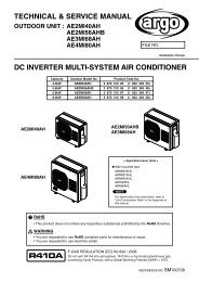
technical data & service manual split system air conditioner - Package
technical data & service manual split system air conditioner - Package
technical data & service manual split system air conditioner - Package
- No tags were found...

Create successful ePaper yourself
Turn your PDF publications into a flip-book with our unique Google optimized e-Paper software.
Table of ContentsPage1. SPECIFICATIONS 41-1 Unit specifications 41-2 Major Component specifications 71-3 Other Component specifications 102. DIMENSIONAL DATA 113. PERFORMANCE DATA 133-1 Air Throw Distance Chart 134. ELECTRICAL DATA 164-1 Electric Wiring Diagrams 164-2 Wiring System Diagrams 175. FUNCTION 185-1 Cool Mode Operation 185-2 Heat Mode Operation 195-3 Auto (cool/heat) Mode Operation 205-4 Dry Mode Operation 215-5 Fan Mode Operation 215-6 Auto Fan Speed 215-7 Forced-Made 225-8 Protection Operations in Cool and Dry Modes 225-9 Protection Operation in Heat Mode 235-10 I Feel Function 255-11 Night Function 255-12 Diagnostic 265-13 Jumpers Configuration 275-14 Contacts for Building Automation 285-15 Maintenance 296. TROUBLESHOOTING 306-1 Check before and after troubleshooting 306-2 Circuit Breaker Trips or Fuse Blows 306-3 Circuit Breaker in several minutes after turning <strong>air</strong> <strong>conditioner</strong> on 306-4 Unit and Compressor do not run 316-5 Some parts of the Air Conditioner do not operate 326-6 Air Conditioner operates, but abnormalities aer observed 336-7 Poor Cooling or Heating 356-8 Excessive Cooling or Hating 366-9 If a Sensor is defective 367. CHECKING ELETRICAL COMPONENTS 377-1 Measurement of Insulation Resistance 377-2 Checking Continuity of Fuse on PCB Ass'y 383
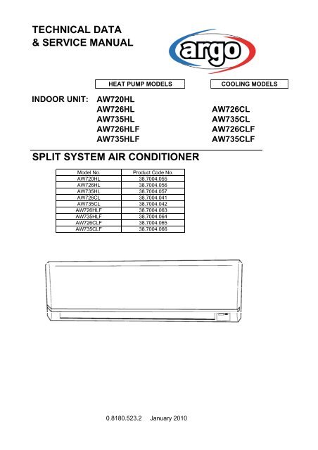
1. SPECIFICATIONS1-1 Unit SpecificationsAW720HLPower sourceVoltage ratingPerformanceCapacityAir circulation (High)m³/h220 - 240 V ~ 50 Hz230 V - 50 HzCoolingHeatingSee catalogue with the requested matching430FeaturesControls/Temperature controlsControl unitTimerFan speedAirflow directionHorizontalVerticalAir FilterPower noise level High/Med./Low dB-ARefrigerant tubing connectionsRefrigerant Narrow tube mm(in.)tube diameter Wide tube mm(in.)RefrigerantAir clean filterMicroprocessor/ I.C. thermostatWireless remote control unitON/OFF 24 hours3 and AutoManualAutoWashable, Anti-Mold48/46/43Flare type6.35 (1/4)9.52 (3/8)R410AOptionalDimensions & WeightUnit dimensions Height mm270Widthmm805Depthmm218<strong>Package</strong> dimensions Height mm273Widthmm855Depthmm322Weight Net kg8.0Shippingkg10.0Shipping volume m 30.075DATA SUBJECT TO CHANGE WITHOUT NOTICE4
AW726HL AW726CL AW726HLF AW726CLFPower sourceVoltage ratingPerformanceCapacityAir circulation (High)m³/h220 - 240 V ~ 50 Hz230 V - 50 HzCoolingHeatingSee catalogue with the requested matching450FeaturesControls/Temperature controlsControl unitTimerFan speedAirflow directionHorizontalVerticalAir FilterPower noise level High/Med./Low dB-ARefrigerant tubing connectionsRefrigerant Narrow tube mm(in.)tube diameter Wide tube mm(in.)RefrigerantAir clean filterMicroprocessor/ I.C. thermostatWireless remote control unitON/OFF 24 hours3 and AutoManualAutoWashable, Anti-Mold50/45/41Flare type6.35 (1/4)9.52 (3/8)R410AOptionalDimensions & WeightUnit dimensions Height mm270Widthmm805Depthmm218<strong>Package</strong> dimensions Height mm273Widthmm855Depthmm322Weight Net kg8.0Shippingkg10.0Shipping volume m 30.075DATA SUBJECT TO CHANGE WITHOUT NOTICE5
AW735HL AW735CL AW735HLF AW735CLFPower sourceVoltage ratingPerformanceCapacityAir circulation (High)m³/h220 - 240 V ~ 50 Hz230 V - 50 HzCoolingHeatingSee catalogue with the requested matching470FeaturesControls/Temperature controlsControl unitTimerFan speedAirflow directionHorizontalVerticalAir FilterPower noise level High/Med./Low dB-ARefrigerant tubing connectionsRefrigerant Narrow tube mm(in.)tube diameter Wide tube mm(in.)RefrigerantAir clean filterMicroprocessor/ I.C. thermostatWireless remote control unitON/OFF 24 hours3 and AutoManualAutoWashable, Anti-Mold50/45/41Flare type6.35 (1/4)12.7 (1/2)R410AOptionalDimensions & WeightUnit dimensions Height mm270Widthmm805Depthmm218<strong>Package</strong> dimensions Height mm273Widthmm855Depthmm322Weight Net kg8.0Shippingkg10.0Shipping volume m 30.075DATA SUBJECT TO CHANGE WITHOUT NOTICE6
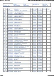
1-2 Major Component SpecificationsAW720HLController PCBPart No.ControlsControl circuit fuseJumper setting JP1..JP5Remote Control UnitFan & Fan MotorTypeQ'ty ……. Dia. and lenghtFan motor model…Q'tyNo. Of poles…rpm (230 V, Hi)Nominal outputCoil resistance (Ambient temp. 20 °C )mmWΩSafety devicesTypeOperating temp. Open °CCloseRun capacitor µFVACSAC ON-OFF IDUMicroprocessor250 V - 3,15 A2,54mm-5pcsSAC W-REMCross - flow1…. Ø 95 / L 617KFV4Q-11H5P-S…14…116010BRN-WHT: 561,8VLT-WHT: 197,4VLT-ORG: 63,4YEL-ORG: 155,7YEL-PNK: 115,9internal fuse145 ± 5-0,6440Flap MotorTypeModelRatingCoil resistance (Ambient temp. 25 °C )Heat Exch. CoilCoilRowsFin pitchFace areaΩmmStepping motorMP24GA1DC 12 V380 ± 7%Aluminium plate fin / Copper tube21,40,130DATA SUBJECT TO CHANGE WITHOUT NOTICE7
AW726HL AW726CL AW726HLF AW726CLFController PCBPart No.ControlsControl circuit fuseJumper setting JP1..JP5Remote Control UnitFan & Fan MotorTypeQ'ty ……. Dia. and lenghtFan motor model…Q'tyNo. Of poles…rpm (230 V, Hi)Nominal outputCoil resistance (Ambient temp. 20 °C )mmWΩSafety devicesTypeOperating temp. Open °CCloseRun capacitor µFVACSAC ON-OFF IDUMicroprocessor250 V - 3,15 A2,54mm-5pcsSAC W-REMCross - flow1…. Ø 95 / L 617KFV4Q-11H5P-S…14…116010BRN-WHT: 561,8VLT-WHT: 197,4VLT-ORG: 63,4YEL-ORG: 155,7YEL-PNK: 115,9internal fuse145 ± 5-1440Flap MotorTypeModelRatingCoil resistance (Ambient temp. 25 °C )Heat Exch. CoilCoilRowsFin pitchFace areaΩmmStepping motorMP24GA1DC 12 V380 ± 7%Aluminium plate fin / Copper tube21,40,130DATA SUBJECT TO CHANGE WITHOUT NOTICE8
AW735HL AW735CL AW735HLF AW735CLFController PCBPart No.ControlsControl circuit fuseJumper setting JP1..JP5Remote Control UnitFan & Fan MotorTypeQ'ty ……. Dia. and lenghtFan motor model…Q'tyNo. Of poles…rpm (230 V, Hi)Nominal outputCoil resistance (Ambient temp. 20 °C )mmWΩSafety devicesTypeOperating temp. Open °CCloseRun capacitor µFVACSAC ON-OFF IDUMicroprocessor250 V - 3,15 A2,54mm-5pcsSAC W-REMCross - flow1…. Ø 95 / L 617KFV4Q-11H5P-S…14…125010BRN-WHT: 561,8VLT-WHT: 197,4VLT-ORG: 63,4YEL-ORG: 155,7YEL-PNK: 115,9internal fuse145 ± 5-1440Flap MotorTypeModelRatingCoil resistance (Ambient temp. 25 °C )Heat Exch. CoilCoilRowsFin pitchFace areaΩmmStepping motorMP24GA1DC 12 V380 ± 7%Aluminium plate fin / Copper tube21,40,13DATA SUBJECT TO CHANGE WITHOUT NOTICE9
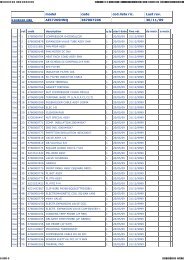
1-3 Other Component SpecificationsTrasformer (TR)RatingCoil resistanceThermal cut-off temp.PrimarySecondaryCapacityΩ (at 25°C)A040C5026AAAC 230 V, 50 Hz13 V - 5VAPrimary: -Secondary: -120°CThermistor ( Coil sensor )ResistanceThermistor ( Room sensor )ResistancekΩkΩNTC-THERMISTOR10 at 25 °CNTC-THERMISTOR10 at 25 °C10
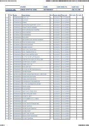
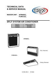
2. DIMENSIONAL DATAAW720HL AW726HL AW735HL AW726CL AW735CL12,7 (1/2") AW735AW720-72611
AW726HLF AW735HLF AW726CLF AW735CLF
3. PERFORMANCE DATA3-1 Air Throw Distance ChartAW720HLCoolingRoom <strong>air</strong> temp. : 27°CFan speed : HighHorizontal distance (m)0 1 2 3 4 5 6 7 8 90Axis <strong>air</strong> verocity (m/s)Vertical distance (m)1234: Flap angle 0° , : Axis <strong>air</strong> velocity 0°: Flap angle 30°, : Axis <strong>air</strong> velocity 30°HeatingRoom <strong>air</strong> temp. : 20°CFan speed : HighHorizontal distance (m)0 1 2 3 4 5 6 7 8 90Axis <strong>air</strong> verocity (m/s)Vertical distance (m)1234: Flap angle 45° , : Axis <strong>air</strong> velocity 45°: Flap angle 60° , : Axis <strong>air</strong> velocity 60°13
AW726HL AW726CL AW726HLF AW726CLFCoolingRoom <strong>air</strong> temp. : 27°CFan speed : HighHorizontal distance (m)0 1 2 3 4 5 6 7 8 90Axis <strong>air</strong> verocity (m/s)Vertical distance (m)1234: Flap angle 0° , : Axis <strong>air</strong> velocity 0°: Flap angle 30°, : Axis <strong>air</strong> velocity 30°HeatingRoom <strong>air</strong> temp. : 20°CFan speed : HighHorizontal distance (m)0 1 2 3 4 5 6 7 8 90Axis <strong>air</strong> verocity (m/s)Vertical distance (m)1234: Flap angle 45° , : Axis <strong>air</strong> velocity 45°: Flap angle 60° , : Axis <strong>air</strong> velocity 60°14
AW735HL AW735CL AW735HLF AW735CLFCoolingRoom <strong>air</strong> temp. : 27°CFan speed : HighHorizontal distance (m)0 1 2 3 4 5 6 7 8 90Axis <strong>air</strong> verocity (m/s)Vertical distance (m)1234: Flap angle 0° , : Axis <strong>air</strong> velocity 0°: Flap angle 30°, : Axis <strong>air</strong> velocity 30°HeatingRoom <strong>air</strong> temp. : 20°CFan speed : HighHorizontal distance (m)0 1 2 3 4 5 6 7 8 90Axis <strong>air</strong> verocity (m/s)Vertical distance (m)1234: Flap angle 45° , : Axis <strong>air</strong> velocity 45°: Flap angle 60° , : Axis <strong>air</strong> velocity 60°15
4. ELECTRICAL DATA4-1 Electric Wiring DiagramsHEAT PUMP MODELSCOOLING MODELS16
4-2 Wiring System DiagramHEAT PUMP MODELSCOOLING MODELS17
5.FUNCTION5-1 Cool Mode OperationIn Cooling Mode, the operation of the compressor (CM), Outdoor Fan (FMO) and Indoor Fan (FMI) aredetermined by the difference between the room <strong>air</strong> temperature (RAT) and the set point temperature (SPT)as shown in the graph.NOTES1. In this graph, the FMI is operating with the “Auto Fan Speed” setting. If the user has selected the Low,Medium or High fan speed, the FMI will run constantly at that speed only.2. In addition to the temperature difference of above, the operations of the main components (CM, FMO,FMI) is also controlled by protection delays. That is: - the minimum off time of compressor is 3 minutes. -- the minimum off time of compressor is 3 minutes. -- the indoor fan can change speed only after it has operated at the same speed for 30 sec if in AUTOand 1 sec for the other settings (High, Med, Low).18
5-2 Heat Mode OperationHEAT PUMP MODELSThe Heating mode operation is similar to the Cooling mode operation. The CM, FMO and FMI are mainlycontrolled by the value of (RAT – SPT). In the graph above, the FMI is operating in AUTO speed mode.Therefore, the FMI speed changes automatically according to the (RT - SPT).NOTES1. After the CM has stopped, the FMI runs for 30s in order to purge heat from the indoor coil.2. The FMI will not be turned on until the indoor coil temperature is warm enough to prevent the supply ofcool <strong>air</strong> (see COLD DRAFT PREVENTION feature for details).The indoor fan can change speed only after it has operated at the same speed for 30 sec if in AUTO and1 sec for the other settings (High, Med, Low).19
5-3 Auto (cool/heat) Mode OperationHEAT PUMP MODELSIn Auto Mode, the unit switches automatically between the Auto Cooling and Auto Heating in order tomaintain the room temperature (RAT) at the prescribed set point (SPT).The switching between the two modes is according to the above graph.Refer to the sections 5.1 COOLING MODE and 5.2 HEATING MODE for <strong>system</strong> operation details.20
5-4 Dry Mode OperationDry operation remove moisture from indoor <strong>air</strong> running, in cooling mode, at a low level without reducing theambient temperature. This is done cycling ON and OFF indoor and outdoor units according to below.ROOMTEMPDRY LEVEL≥ SPT+2°C LEVEL 0 Operation according to COOLING modeCM on< SPT+2°C LEVEL 1 FMO on≥ SPT-1°CFMI switches between L and LL (30 seconds)RV offCM switches 9 minutes off and 3 minutes on< SPT-1°C LEVEL 2 FMO switches 9 minutes off and 3 minutes ON≥ 15°CFMI switches off and L during CM operationRV offCM off< 15°C DRY OFF ZONE FMO offFMI offRV offSPT = Set Point Temperature5-5 Fan Mode OperationWith this mode, the indoor fan is turned on while CM, FMO and RV stay off all the time. The user can selectbetween 3 speeds: HIGH, MEDIUM and LOW.5-6 Auto Fan speedWith this option selected, the indoor fan speed changes automatically according to the difference betweenthe detected <strong>air</strong> temperature (RAT sensor) and the set point (SPT):COOLING MODE2 ≤ (RAT – SPT): HIGH speed1 ≤ (RAT – SPT) < 2: MEDIUM speed(RAT – SPT) < 1:LOW speedHEATING MODE2 ≤ (SPT - RAT): HIGH speed(SPT - RAT) < 2:MEDIUM speedNOTESPT = Set Point Temperature21
5-7 Forced ModeIn this mode the <strong>system</strong> operates (COOLING or HEATING mode – fixed settings) or is switched off bymeans of the MODE button of the indoor unit control board. The operation modes can be selectedpressing the button in a cyclic way (OFF COOL HEAT OFF…). The settings are:COOLING modeSET POINT temperature = 25°CFAN SPEED = HIGHHEATING modeSET POINT temperature = 21°CFAN SPEED = HIGH5-8 Protection operations in Cool and Dry ModeThis protection prevents ice formation on the indoor coil heat exchanger. The protection is activated bythe indoor coil temperature (ICT sensor) and only after 6 minutes of compressor operation. Thisprotection acts in 2 levels:LEVEL 1INDOOR FAN SPEED: ANY (as selected from remote controller)COMPRESSOR: ONOUTDOOR FAN: cycling (30 seconds ON 30 seconds OFF).LEVEL 2INDOOR FAN SPEED: ANY (as selected from remote controller)COMPRESSOR: OFF for at least 6 minutes and until ICT ≥ 8°COUTDOOR FAN: OFF for at least 6 minutes and until ICT ≥ 8°CThe <strong>system</strong> exit this protection routine when ICT temperature rises above 8°C.22
5-9 Protection operations in Heat ModeHEAT PUMP MODELS5-9.1 Cold draftThis feature prevents the supply of cold <strong>air</strong> forcing the indoor fan to a speed which cannot be changedby the user. As soon as the protection mode is exited speed can be changed <strong>manual</strong>ly through theremote controller. The protection acts in the following5-9.2 DefrostThe defrost process is controlled by a detection algorithm designed in order to mantain optimalutilization of the heat pump capacity especially during negative outdoor temperature conditions.During DEFROST OPERATION the main components operates according to the following chart:30 seconds 30 seconds6 seconds 6 seconds23
5-9.3 OverheatThis feature prevents the build up of high pressure in the indoor heat exchanger during heatingoperationABCAW726CL AW735CLAW720HL AW726HL AW735HLA (°C) 59 60 62B (°C) 53 55 57C (°C) 45 46 4824
5-10 I FEEL FunctionAs standard configuration the <strong>air</strong> <strong>conditioner</strong> operates detecting the room temperature through the sensorequipped in the wireless remote controller (icon I FEEL shown on the display). This feature provides apersonalised environment since the temperature can be detected where the remote controller is located.It is possible to de-activate this option pressing the I FEEL button on the remote controller.In this case the I FEEL icon is no longer displayed and room temperature is detected through the sensorincluded in the indoor unit.5-11 NIGHT FunctionWhen this function is active, room temperature changes automatically to compensate for body temperaturevariations while sleeping. After 10 hours of operation <strong>system</strong> switches automatically to OFF state.This mode of operation is available both in COOLING and HEATING mode.25
5-12 DiagnosticWith this feature is possible to have a visual signal that a trouble is occurring.This mode is always active and the signalling is made through the display board LEDS .In case of no troubles the LEDS status follows its normal function.NOTES• The troubles are showed according a priority list that is in case of more than onetrouble present, is always showed, at first, the one with the highest priority (1 2 3 etc).• Sensor damaged means a situation where sensor is short-circuited or opened.• In case of damaged sensors, the <strong>system</strong> (CM, FMO, FMI etc), if in OFF state, does not start.PriorityTROUBLELEDS statusLD1(stby) LD2(opr) LD3(timer)2 RAT damaged F O O3 ICT damaged F F O4 WRONG MODE F F FSELECTEDEffectsSystem does not operateSystem does not operateO = LED off• = LED onF = LED blinkingWARNING: Priority 4 only forCOOLING MODELS26
5-13 JUMPERS CONFIGURATIONJumpers are located on the indoor PCB near the MODE button.HEAT PUMP MODELSCOOLING MODELSUnit is shipped with jumpers set according to the following table:JUMPERJP1JP2JP3JP4JP5STATUSHEAT PUMP MODELSopenopenopenclosedclosedCOOLING MODELSopenclosedopenclosedclosed27
5-14 CONTACTS FOR BUILDING AUTOMATION5-14.1 INPUT CONTACT (J4 - green)The status of this input affects <strong>system</strong> operation according to the following:Contact OPEN : <strong>system</strong> does not operate (always OFF) – inputs from wireless remote controller are not processedContact CLOSED: <strong>system</strong> operates in the normal way according to the inputs coming from wireless remote controller5-14.2 OUTPUT CONTACT (J12)This connector is directly tied to the contact (normally open) of a power relay which activates every time the following alarmcondition occur:• RAT damaged• ICT damagedIn this case when alarm happens, on poles 1 and 3 of J12 connector, 220 VAC-50Hz are available.Max electrical load: 1A- 240VAC28
5-15 MAINTENANCEChanging the Address of the Air ConditionerIn case of more than one <strong>air</strong> <strong>conditioner</strong> operating in the same room, it may be necessary to assign an address to eachunit in order to avoid operation conflicts. Address is set acting on the dip-switches located on the indoor PCB and on theremote controller. The PCB settings must match the corresponding ones on the wireless remote controller.How to change address of the <strong>air</strong> <strong>conditioner</strong>Dip switch is located on the indoor PCB near the buzzer.Set the PCB to the address desideredUNIT SETTINGSADDRESS SW1 SW21 off off2 off on3 on off4 on onAs default switches SW1 and SW2 are in off status (PCB factory state).How to change address on Remote Control UnitDip switch is located on the battery compartment.1) Pull out the door and remove the batteries.2) Set the switch SW1 and SW2 according to the indoor PCB settings(do not act on SW3 and SW4)3) Insert the batteries and pull on the doorAs default switches SW1 and SW2 are in off status (remote controller factory state).29
6)TROUBLESHOOTING6-1 CHECK BEFORE AND AFTER «TROUBLESHOOTING»(A) Check power supply wiring.• Check the power supply wires are correctly connected.(B) Check power supply.• Check that voltage is in specified range (±10% of the rating).• Check that power is being supplied.• WARNING: If the following troubleshooting must be done with power supplied,be careful not to touch any uninsulated live part that can cause eletric shock6-2 CIRCUIT BREAKER TRIPS OR FUSE BLOWS.• When circuit breaker is set to ON, it trips in a few moments. Resetting is not possible.• Measure insulation resistance. There is a possibility of ground fault.If resistance value is 1 Mohm or less, insulation is defective.6-3 CIRCUIT BREAKER TRIPS IN SEVERAL MINUTESAFTER TURNING AIR CONDITIONER ON.1 • There is the possibility of short circuit.30
2 • The unit does not run.6-4 UNIT AND COMPRESSOR DO NOT RUN.The unit does not run when <strong>air</strong> <strong>conditioner</strong> is in the follwing conditions:• When the room temperature is below the setting temperature.• During the protection modes.31
6-5 SOME PARTS OF THE AIR CONDITIONER DO NOT OPERATE.32
6-6 AIR CONDITIONER OPERATES, BUT ABNORMALITIES AREOBSERVED.33
6-7 POOR COOLING OR HEATING.35
6-8 EXCESSIVE COOLING OR HEATING.6-9 A SENSOR IS DEFECTIVE.36
7 CHECKING ELECTRICAL COMPONENTS7-1 Measurement of Insulation ResistanceThe insulation is in good condition if the resistance exceeds 1 MOhma) Power Supply WiresClamp the earthed wire of the power supply wireswith the lead clip of the insulation resistance testerand measure the resistance by placing a probe oneither of the power wires (fig.1).Then measure the resistance between the earthedwire and the other power wires (fig.1).b) UnitClamp an alluminium plate fin or copper tube withthe lead clip of the insulation resistance tester andmeasure the resistance by placing a probe on N terminal,and then on Lterminal the terminal plate (fig.2)c) Measurement of Insulation Resistancefor Electrical PartsDisconnect the lead wires of the disired electricpart from terminal plate, PCB assy, capacitor, etc.Similary disconnect the connector. Then measurethe insulation resistance (fig.1 to 4).Refer to electric wiring diagram.NOTEIf the probe cannot enter the poles because the hole is too narrowthen use a probe with a thinner pin.37
7-2 Checking Continuity of fuse on PCB assyRemove PCB assy from electrical component box (fig.5)Then pull out the fuse from PCB assyCheck continuity of fuse by the multimeter (fig.6)7-3 Checking Motor CapacitorRemove the lead wires from the capacitor terminals,and then place a probe on the capacitor terminalsas shown in fig.7.Observe the deflection of the pointer, setting the resistancemeasuring range of the multimeter to the maximum value.The capacitor is "good" if the pointer bounces to a greatextent and the gradually returns to its original position.The range of deflection and deflection time deffer accordingto capacity of the capacitor.38
Via Varese, 90 - 21013 Gallarate - Va - ItalyTel. +39 0331 755111 - Fax +39 0331 776240www.argoclima.com,